JT850人体感应芯片规格书
850nm-1W芯片规格书
电话:0311-83933091
传真:0311-83933092-802
中国电子科技集团公司第十三研究所
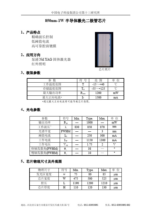
850nm-1W 半导体激光二极管芯片
1、产品特点 精确波长控制 低阈值电流 高可靠腔面镀膜
2、应用方向 泵浦 Nd:YAG 固体激光器 红外照明
3、极限参数
芯片照片
参数
符号 范围
工作温度范围
T
-15~+40
存储温度范围
Tst
-55~+125
最大输出功率
Pmax
1200
Type. 80 500 1200 120
Max. 85 525 1210 130
单位 μm μm μm μm
地址:河北省石家庄市鹿泉开发区昌盛大街 21 号
电话:0311-83933091
传真:0311-83933092-802
中国电子科技集团公司第十三研究所
芯片外形结构示意图(单位:μm)
6、典型测试曲线
最大正向电流*
IF
1500
*超过最大正向电流将可能导致芯片烧毁。
单位 ℃ ℃ mW mA
4、光电参数
参数 输出功率 工作波长** 光谱半宽 阈值电流 工作电流 工作电压 快轴发散角(FWHM) 慢轴发散角(FWHM)
符号 Pop λ FWHM Ith Iop Vop θ⊥ θ∥
Min. — 830 — — — — — —
7、使用注意事项和说明 (1)对芯片的任何机械损伤及沾污可能造成芯片性能下降甚至 失效。 (2)工作波长与封装热阻、环境温度以及注入电流有关。 (3)激光对人眼可能造成伤害,测试及应用本产品请参阅相关 安全标准和法规。 (4)本规格书版本 2013-7,如有更改不另行通知。
DLT8T10 十通道电容式触摸感应控制芯片规格书V1.5
规格说明书DLT8T10 十通道电容式触摸感应控制芯片触摸行业最强资源集成:内置3路PWM版本V1.5目录1. 概述 (3)2. 特性简介 (3)3. 管脚描述 (4)4. 封装(SOP16) (4)5. 绝对最大值 (6)6. 参考应用电路 (6)6.1: BCD码(二进制编码)输出方式 (7)6.2: 点对点输出方式 (7)6.3: ADC电压输出方式 (8)6.4: 频率输出方式 (9)6.5: IIC输出方式 (10)1. 概述DLT8T10是深圳市杰力科创电子有限公司优势产品。
本产品的特点和优势:◆本产品为电容式的触摸感应专用IC◆本产品最多可做10个触摸按键◆可在有介质(如玻璃、亚克力、塑料、陶瓷等)隔离保护的情况下实现触摸功能,安全性高◆也可直接触摸金属等导电部件◆应用电路简单,外围器件少,加工方便,成本低◆本产品经过多年类型客户的检验,稳定性和抗干扰能力等各方面表现优秀,目前已广泛使用于:消费电子、数码产品、安防产品、便携式产品、LED灯具控制、智能开关,智能控制面板等电子产品2. 特性简介●典型工作电压:2.4V~5.5V●工作频率:内置4MHz(RC)●内置上电复位(POR)●内置低电压复位(LVR)●内置稳压电路(LDO)3. 管脚描述表1 管脚描述4. 封装(SOP16)图一DLT8T10-SOP16脚位图图2 DLT8T10-SOP16封装图5. 绝对最大值表2 绝对最大值6. 参考应用电路(注意:凡是没有使用的触摸端口,接地即可)本芯片专门为功能复杂、体积小的应用方案而设计,可以设计的方案无数,以适应客户的各种特定要求,以下提供部分电路供参考,方便客户选型。
其他具体方案,请咨询杰力科创公司业务人员。
方式一:BCD码(二进制编码)输出方式方式二:点对点输出方式方式三:ADC(电压输出)输出方式方式四:频率(不同按键输出不同的频率)输出方式方式五:IIC输出方式方式六:LED灯控方案,例如:1路分档调光,1路无极调光,1路滑动调光、2路分档调光、2路无极调光调色温、2路滑动调光调色温、3路彩灯调光、恒压调光、恒流调光……方式六:其他定制方案6.1: BCD码(二进制编码)输出方式(一个触摸通道对应一个触摸感应PAD,同时对应一个BCD编码信息)说明:此方案适用于:可以根据需要灵活变动按键定义,对I/O口的资源有相当的限制。
人体红外感应芯片 SW02A V3
6/7
Version3.0
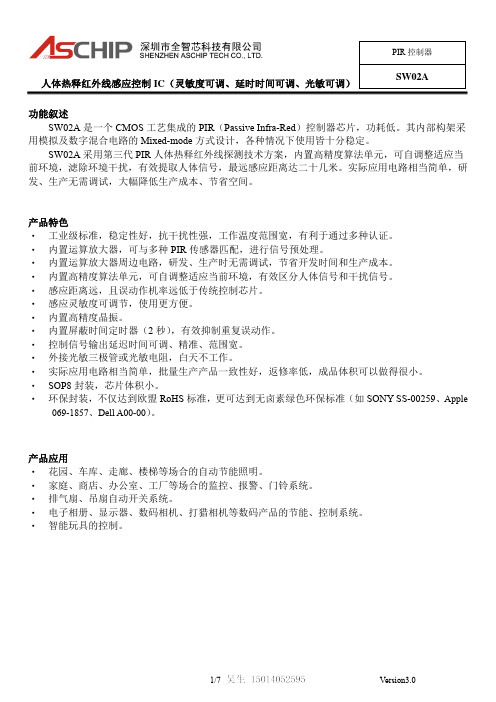
人体热释红外线感应控制 IC(灵敏度可调、延时时间可调、光敏可调)
PIR 控制器
SW02A
电路设计和调试注意事项
1、 PIR SENSER 到 SW02A 的连接线要越短越好。双面板或者多层板上,该连接线下方尽量不要走线,尤其是不能 有大电流的走线。
069-1857、Dell A00-00)。
产品应用 ‧ 花园、车库、走廊、楼梯等场合的自动节能照明。 ‧ 家庭、商店、办公室、工厂等场合的监控、报警、门铃系统。 ‧ 排气扇、吊扇自动开关系统。 ‧ 电子相册、显示器、数码相机、打猎相机等数码产品的节能、控制系统。 ‧ 智能玩具的控制。
1/7
Version3.0
R4 取值(Ω) 不接(断开)
2M 1M 910K 820K 750K 680K 560K 470K 390K 300K 200K 100K 0(短路)
延时时间(秒)
1 1 5 10 15 20 30 45 60 90 120 180 300 480
注: 以上均是 VDD=3.3V 时的取值。改变电压值, 则电阻和延时时间的对应关系也会有所变化。
2、 人体感应部分的电路最好是单独做一块 PCB 板,以避免干扰。如果做在同一块 PCB 板上,人体感应部分的电路 要单独隔离开,有单独的地,只通过正极、负极和输出三根线连接其它电路。
3、 一定要先装上菲涅尔透镜和成品外壳(传感器的铁壳和引脚不能裸露)才能进行测试,否则感应效果差,风吹误 动作很多。
前环境,滤除环境干扰,有效提取人体信号,最远感应距离达二十几米。实际应用电路相当简单,研 发、生产无需调试,大幅降低生产成本、节省空间。
产品特色 ‧ 工业级标准,稳定性好,抗干扰性强,工作温度范围宽,有利于通过多种认证。 ‧ 内置运算放大器,可与多种 PIR 传感器匹配,进行信号预处理。 ‧ 内置运算放大器周边电路,研发、生产时无需调试,节省开发时间和生产成本。 ‧ 内置高精度算法单元,可自调整适应当前环境,有效区分人体信号和干扰信号。 ‧ 感应距离远,且误动作机率远低于传统控制芯片。 ‧ 感应灵敏度可调节,使用更方便。 ‧ 内置高精度晶振。 ‧ 内置屏蔽时间定时器(2 秒),有效抑制重复误动作。 ‧ 控制信号输出延迟时间可调、精准、范围宽。 ‧ 外接光敏三极管或光敏电阻,白天不工作。 ‧ 实际应用电路相当简单,批量生产产品一致性好,返修率低,成品体积可以做得很小。 ‧ SOP8 封装,芯片体积小。 ‧ 环保封装,不仅达到欧盟 RoHS 标准,更可达到无卤素绿色环保标准(如 SONY SS-00259、Apple
JT人体感应芯片规格书
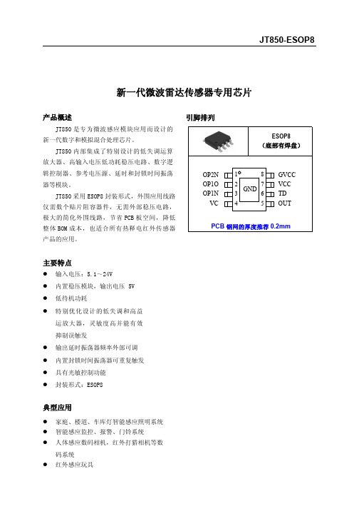
新一代微波雷达传感器专用芯片产品概述JT850是专为微波感应模块应用而设计的新一代数字和模拟混合处理芯片。
JT850内部集成了特别设计的低失调运算放大器、高输入电压低功耗稳压电路、数字逻辑控制器、参考电压源、延时和封锁时间振荡器等模块。
JT850采用ESOP8封装形式,外围应用线路仅需数个贴片阻容器件,无需外部稳压电路,极大的简化外围线路,节省PCB板空间,降低整体BOM成本,也适合所有热释电红外传感器产品的应用。
主要特点●输入电压:5.1~24V●内置稳压模块,输出电压5V●低待机功耗●特别优化设计的低失调和高益运放大器,灵敏度高并能有效抑制误触发●输出延时振荡器频率外部可调●内置封锁时间振荡器可重复触发●具有光敏控制功能●封装形式:ESOP8典型应用●家庭、楼道、车库灯智能感应照明系统●智能感应监控、报警、门铃系统●人体感应数码相机,红外打猎相机等数码系统●红外感应玩具引脚排列123OP2NOP1OOP1N引脚功能序号符号功能描述1OP2N 运放2输入2OP1O 运放1输出3OP1N 运放1输入4VC 禁止触发端,VC>0.2GVCC 时允许触发,VC<0.2GVCC 时禁止触发5OUT 控制信号输出端6TD 延时时间调节端7VCC 电源端8GVCC 稳压输出端9GND接地端(底部焊盘)电路功能框图图 1.电路功能框图OPO OPIV CV CC GV CCGNDOUTTDJT850-ESOP8最大额定值参数说明符号数值范围单位输入电源电压VCC –0.3~26V 其他引脚电压VIO –0.3~6.0V工作温度TOPR -20~70贮存温度TSTG-50~125注意:如果器件运行条件超过上述各项最大额定值,可能对器件造成永久性损坏。
上述参数仅是运行条件的极大值,我们不建议器件在该规范范围外运行。
如果器件长时间工作在绝对最大极限条件下,其稳定性可能会受到影响。
电特性(除特别说明外,V CC =12V ,T A =+25°C )参数说明符号测试条件最小值典型值最大值单位电源电压V CC 5.124V 静态电流I CC 30μA GVCC 输出电压GV CC 5.0V GVCC 输出电流I GVCC GV CC =4.5V30mA 输入失调电压V OS 50mV 输入失调电流I OS 50nA 开环电压增益A VO1R L =1.5M 60dB 共模抑制比CMRR R L =1.5M60dB 内部固定增益G A 40dB 运放输出高电平V YH R L =500K 4.0V 运放输出低电平V YL 0.5V OUT 端输出高电平电流I OH V OH =0.8GV CC 10mA OUT 端输出低电平电流I OL V OL =0.2GV CC10mA 封锁时间T LOCK1.522.5S℃℃典型应用线路图功能描述JT850内置稳压电路,输入电压最高可达24V,输出电压5.0V,输出电流能为30mA,可以为PIR 供电。
PA-850型号压力传感器说明书

PRESSURE TRANSDUCERS WITH AMP.PA-850■FEATURES■MODEL NUMBER DESIGNATIONPA-850 - 102 R - N R2Series namePressure reference Rated pressure rangeG:GaugeV:Gauge (Vacuum)R:CompoundA:Absolute102:0 ~ 100 kPa352:0 ~ 350 kPa103:0 ~ 1000 kPa102:0 ~ − 100 kPa102:− 100 ~ 100 kPa302:− 100 ~ 300 kPa102:0 ~ 100 kPa absFittingR2:R 1/4 with M 5 female screwGF:G 3/8 with flash diaphragmG2:G 1/4 with M 5 female screwSwitch output interfaceN:NPN open collector(Upper limit mode)P:PNP open collector(Upper limit mode)※Please refer to the LIST OF MODEL NUMBERS when placing orders.●High corrosion resistance and drip-proof constructionPressure port attachment made of SUS 316LProven IP-65 grade gauge body (IP-65 in accordance with IEC)●Stand ard prod uct provid es both a switch output(hysteresis adjustable) and an analog output●Absolute pressure type and compound pressure typewhich can control negative to positive pressure with onlya single pressure gauge are all in line●Three standard types of joint are providedR2 : R 1/4 (M 5 female screw)GF : G 3/8 with flash diaphragmG2 : G 1/4 (M 5 female screw)■LIST OF MODEL NUMBERS※Verify the above model numbers when placing orders.PA-850PRESSURE TRANSDUCERS WITH AMP .■STANDARD SPECIFICATIONS※1 An “O” ring provided.(G 3/8 : P18、G 1/4 : P15)● Unless otherwise specified, the specs are defined at an ambient temperature of 25±5 °C and excitation voltage of 12 V DC.PA-850PRESSURE TRANSDUCERS WITH AMP .■ENVIRONMENTAL CHARACTERISTICS●Configurations of joint R2 (R1/4) type●Configurations of joint GF (G 3/8) type●Configurations of joint G2 (G 1/4) type■OUTLINE DIMENSIONS Unless otherwise specified, tolerance : ± 0.5 (Unit: mm) PA-850PRESSURE TRANSDUCERS WITH AMP.Extra care should be taken with the diaphragm part. Do not touch the diaphragm directly to avoid damaging the diaphragm.ShieldS.OutputA.Output Power B Common ShieldS.OutputCommon A.Output Power BOFF- pressurepressureON OFF-vacuunON OFFON OFFON PA-850PRESSURE TRANSDUCERS WITH AMP .■INTERNAL ELECTRICAL SCHEMATICS● NPN output● PA-850-102V● PA-850-***G● PA-850-***R● PA-850-***A● PNP output■SWITCH OUTPUT SCHEMATICSTurns on at the set pressure and turns off at the set pressure minus the hysteresis.※Adjustable hysteresis。
音频功放芯片WT8509说明书
WT8509功放芯片说明书V1.00 Note:WAYTRONIC ELECTRONIC CO.,LTD.reserves the right to change this document without prior rmation provided by WAYTRONIC is believed to be accurate and reliable.However,WAYTRONIC makes no warranty for any errors which may appear in this document.Contact WAYTRONIC to obtain the latest version of device specifications before placing your orders.No responsibility is assumed by WAYTRONIC for any infringement of patent or other rights of third parties which may result from its use.In addition,WAYTRONIC products are not authorized for use as critical components inWT8509输出功率D 类模式输出功率-AB 类模式QDD=8.5V ,THD+N=10%VDD=8.5V,THD+N=10%RL=8Ω 4.20W RL=8Ω 4.00V RL=4Ω8.50W RL=4Ω8.00WVDD=5.0V,THD+N=1%VDD=5.0V,THD+N=10%RL=8Ω 1.5W RL=8Ω 1.30W RL=4Ω 2.65W RL=4Ω 3.00W ・工作电压范围2.5-9.2V・优异的”噗呲-咔嗒"(pop-noise)张音抑制能力・无需滤波的class-D 结构・D 类模式高达90%的效率・高的电源抑制比(PSRR):在217Hz 下为-80dB ・快速的启动时间(200ms)・低静态电流(3mA)・低关断电流(<0.1uA)・过流保护,短路保护和过热保护・符合Rohs 标准的无铅封装应用:・多媒体音箱・扩音器序号符号描述SD 掉电控制管脚,低电平芯片关闭,高电平芯片开启ABD AB 类/D 类切换选择,L 选择AB 类模式,H 选择D 类模式IN+音频输入正端IN-音频输入负端VDD 电源V0+正向音频输出VO-反向音频输出GND地WT8509是一款高效率,超低EMI ,AB 类D 类模式可切换的8.0W 单声道音频放大器。
高精度数字电容传感芯片 MDC04 产品手册(V3.4)说明书
高精度数字电容传感芯片MDC04产品手册(V3.4)©敏源传感科技有限公司2021/07目录1.产品简介 (1)1.1概述与应用 (1)1.2特性 (1)1.3功能框图 (1)2.引脚配置及功能 (2)2.1引脚列表 (2)2.2应用电路 (3)2.2.1单总线接口方式 (3)2.2.2I²C接口方式 (4)3.技术规格 (4)3.1电气特性 (4)3.1.1.绝对最大额定值 (5)3.1.2.非易失性存储器特性 (5)3.2.单总线接口时序 (5)3.3.I2C接口时序 (6)4.电路描述 (7)4.1.电容转换 (7)4.1.1.偏置电容和测量范围配置以及通道选择 (8)4.1.2.偏置电容设置寄存器Cos (8)4.1.3.系统配置寄存器Cfg (9)4.1.4.系统状态寄存器 (9)4.2.温度转换 (10)5.循环冗余校验(CRC)计算 (10)6.单总线通信接口 (11)6.1.单总线寄存器访问 (11)6.2.复位 (12)6.3.ROM指令 (14)6.4.功能指令 (15)6.5.MDC04运行示例 (17)6.5.1.示例1 (17)6.5.2.示例2 (18)7.I²C通信接口 (19)7.1.I2C寄存器访问 (19)7.2.读写指令 (19)7.3.操作与通信 (20)7.3.1.上电及通信起始 (20)7.3.2.开始测量 (20)7.3.3.单字节读和写指令 (21)7.3.4.设定配置寄存器指令 (22)7.3.5.读取状态寄存器和配置寄存器指令 (22)7.3.6.复位状态寄存器指令 (22)7.3.7.偏置电容、反馈电容和通道选择寄存器访问 (23)7.3.8.单次测量模式指令 (23)7.3.9.连续测量模式指令 (24)7.3.10.单次和连续测量模式下读取数据 (24)7.3.11.停止连续测量模式指令 (25)7.3.12.复位 (25)7.3.13.寄存器保存和恢复指令 (26)7.3.14.自动配置偏置电容指令 (26)8.封装 (28)附录一:不同电容测量范围的配置 (29)1.产品简介1.1 概述与应用电容型传感芯片MDC04是高集成度的数字模拟混合信号传感集成电路,芯片直接与被测物附近的差分电容极板相连,利用不同物质介电常数的区别,通过放大、数字转换、补偿计算电容的微小变化来实现物质成分的传感。
SC01B单键电容触摸感应芯片规格书说明书
2021.8SC01B单键电容触摸感应芯片(智能马桶人体感应、液位检测)1.概览1.1概述SC01B 是单键电容触摸感应器,它可以通过任何非导电介质(如玻璃和塑料)来感应电容变化。
通过设置,SC01B 可以应用于普通触摸按键开关、智能马桶人体感应、水位检测。
1.2特性◇普通按键应用。
◇智能马桶人体感应应用。
◇水位检测应用。
◇保持自动校正,无需外部干预◇按键输出经过完全消抖处理◇并行一对一输出◇2.5V ~6.0V 工作电压◇符合RoHS 指令的环保SOP8封装1.3应用◇替代机械开关,门禁按键,灯控开关◇玩具和互动游戏的人机接口◇密封键盘面板◇金属触摸按键◇马桶着座感应器◇洗地机清水箱液体检测◇各种容器水箱液位检测◇净水器设备液体检测1.4封装SC01B 采用SOP8封装图1-1:封装简图1234V M O C1.5管脚表1-1:管脚汇总管脚顺序名称类型功能1GND Pwr电源地2CMOD I/O接电荷收集电容3CDC I/O接灵敏度电容4CIN1I/O触摸检测端5CIN2I/O触摸检测端6OUT OD感应按键输出7MD I/O模式设置端8VDD Pwr电源管脚类型I CMOS输入I/O CMOS输入/输出OD NMOS开漏输出Pwr电源/地1.6管脚说明VDD,GND电源正负输入端。
CMOD电荷收集电容输入端,接固定值的电容,和灵敏度无关。
CDC接灵敏度电容,电容范围是最小5pf,最大100pf。
根据使用环境选择合适的电容值,数值越小,灵敏度越高。
CIN1感应电容的输入检测端口。
当用于智能马桶人体感应及液位检测应用时,接固定电容作为比较参考电容;当用于普通按键锁存输出应用时,接触摸按键输入。
CIN2感应电容的输入检测端口。
当用于智能马桶人体感应及液位检测应用时,接触摸按键输入;当用于普通按键检测功能时,管脚悬空。
OUT触摸输出端口。
端口内部结构为带上拉电阻的NMOS开漏输出,输出弱高或强低电平,有效电平是强低电平。
四方面浅谈850nm红外发射管基本知识-中国LED网
四方面浅谈850nm红外发射管基本知识2006年6月30日 8:55 来源:中国安防网从2004年开始,红外发射管在安防行业的应用越来越普及,其主要用在红外一体目前,红外一体机的制造集中在珠三角,大约有500家生产企业,其中以台湾、香港等外资企业势力较强,其产品全部外销,而其它绝大多数是中小型私人企业,其产品以内外销结合方式销售,而红外灯的制造企业以京津地区和东北地区为主,大约200家左右,其产品几乎全部内销。
受国家相关政策的影响,安防行业还将有三到五年的高速发展期,将会有更多企业进入此行业。
然而,目前很多企业技术不成熟,设计产品时进入误区,一心追求距离,希望找到距离又远监控范围又广的红外LED,其实这是不明智的,鉴于此,在此给更多的朋友介绍一些发射管的知识,希望对大家有所帮助。
一、发射管晶片目前850nm发射管晶片主要由日本、台湾、韩国、德国、大陆企业提供,而台湾大陆企业的晶片,其外延片主要来自于日本和韩国,功率、光衰最好的是日本制造的,台湾鼎元的外延片来自于日本,其提供的晶片在该行业的口碑也较好。
目前,日本晶片厂除对外提供外延之外,其已开始自己切割,这必将对台湾和大陆的晶片厂造成压力。
二、850nm发射管的封装目前做850nm发射管封装的公司很多,但是其懂得封装的细节,懂得封装细节对发射管影响的公司很少;要封装出品质好的IR发射管,首先要选好材料,主要材料是晶片、银浆、胶水、支架等;晶片的选择决定其功率、光衰,目前用日本和台湾的晶片最好;银浆的选择对其死灯现象影响较大,目前最好的银浆来自日本和英国;胶水决定其耐热性能,目前最好的胶水是台湾原厂的,其应力好,耐高温,封出的IR发射管表面偏雾和略偏黄,有的公司使用的胶水很透明有些偏兰的感觉,这种胶水用于一般的LED还可以,但不适合封装IR发射管,其不耐高温、进行波峰焊(浸焊)易死灯。
三、850发射管的选择一般的一体机设计距离较近,一般适用较大角度的IR发射管,市场上最通用45、60度角,可选择一般晶片,最好还是选择日本和台湾的,市场上用12Pcs、14Pcs、18Pcs、24Pcs发射管的一体机,常用此类产品一般开发距离在5-20米,若开发20米以上的一体机,必需建议使用日本和台湾晶片,如28Pcs、36Pcs、48Pcs、64Pcs等产品,同时需选用较小角度的效果会更好。
SmartLine STT850高性能温度传感器说明书
SmartLineTechnical InformationSTT850 SmartLine Temperature Transmitter Specification34-TT-03-14, September 2017IntroductionPart of the SmartLine® family of products, the SmartLine STT850 is a high-performance temperature transmitter offering high accuracy and stability over a wide range of process and ambient temperatures. The SmartLine family is also fully tested and compliant with Experion ® PKS providing the highest level of compatibility assurance and integration capabilities. SmartLine easily meets the most demanding needs for temperature measurement applications.Best in Class Features:Industry leading performanceo Digital Accuracy up to +/- 0.10 Deg C for RTD oStability up to +/- 0.01% of URL per year for ten years o 125 mSec update time for single input models o250 mSec update time for dual input modelsReliable measuremento Built in Galvanic IsolationoDifferential/Averaging/Redundant/Split Range measurements o Dual Compartment Housing o Sensor Break detectiono Comprehensive on-board diagnostic capabilities o Full compliance to SIL 2/3 requirements. o Available with 15 year warrantyo Supports Namur 107 Extended Diagnostics o Supports Namur 89 Wire breakoDirect entry of Callendar-Van Dusen coefficients R 0, α, δ and β for calibrated RTD sensors (not available on DE units)Figure 1– Smartline STT850 Temperature transmitterLower Cost of Ownershipo Universal input o Dual sensor optiono Multiple local display capabilities o Modular constructiono External zero, span, & configuration capability o Polarity insensitive loop wiringoDigital Output Option (only available with HART)Communications/Output Options:o 4-20 mA dco Honeywell Digitally Enhanced (DE) o HART ® (version 7.0)oFOUNDATION™ Fieldbus compliant to ITK 6.1.2All transmitters are available with the above listed communications protocols.DescriptionThe SmartLine Temperature Transmitter is designed and manufactured to deliver very high performance across varying ambient temperature. The total accuracy of the transmitter including the ambient temperature effect in harsh industrial environments, allows the STT850 to replace virtually any competitive transmitter available today.Unique Indication/Display OptionsThe STT850 modular design accommodates a basic alphanumeric LCD display or a unique advanced graphics LCD display with many unparalleled features.Basic Alphanumeric LCD Display Featureso Modular (may be added or removed in the field)o0, 90,180, & 270 degree position adjustmentso Deg C , F, R and Kelvin measurement unitso 2 Lines 16 Characters (4.13H x 1.83W mm)o Up to 8 display screens with similar formatso Configurable screen rotation timing (3 to 30 sec)o Auto/Manual selection for screen rotationo Displays up to 9 Datapoints - Loop PV, CJTemperature, Sensor 1, Sensor 2, Sensor Delta,RTD 1 Resistance, RTD 2 Resistance,Loop output, Percent Loop.o Out of Range Indicationo PV Status and critical fault indicationAdvanced Graphics LCD Display Featureso Modular (may be added or removed in the field)o0, 90, 180, & 270 degree position adjustmentso Up to eight display screens with 3 formats are possible (Large PV with Bar Graph or PV with Trend Graph)o Configurable screen rotation timing (3 to 30 sec)o Provides instant visibility for diagnosticso Multiple language capability. (EN, GE, FR, IT, SP, RU, TR, CN & JP)Configuration ToolsIntegral Three Button Configuration OptionSuitable for all electrical and environmental requirements, SmartLine offers the ability to configure the transmitter and display via three externally accessible buttons when either display option is selected. Zero or span capabilities are also optionally available via these buttons with or without selection of a display option.Hand Held ConfigurationSmartLine transmitters feature two-way communication and configuration capability between the operator and the transmitter. This is accomplished via Honeywell’s field-rated Multiple Communication Configuration tool.The Honeywell Handheld MC Toolkit is capable of field configuring DE and HART Devices and can also be ordered for use in intrinsically safe environments. All Honeywell transmitters are designed and tested for compliance with the offered communication protocols and are designed to operate with any properly validated hand held configuration device.Personal Computer ConfigurationHoneywell’s SCT 3000 Configuration Toolkit provides an easy way to configure Digitally Enhanced (DE) instruments using a personal computer as the configuration interface.Field Device Manager (FDM) Software and FDM Express are also available for managing HART & Fieldbus device configurations.DiagnosticsSmartLine transmitters all offer digitally accessible diagnostics which aid in providing advanced warning of possible failure events minimizing unplanned shutdowns, providing lower overall operational costsSystem Integrationo SmartLine communications protocols all meet the most current published standards for HART/DE/Fieldbus.o Integration with Honeywell’s Experion PKS offers the following unique advantages.o Transmitter messagingo Maintenance mode indicationo Tamper reporting (HART only)o FDM Plant Area Views with Health summarieso All STT850 units are Experion tested to provide the highest level of compatibility assuranceModular DesignTo help contain maintenance & inventory costs, all STT850 transmitters are modular in design supporting the user’s ability to replace temperature boards, add indicators or change electronic modules without affecting overall performance or approval body certifications. Each temperature board is uniquely characterized to provide in-tolerance performance over a wide range of application variations in temperature and due to the Honeywell advanced interface, electronic modules may be swapped with any electronics module without losing in-tolerance performance characteristicsModular Featureso Replace Temperature/Terminal board/Lightning protection*o Exchange/replace electronics/comms modules*o Add or remove integral indicators*o Add or remove external configuration buttons* Field replaceable in all electrical environments (including IS) except flameproof without violating agency approvals.With no performance effects, Honeywell’s unique modularity results in lower inventory needs and lower overall operating costs.Digital Output OptionAn optional Digital Output (open collector type) is available on HART transmitters which can be used to activate external equipment when preset Alarm Setpoints are reached. The Digital Output can be set to monitor two independent setpoints based upon the analog value of the PV or upon device status.The following Alarm Types are available:· PV High· PV Low· Critical Diagnostic Active· Redundant Input Active**· PV Rate of Change Alarm *· PV Deviation Alarm *Alarms can be configured as latching or non-latching. Alarm Blocking is also available which allows start-up without the alarm energizing until it first reaches the operating region.Alarm Hysteresis is configurable from 0 to 100% of PV range.The Digital Output functionality and status is also available over the HART communications link.* These Alarm Types are available as part of the Advanced Diagnostics option. Rate of Change monitors the rate at which the PV is changing, configurable as either increasing or decreasing. Deviation monitors the PV delta from a separately configurable Setpoint value.** Available only via Communications StatusSee the Wiring Diagramsfor further information.Performance Specifications1,322. Total analog accuracy is the sum of digital accuracy and output D/A Accuracy3. Output D/A Accuracy is applicable to the 4 to 20 mA Signal output4. For TC inputs, CJ accuracy shall be added to digital accuracy to calculate the total digital accuracy5. These input types are not available on DE units6. Custom Callendar-van Dusen not available for Pt25 sensorsDifferential Temperature MeasurementSmartLine Temperature supports differential temperature measurements between any two types of sensors.When the loop current mode is set to "Differential" then the input range is from A to B for sensor 1 & 2 whereA = Sensor 1 Minimum - Sensor 2 MaximumB = Sensor 1 Maximum - Sensor 2 MinimumCallendar - van Dusen Algorithm (CVD)The easy to use Callendar - van Dusen (CVD) algorithm allows the use of calibrated Platinum RTD sensors to increase the overall system accuracy. Simply enable the algorithm and then enter the four CVD coefficients supplied with the calibrated RTD sensor into the transmitter.Digital Accuracy for differential temperature measurementIf both the inputs are similar the digital accuracy equals 1.5 times the worst case accuracy of either sensor type.For mixed input types, the digital accuracy is the sum of sensor 1 and sensor 2 digital accuracies.Performance under Rated Conditions – All Models (continued)Parameter DescriptionEMC Compliance EN 61326-1 and EN 61326-3-1 (SIL)Lightning Protection Option Leakage Current: *****************°CImpulse rating: 8/20 uS 5000 A (>10 strikes) 10000 A (1 strike min.)10/1000 uS 200 A (> 300 strikes)Operating Conditions – All ModelsParameter ReferenceConditionRated Condition Operative Limits Transportation andStorage︒C ︒F ︒C ︒F ︒C ︒F ︒C ︒FAmbient Temperature1STT850 25±1 77±2 -40 to 85 -40 to 185 -40 to 85 -40 to 185 -55 to 120 -67 to 248 Humidity %RH 10 to 55 0 to 100 0 to 100 0 to 100Supply Voltage Load Resistance HART Models: 11.8 to 42.4 Vdc at terminals (IS versions limited to 30 Vdc) 0 to 1,400 ohms (as shown in Figure 2)DE Models: 13.8 to 42.4 Vdc at terminals (IS versions limited to 30 Vdc)0 to 1,300 ohms (as shown in Figure 2)FF Models: 9.0 to 32.0 Vdc at terminals1 LCD Display operating temperature -20︒C to +70︒C . Storage temperature -30︒C to 80︒C.Figure 2 - Supply voltage and loop resistance chart & calculations(not applicable for Fieldbus)Communications Protocols & DiagnosticsHART ProtocolVersion:HART 7Power SupplyVoltage: 11.8 to 42.4Vdc at terminalsLoad: Maximum 1400 ohms See figure 2Minimum Load: 0 ohms. (For handheld communications a minimum load of 250 ohms is required)IEC 61508 Safety Certified SIL 2 and SIL 3Honeywell Digitally Enhanced (DE)DE is a Honeywell proprietary protocol which provides digital communications between Honeywell DE enabled field devices and Hosts.Power SupplyVoltage: 13.8 to 42.4Vdc at terminalsLoad: Maximum 1300 ohms See figure 2Foundation Fieldbus (FF)Power Supply RequirementsVoltage: 9.0 to 32.0 Vdc at terminalsSteady State Current: 17.6 mASoftware Download Current: 27.6 mAP = PermanentI = InstantiableThe AI function block allows the user to configure the alarms to HIGH-HIGH, HIGH, LOW, or LOW-LOW with a variety of priority levels and hysteresis settings.All available function blocks adhere to FOUNDATION Fieldbus standards. PID blocks support ideal & robust PID algorithms with full implementation of Auto-tuning. Link Active SchedulerTransmitters can perform as a backup Link Active Scheduler (LAS) and take over when the host is disconnected. Acting as a LAS, the device ensures scheduled data transfers typically used for the regular, cyclic transfer of control loop data between devices on the Fieldbus.Number of Devices/SegmentEntity IS model: 15 devices/segmentSchedule Entries45 maximum schedule entries50 maximum LinksNumber of VCR’s: 50 maxCompliance Testing: Tested according to ITK 6.1.2Software DownloadUtilizes Class-3 of the Common Software Download procedure as per FF-883 which allows any field devices to receive software upgrades from any host.8 STT850 Smart TemperatureStandard DiagnosticsSTT850 top level diagnostics are reported as eithercritical or non-critical as listed below. All diagnostics arereadable via the DD/DTM tools. All critical diagnosticswill appear on the Basic and Advanced integral displays,non-critical diagnostics will appear on the Advancedintegral display.Critical Diagnostics- Sensor Module Fault- Communications Module Fault- Sensor Communications Fault- Input 1 Fault- Input 2 FaultNon Critical Diagnostics (for Advanced Display only)- Cal 1 Correct- Cal 2 Correct- Sensor Temperature- Sensor 1 Health- Sensor 2 Health- Input 1 Range- Input 2 Range- CJ Range- Input 1- Input 2- Input 1 TB5 (For RTD and Ohm types only)- Input 1 TB6 (for RTD and Ohm types only)- Input TB7 (Input 1 or 2, for RTD and Ohm types only)- Input 1 TB8 (for 4-Wire RTD and Ohm types only)- Input 2 TB8 (for RTD and Ohm types only)- Input 2 TB9 (for RTD and Ohm types only)- Factory Calibration- Loop Supply Voltage (not available on Fieldbus)- Communications Module Temperature- DAC Temperature Compensation (not available onFieldbus)- Sensor Communications- Display Setup (not for Fieldbus)- Excess Delta AlertSTT850 Smart Temperature 9 Approval Certifications:10 STT850 Smart Temperature1.Operating Parameters:4-20 mA/DE/HART (Loop Terminal)Voltage= 11 to 42 V Current= 4-20 mA Normal (3.8 – 23 mA Faults)FF (Loop Terminal)Voltage= 9 to 32 V Current= 25 mA2. Intrinsically Safe Entity ParametersTerminals 1 and 2- LOOP: Ui = 30 Vdc, Ii = 225 mA, Pi = 900 mW, Ci = 4 nF, Li = 0 µH Terminals 5, 6, 7, 8, 9- SENSOR: Ci = 4 nF, Li = 0 µHDIGITAL OUTPUT OPTION:Terminals 1 and 2- LOOP: Ui = 30 Vdc, Ii = 225 mA, Pi = 900 mW, Ci = 4 nF, Li = 0 µH Terminals 4 and 9, DO OPTION: Ui = 30 Vdc, Ii = 40 mA, Pi = 500 mW, Ci = 4 nF, Li = 0 µH Terminals 5, 6,7, 8 - SENSOR: Ci = 4 nF, Li = 0 µHSIL 2/3 Certification IEC 61508 SIL 2 for non-redundant use and SIL 3 for redundant use according to EXIDA and TÜV Nord Sys Tec GmbH & Co. KG under the following standards: IEC61508-1: 2010; IEC 61508-2: 2010; IEC61508-3: 2010.MID Approval Issued by NMi Certin B.V. in accordance with WELMEC guide 8.8, OIML R117.1 Edition 2007(E), and EN 12405-1+A2 Edition 2006. Applicable to Pt100 sensor only.MARINE TYPE APPROVAL Lloyd’s Register Certificate Number: 16/60011Environmental categories ENV1, ENV2, ENV3 and ENV5 as defined in Lloyd’s Register Test Specification No. 1, February 2015Wiring DiagramsDE- Single InputWiring DiagramRTD Thermocouple,mV and OhmConnectionsDE- Dual Input WiringDiagram1Thermocouple andRTD Connections1 Not applicable forsingle input sensorHART/FF – Single Input Wiring Diagram RTD Thermocouple, mV and Ohm ConnectionsHART/FF – Dual Input Wiring DiagramRTD Thermocouple, mV and Ohm ConnectionsHART/FF Dual Input Wiring Diagram Remote C/J and Mixed Sensors ConnectionsDigital Output Connections for mA Load (HART only)Digital Output Connections for PLC Counting Input (HART only)Mounting & Dimensional DrawingsTRANSMITTER ENCLOSURE CAN BE ROTATED A TOTAL OF 90O FROM THE STANDARD MOUNTING POSITION Figure 3 – STT850 with adapter housing - Horizontal Wall MountingFigure 4 – STT850 No-Adapter Horizontal Wall MountingFigure 5 – STT850 Pipe Mount with adapter housing - Horizontal & VerticalFigure 6 - STT850 Pipe Mount, Vertical*Note 1: Figures 5 and 6. The housing adapter may not be present on all transmitter models. If the housing adapter is not present, subtract 24,5mm (0,96 inches) from the dimension specified.Mounting & Dimensional DrawingsReference Dimensions:millimetersinchesFigure 7 – STT850 with adapter housing - DimensionsFigure 8 – STT850 no adapter housing dimensionsModel STT850Smart Temperature TransmitterModel Selection Guide:34-44-16-14 Issue 9The Model Selection Guide is subject to change and is inserted into the specification as guidance only.Prior to specifying or ordering a model check for the latest revision Model Selection Guide which is published at: /en-US/pages/default.aspxModel Selection Guide3 NAMUR Output Limits 3.8 - 20.5mAdc can be configured by the customer or select custom configuration Table VcSTT850 Smart Temperature 21For more informationTo learn more about SmartLine Temperature, visit Or contact your Honeywell Account ManagerProcess Solutions Honeywell1250 W Sam Houston Pkwy S Houston, TX 77042Honeywell Control Systems LtdHoneywell House, Skimped Hill Lane Bracknell, England, RG12 1EB34-TT-03-14 September 20172017 Honeywell International Inc.Shanghai City Centre, 100 Jungi Road Shanghai, China 20061Sales and ServiceFor application assistance, current specifications, pricing, or name of the nearest Authorized Distributor, contact one of the offices below.ASIA PACIFICHoneywell Process Solutions, (TAC) hfs-tac-*********************AustraliaHoneywell LimitedPhone: +(61) 7-3846 1255 FAX: +(61) 7-3840 6481 Toll Free 1300-36-39-36 Toll Free Fax: 1300-36-04-70China – PRC - Shanghai Honeywell China Inc.Phone: (86-21) 5257-4568 Fax: (86-21) 6237-2826SingaporeHoneywell Pte Ltd.Phone: +(65) 6580 3278 Fax: +(65) 6445-3033South KoreaHoneywell Korea Co Ltd Phone: +(822) 799 6114 Fax: +(822) 792 9015EMEAHoneywell Process Solutions, Phone: + 80012026455 or +44 (0)1202645583Email: (Sales)***************************or (TAC)*****************************AMERICA’SHoneywell Process Solutions, Phone: (TAC) 1-800-423-9883 or 215/641-3610(Sales) 1-800-343-0228Email: (Sales)*************************** or (TAC)*****************************Specifications are subject to change without notice.。
- 1、下载文档前请自行甄别文档内容的完整性,平台不提供额外的编辑、内容补充、找答案等附加服务。
- 2、"仅部分预览"的文档,不可在线预览部分如存在完整性等问题,可反馈申请退款(可完整预览的文档不适用该条件!)。
- 3、如文档侵犯您的权益,请联系客服反馈,我们会尽快为您处理(人工客服工作时间:9:00-18:30)。
TOPR
-20~70
℃
贮存温度
TSTG
-50~125
℃
注意:如果器件运行条件超过上述各项最大额定值,可能对器件造成永久性损坏。上述参数仅是运行条件的极大 值,我们不建议器件在该规范范围外运行。如果器件长时间工作在绝对最大极限条件下,其稳定性可能会受到影 响。
电特性(除特别说明外,VCC=12V,TA = + 25°C)
典型应用
家庭、楼道、车库灯智能感应照明系统 智能感应监控、报警、门铃系统 人体感应数码相机,红外打猎相机等数
码系统 红外感应玩具
引脚功能
JT850-ESOP8
序号 1
符号 OP2N
2
OP1O
3
OP1N
4
VC
5
OUT
6
TD
7
VCC
8
GVCC
9
GND
电路功能框图
运放 2 输入
功能描述
运放 1 输出 运放 1 输入 禁止触发端,VC>0.2GVCC 时允许触发,VC<0.2GVCC 时禁止触发 控制信号输出端 延时时间调节端 电源端 稳压输出端 接地端(底部焊盘)
OUTPUT
功能描述
图 2. J T8 50 - 典型应用线路图
JT850 内置稳压电路,输入电压最高可达 24V,输出电压 5.0V,输出电流能为 30mA,可以为
PIR 供电。内部具有两级 PIR 信号运算放大器,运放电压增益及滤波特性外部可调,内部固定
40dB 增益,特别优化设计的高灵敏度运算放大器,能有效的抑制误触发。当运放输出的信号超过
JT850-ESOP8
新一代微波雷达传感器专用芯片
产品概述
JT850 是专为微波感应模块应用而设计的 新一代数字和模拟混合处理芯片。
JT850 内部集成了特别设计的低失调运算 放大器、高输入电压低功耗稳压电路、数字逻 辑控制器、参考电压源、延时和封锁时间振荡 器等模块。
JT850 采用 ESOP8 封装形式,外围应用线路 仅需数个贴片阻容器件,无需外部稳压电路, 极大的简化外围线路,节省 PCB 板空间,降低 整体 BOM 成本,也适合所有热释电红外传感器 产品的应用。
C 2.2nF 4.7nF 4.7nF 10nF 10nF 10nF 10nF 10nF 10nF 10nF
封装外形及尺寸图
ESOP8
JT850-ESOP8
Symbol
A A1 A2 b c D D1 E E1 E2 e L θ
Dimensions In Millimeters
Min
Max
1.300
引脚排列
ESOP8 (底部有焊盘)
OP2N OP1O OP1N
VC
1
8
2
7
GND
3
6
4
5
GVCC VCC TD OUT
PCB 钢网的厚度推荐 0.2mm
主要特点
输入电压:5.1~24V 内置稳压模块,输出电压 5V 低待机功耗 特别优化设计的低失调和高益
运放大器,灵敏度高并能有效 抑制误触发 输出延时振荡器频率外部可调 内置封锁时间振荡器可重复触发 具有光敏控制功能 封装形式:ESOP8
1.700
0.050
0.150
1.350
1.550
0.330
0.510
0.170
0.250
4.700
5.100
3.202
3.402
3.800
4.000
5.800
6.200
2.313
2.513
1.270(BSC)
0.400
1.270
0°
8°
Dimensions In Inches
Min
Max
0.051
C2 1μF
C4 10nF
C5 R4
10μF
10kΩ GVCC
C1
22μF R2 2MΩ R5 1MΩ
JT850
1 OP2N
GVCC 8
2 OP1O
VCC 7
3 OP1N
TD 6
4 VC
GND 9
OUT 5
C7 R7 10nF 47kΩ
C7 2.2μF
CDS
R1 100kΩ
VCC
C6 4.7nF
ቤተ መጻሕፍቲ ባይዱ
C3 10μF
OPO 2 OPI 3
1
OP1
OP2
比较器
延时振荡器 6 TD
VC 4
0.2GVCC VCC 7
LDO GVCC 8
9
GND
数字控制器
图 1.电路功能框图
5 OUT
JT850-ESOP8
最大额定值
参数说明
符号
数值范围
单位
输入电源电压
VCC
– 0.3~26
V
其他引脚电压
VIO
– 0.3~6.0
V
工作温度
RL=500K VYL IOH VOH=0.8GVCC IOL VOL=0.2GVCC TLOCK
最小值 典型值 最大值 单位
5.1 30 5.0
24
V
μA
V
30
mA
50 mV
50
nA
60
dB
60
dB
40
dB
4.0
V
0.5
V
10
mA
10
mA
1.5
2
2.5
S
典型应用线路图
JT850-ESOP8
PIR D S G
参数说明
符号
测试条件
电源电压 静态电流 GVCC 输出电压 GVCC 输出电流 输入失调电压 输入失调电流 开环电压增益 共模抑制比 内部固定增益 运放输出高电平 运放输出低电平 OUT 端输出高电平电流 OUT 端输出低电平电流 封锁时间
VCC ICC GVCC IGVCC GVCC=4.5V VOS IOS AVO1 RL=1.5M CMRR RL=1.5M GA VYH
0.067
0.002
0.006
0.053
0.061
0.013
0.020
0.007
0.010
0.185
0.201
0.126
0.134
0.150
0.157
0.228
0.244
0.091
0.099
0.050(BSC)
0.016
0.050
0°
8°
芯片设定的阈值电压,延时振荡器立刻启动,OUT 口输出高电平,延时周期结束后 OUT 口输出低电
平。禁止触发端外接光敏三极管或者光敏电阻,用来判断白天还是黑夜。当 VC>0.2GVCC 时,芯片
判断为夜晚,允许触发。当 VC<0.2GVCC 时,芯片判断为白天,禁止触发,OUT 口一直输出低电
平。JT850 具有外部干扰脉冲抑制功能,对于高频干扰信号能起到一定的抑制作用。芯片内置封锁
时间振荡器,封锁时间 2 秒。芯片具有可重复触发模式。
延时周期 Ta 可以通过改变 TD 端外接的 R 和 C 的参数值进行调节。
延时时间
10s 20s 30s 45s 60s 90s 120s 180s 300s 600s
推荐参数(元件参数精度, R:1%,C:5%) R
110kΩ 100kΩ 150kΩ 115kΩ 155kΩ 240kΩ 312kΩ 470kΩ 800kΩ 1.6MΩ