E5071C ENA 矢量网络分析仪手册
E5071C ENA 网络分析仪用户手册_Chapter_12_Controlling_Multiport_Test_Set
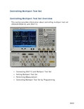
Controlling Multiport Test SetControlling Multiport Test Set OverviewThis section provides information about controlling multiport test set (E5092A/E5091A) with E5071C.▪Connecting E5071C and Multiport Test Set▪Setting Multiport Test Set▪Performing Measurement▪Controlling Multiport Test Set by ProgrammingControlling Multiport Test SetConnecting E5071C and Multiport Test Set∙Connecting E5071C (Option 440/445/460/465/480/485) and E5092A ∙Connecting E5071C (Option 4D5/4K5) and E5092A∙Connecting E5071C (Option 440/445/460/465/480/485) and E5091A ∙Connecting Two Multiport Test Sets∙Recommended WrenchOther topics about Controlling Multiport Test SetConnecting E5071C (Option 440/445/460/465/480/485) andE5092ARequired DevicesThe devices required to connect the E5071C (option440/445/460/465/480/485) to the E5092A configurable multiport test set are listed below:∙E5071C (option 440/445/460/465/480/485)∙E5092A (option 020)∙Type-N to SMA coaxial adapter (included in the E5092A-08C for connection with the E5071C, Agilent part number: 1250-2879)∙SMA semi-rigid cable (included in the E5092A-08C for connection with the E5071C, Agilent part number: E5092-61652)∙USB cable (supplied with the E5092A, Agilent part number: 8121-1695)∙For the rackmount usage, it is recommended to use semi-rigid cable (Agilent part number: E5092-61654, included in theE5092A-08C) for connection with the E5071C.USB Cable Connections and Driver Installation1.Connect the USB cable between one of USB ports on the E5071C rearpanel and that of the E5092A.2.Turn on the E5071C and the E5092A.3.The Found New Hardware Wizard appears. Select install the softwareautomatically, then click Next.E5071C4.Click Finish.Controlling Multiport Test Set 5.The Found New Hardware Wizard appears again. Select install thesoftware automatically, then click Next.6.Click Finish.E5071C7.After the E5071C detects the E5092A, the LEDs that indicate theconnected test ports remain on.8.E5071C should be reset once the multiport test set driver is updated. RF Cable Connection1.Connect the type-N to SMA adapter on the test ports (PORT 1 to 4)of the E5071C.2.Connect the SMA semi-rigid cables between the adapters on theE5071C and the test ports (PORT 1 to 4) of the multiport test set.Make the connection so that the numbers of the ENA ports and thetest set ports match.Controlling Multiport Test SetConnecting E5071C (Option 4D5/4K5) and E5092ARequired DevicesThe devices required to connect the E5071C (option 4D5/4K5) to theE5092A configurable multiport test set are listed below:∙E5071C (option 4K5)∙E5092A (option 020)∙ 3.5mm (female) to 3.5mm (female) coaxial adapter (included in the E5092A-20C for connection with the E5071C, Agilent part number:85027-60005)∙Semi-rigid cable (included in the E5092A-20C for connection with the E5071C, Agilent part number: E5092-61653)∙USB cable (supplied with the E5092A, Agilent part number: 8121-1695)∙For the rackmount usage, it is recommended to use semi-rigid cable (Agilent part number: E5092-61655, included in theE5092A-20C) for connection with the E5071C.USB Cable Connections and Driver InstallationRF Cable ConnectionE5071C1.Connect the coaxial adapter on the test ports (PORT 1 to 4) of theE5071C.2.Connect the SMA semi-rigid cables between the adapters on theE5071C and the test ports (PORT 1 to 4) of the multiport test set.Make the connection so that the numbers of the ENA ports and thetest set ports match.Connecting E5071C (Option 440/445/460/465/480/485) andE5091ARequired DevicesThe devices required to connect the E5071C (option440/445/460/465/480/485) to the E5091A multiport test set are listed below:∙E5071C (option 440/445/460/465/480/485)∙E5091A (option 009/016)∙Type-N to Type-N cable (supplied with the E5091A option 009 or 016 for connection with the E5071C, Agilent part number: 8120-4782)∙USB cable (supplied with the E5091A, Agilent part number: 8121-0770)USB Cable connections and Driver InstallationControlling Multiport Test Set 1.Connect the USB cable between one of USB ports on the E5071C rearpanel and that of the E5091A.2.Turn on the E5071C and the E5091A.3.The Found New Hardware Wizard appears. Select No, not this time,then click Next.E5071C4.Select Install the software automatically, then click Next.Controlling Multiport Test Set 5.Click Finish.6.The Found New Hardware Wizard appears again. Select No, not thistime, then click Next.29507.Select Install the software automatically, then click Next.8.Select Agilent E5091A of Location C:\windows\inf\oemxx.inf (xx isnumeric number e.g.: oem29.inf), then click Next.2951295229539. Click Finish .10. After the E5071C detects the E5091A, the LEDs that indicate theconnected test ports remain on.Do not switch on/off devices connected via the USBports (front or rear panel) or connect/disconnect devices to theUSB ports while the E5071C is measuring with the E5091A.Even if you install the driver on a USB port, you willbe asked to install driver again if you connect E5091A with adifferent USB port.RF Cable ConnectionConnect the type-N cables between the test ports (PORT 1 to 4) of the E5071C and the test ports (PORT 1 to 4) of the multiport test set. Make the connection so that the numbers of the ENA ports and the test set ports match.Connecting Two Multiport Test SetsUp to two multiport test sets can be connected to one ENA for measurements with more multiple test ports.29541.Set IDs of connected multiport test sets to different values. Theinstruments will not work correctly if their IDs are the same. Formore information, see Selecting ID for Multiport test Set.2.Press System key > Multiport Test Set Setup to display the multiporttest set setup menu.3.Select Test Set 1 for the test set with ID 1 and Test Set 2 for ID 2.4.The E5091A (option 009 and 016) and the E5092A (option 020)can be used at the same time.Recommended WrenchWhen using a semi-rigid cable, connect the semi-rigid cable to a test port of the multiport test set with a specified torque using a torque wrench.Specified torque 5.7 kgf-cm/ 56 N-cm / 5 in-lbRecommended wrench Wrench (Agilent part number 8710-1582)29552956Setting the Multiport Test SetThis section describes the settings of the multiport test set. The following table shows the flow used for item setting:Setting flow for multiport test set Item Description Selecting ID for Multiport Test SetSelects the ID of the multiport test set youwant to set Selecting the Configuration of theMultiport Test SetSelects the configuration of the multiport test set you want to set Assigning Test PortsAssigns test ports of the E5071C and those of the multiport test set Displaying the PropertiesDisplays the multiport test set property to check the port setting Setting Control Line Makes the setting of the control line thatcontrols the DUTOther topics about Controlling Multiport Test SetSelecting ID for Multiport Test SetOperational Procedure1. Set the target ID to the ID of the connected multiport test set.2. Press System key > Multiport Test Set Setup to display the multiport test set setup menu.3. Select Test Set 1 for ID 1 and Test Set 2 for ID 2. The ID is set with the bit switch on the rear panel of the multiport test set.ID Bit Switch of E5091AID Bit Switch of E5092A∙Change the ID bit switch setting while the E5071C is turned off.∙Two multiport test set can be controlled from one E5071C by assigning an ID number (ID 1 or ID 2) on each test set.∙The E5091A (option 009 and 016) and the E5092A (option 020) can be used at the same time.Selecting the Configuration of the Multiport Test SetSelect the configuration of the multiport test set you want to set. Operational Procedure1.Press System >Multiport Test Set Setup > Test Set 1 or Test Set2.2.Click Select Test Set.3.Select the configuration of the multiport test set from the followingselection:TestSoftkey ConfigurationsetE5092A E5092_13 Select the 13-port configuration of the E5092A (E5092A-020). Equivalent to E5091_13 of the E5091A-016.29572958 E5092_16Select the 16-port configuration of the E5092A (E5092A-020). Equivalent to E5091_16 of the E5091A-016. E5092_22Select the 22-port configuration of the E5092A (E5092A-020). E5092_28Select the switching independently in the E5092A (E5092A-020). E5092_X10Select the 10-port full crossbar configuration of the E5092A (E5092A-020). E5091A E5091_9Select the 9-port option of the E5091A (E5091A-009). E5091_13Select the 13-port configuration of the E5091A-016. E5091_16 Select the 16-port configuration of the E5091A-016.4. Click Control to enable (ON ) control of the multiport test set.5. The enable (ON )/disable (OFF ) setting of the control function of the multiport test set is executed for all channels.If the model you use and the selected softkey isdifferent, the configuration will not be reflected. Also, no errormessage will appear. For the correlation between the model and the softkey, refer to the following table:E5091_9 E5091_13 E5091_16 E5092_13 E5092_16 E5092_22 E5092_28 E5092_X10 E5091A(Option 009)Yes No No No No No No No E5091A (Option016)No Yes Yes No No No No No E5092A(Option020) No No No Yes Yes Yes Yes YesAssigning Test PortsBefore calibration and measurement, you need to assign the test ports of the multiport test set. You can set the connection ports for each channel and perform measurement while switching the connection for each channel.Operational Procedure1.Press System key, then click Multiport Test Set Setup > Test Set 1 orTest Set 2.2.Press Channel Next (or Channel Prev) to activate the channel forwhich you want to set the connection ports.e the corresponding softkey to assign the connected test port ofthe multport test set.4.Execute Step 2 through Step 3 for all channels for which you want toperform sweep.When the E5091_9 is SelectedSoftkey FunctionPort 1Selects a test port of the multiport test set connected to the port 1. You can select the port from A or T1.Port 2Selects a test port of the multiport test set connected to the port 2. You can select the port from T1 or T2.Port 3Selects a test port of the multiport test set connected to the port 3. You can select the port from R1+, R2+, or R3+.Port 4Selects a test port of the multiport test set connected to the port 4. You can select the port from R1-, R2-, or R3-.When the E5092_13/E5091_13 is SelectedSoftkey FunctionPort 1Selects a test port of the multiport test set connected to the port 1. You can select the port from A, T1, T2, or T3.Port 2Selects a test port of the multiport test set connected to the port 2. You can select the port from T1, T2, T3, or T4.Port 3Selects a test port of the multiport test set connected to the port 3. You can select the port from R1+, R2+, R3+, or R4+.Port 4Selects a test port of the multiport test set connected to the port 4. You can select the port from R1-, R2-, R3-, or R4-.When the E5091_16 is SelectedSoftkey FunctionPort 1Selects a test port of the multiport test set connected to the port 1. You can select the port from A1, A2, A3, A4, A, T1, T2, or T3.Port 2Selects a test port of the multiport test set connected to the port 2. You can select the port from B1, B2, B3, B4, T1, T2, T3, or T4.29592960Port 3 Selects a test port of the multiport test set connected to the port 3. You can select the port from R1+, R2+, R3+, or R4+.Port 4 Selects a test port of the multiport test set connected to the port 4. You can select the port from R1-, R2-, R3-, or R4-.Port 5 Selects a test port of the switch #13 (SW13). You can select the port fromX1 or X2.Port 6 Selects a test port of the switch #14 (SW14). You can select the port fromY1 or Y2.Port 7Selects a test port of the switch #15 (SW15). You can select the port fromZ1 or Z2. The same test ports cannot be connected to eachport. In such a case, the other test ports settings will beautomatically changed.When the E5092_16 is Selected SoftkeyFunction Port 1 Selects a test port of the multiport test set connected to the port 1. Youcan select the port from A1, A2, A3, or A4.Port 2 Selects a test port of the multiport test set connected to the port 2. Youcan select the port from B1, B2, B3, or B4.Port 3 Selects a test port of the multiport test set connected to the port 3. You can select the port from R1+, R2+, R3+, or R4+.Port 4 Selects a test port of the multiport test set connected to the port 4. Youcan select the port from R1-, R2-, R3-, or R4-.Port 5 Selects a test port of the switch #8 (SW8). You can select the port from X1or X2.Port 6 Selects a test port of the switch #9 (SW9). You can select the port from Y1or Y2.Port 7Selects a test port of the switch #10 (SW10). You can select the port from Z1 or Z2. When the E5092_22 is SelectedSoftkeyFunction Port 1 Selects a test port of the multiport test set connected to the port 1. Youcan select the port from A1, A2, A3, A4, A5,or A6.Port 2Selects a test port of the multiport test set connected to the port 2. Youcan select the port from A7, A8, A9, A10, or A11.Port 3Selects a test port of the multiport test set connected to the port 3. You can select the port from B1, B2, B3, B4, B5, or B6.Port 4Selects a test port of the multiport test set connected to the port 4. You can select the port from B7, B8, B9, B10, or B11.When the E5092_28 is SelectedSoftkey FunctionPort 1Selects a test port of the switch #1 (SW1). You can select the port from A, B, C, or D.Port 2Selects a test port of the switch #2 (SW2). You can select the port from A, B, C, or D.Port 3Selects a test port of the switch #3 (SW3). You can select the port from A, B, C, or D.Port 4Selects a test port of the switch #4 (SW4). You can select the port from A, B, C, or D.Port 5Selects a test port of the switch #5 (SW5). You can select the port from A or B.Port 6Selects a test port of the switch #6 (SW6). You can select the port from A or B.Port 7Selects a test port of the switch #7 (SW7). You can select the port from A or B.Port 8Selects a test port of the switch #8 (SW8). You can select the port from A or B.Port 9Selects a test port of the switch #9 (SW9). You can select the port from A or B.Port 10Selects a test port of the switch #10 (SW10). You can select the port fromA or B.When the E5092_X10 is SelectedSoftkey FunctionPort 1Selects a test port of the multiport test set connected to the port 1. You can select the port from 1, 3, 5, or 7.Port 2Selects a test port of the multiport test set connected to the port 2. You can select the port from 2, 4, 6, or 8.29612962 Port 3 Selects a test port of the multiport test set connected to the port 3. Youcan select the port from 2, 4, 6, or 10.Port 4Selects a test port of the multiport test set connected to the port 4. You can select the port from 1, 3, 5, or 9. Displaying the PropertiesBy displaying the multiport test set properties shown below, you can obtain the assignment information of the test ports for each channel. This is useful when you need to check the test port assignment, for example, when you perform calibration.Multiport Test Set propertiesOperational Procedure1. Press System Key, then click Multiport Test Set Setup > Test Set 1 or Test Set2.2. Click Property to enable it (ON ) to display the multiport test set's properties.The enable (ON )/disable (OFF ) setting of themultiport test set properties display is executed for all channels.Setting Control LineThe E5071C can control the output from the control line of the multiport test set and control the DUT (for example, switching the frequency band of the front end module).E5092A Front PanelE5092A Control Line29632964E5091A Front PanelOperational Procedure1.Press System Key, then click Multiport Test Set Setup > Test Set 1 orTest Set 2.2.Press Channel Next (or Channel Prev) to activate the channel forwhich you want to set the control line.3.Click Control Lines for E5091A or Control Line A/B/C/D for E5092A todisplay the settings menu for the DUT control line.e the corresponding softkey to set the control line of the multiporttest set.Softkey FunctionHigh/Low of each line of the control line.Line 1 to Line 8 SetDC source (only for E5092A) Set DC source voltage.5.Execute Step 3 through Step 4 for all channels that you want tosweep.2965Performing Measurement∙Calibration∙Making MeasurementsOther topics about Controlling Multiport Test SetCalibrationFollow these steps to perform calibration with the multiport test set connected:1.Press Channel Next (or Channel Prev) key to set the channel that youwant to calibrate to the active channel.2.Follow Displaying the properties to display the multiport test setproperties.3.Perform the calibration. Check the corresponding multiport test settest ports shown in the calibration properties as the port names ofthe E5071C are displayed on the calibration menu, connect thecalibration standard to the corresponding test ports of the multiporttest set, and perform the calibration.Making MeasurementsMaking measurements with multiport test set is the same as E5071C standalone measurement. Perform operations by referring to Making Measurements.Trigger state and switching the setting of the Multiport test setThe following table shows how the setting in the multiport test set is switched from when the trigger state is the stop state.Trigger state Switching the setting of multiport test setStop The setting is not switched.Trigger wait The setting of the internal switch and the output of the control lineare switched according to the setting of the channel swept first.The connections of the test ports and the output of the control lineare switched according to the setting of the channel swept first. Measurement Measurement is performed following the procedure below.1.Execute a sweep for the first channel.2.Set the connections of the test ports and the output of thecontrol line according to the settings of the channel sweptsecond.29663.Execute a sweep for the second channel.4.Set the connections of the test ports and the output of thecontrol line according to the setting of the channel swept last.5.Execute a sweep for the last channel.Stop or trigger wait The setting is not switched for the stop state; it is switched for the trigger wait state.2967Controlling Multiport Test Set by Programming∙Selecting Test Set∙Selecting ports assigned to Port 1 to Port n∙Difference between E5092A and E5091A∙Sample programOther topics about Controlling Multiport Test SetSelecting Test SetThe multiport test set provides test set 1 and test set 2. To select the test set, use the following command::SENS:MULT{1-2}:NAMEThe following models are available for the test set:Multiport Test Set OptionE5092A E5092_13 Option 020 (13-port measurement)E5092_16 Option 020 (16-port measurement)E5092_22 Option 020 (22-port measurement)E5092_28 Option 020 (28-port measurement)E5092_X10 Option 020 (X10-port measurement)009E5091A E5091_9 OptionE5091_13 Option 013 (13-port measurement)E5091_16 Option 016 (16-port measurement)Checking the name of available test setTo check the name of the available multiport test set, use the following command::SENS:MULT:CAT?Turning control ON/OFFTo turn ON/OFF the control of the multiport test set, use the following command::SENS:MULT{1-2}:STAT2968If you turn OFF the control of the multiport test set, it does not affect the operation of the E5071C, even if it is connected. You can control test set 1 and test set 2 separately.Selecting ports assigned to Port 1 to Port nSelecting the connection portsYou can select the ports assigned to Port 1 to Port n for each channel. To select the ports, use the following commands::SENS{1-36}:MULT{1-2}:PORT{1-20}The connection between the assigned ports and Port1 to Port n inside the E5091A is not changed when one of theabove commands is executed but it is changed immediatelybefore a sweep for each channel.Turning ON/OFF state display of connection ports (properties display)You can display the state of the ports assigned to Port 1 to Port n (multiport test set properties) in the lower right part in the window for each channel. To turn ON/OFF the properties display, use the following command::SENS:MULT{1-2}:DISPChecking number of portsTo check the number of the multiport test set connected ports, use the following command::SENS:MULT{1-2}:COUN?Checking the available port nameTo check the name of the multiport test set connected ports, use the following command::SENS:MULT{1-2}:PORT{1-20}:CAT?Checking number of input portsTo check the number of the multiport test set input ports, use the following command::SENS:MULT{1-2}:INC?Setting control lineYou can set the HIGH/LOW state of each line of the control line for each channel. To set the HIGH/LOW of each line, use the following command::SENS:MULT{1-2}:TSET9:OUTPThe HIGH/LOW state of each line of the E5091A is not changed when the above command is executed but it ischanged immediately before a sweep for each channel.2969E5071C2970 Difference between E5092A and E5091ADifference E5092AE5091A Options13 port, 16 port, 22 port, 28 port and X10 port 9 port, 13 port and 16 port Number of control lines 2 1The channel number for E5092A has increasedbecause the number of supported test sets has increased.Controlling E5092AThe following commands are available only inE5092A. Setting output data/voltage and switchTo set the value of output data/voltage and switch, use the following command::CONT:MULT[1-2]:OUTP:[A-D][:DATA]:CONT:MULT[1-2]:OUTP:[A-D]:VOLT[:DATA]:CONT:MULT[1-2]:PORT[1-20][:SEL]:SENS[1-160]:MULT[1-2]:OUTP[:DATA]:SENS[1-160]:MULT[1-2]:OUTP:[A-D][:DATA]:SENS[1-160]:MULT[1-2]:OUTP:[A-D]:VOLT[:DATA]:SENS[1-160]:MULT[1-2]:PORT[1-20][:SEL]Selecting test setTo select the test set, use the following command::SENS[1-160]:MULT[1-2]:NAMEFor E5091A test set, only the following two commands are available: :CONT:MULT[1-2]:PORT[1-20][:SEL]:CONT:MULT[1-2]:OUTPut:A[:DATA]Sample programSee Control E5091A.。
网络分析仪E5071C帮助文档_三种操作方法

屏幕区域:元件的名称和功能通道窗口用于显示迹线的窗口。
因为一个通道对应于一个窗口,所以称之为通道窗口。
通道窗口的外框显示为浅灰色时,通道为工作通道(正在为该通道执行设置)。
在下图中,通道 1(上方窗口)为工作通道。
要使通道成为工作通道,请使用“Channel Next”(下一通道)或“Channel Previous”(上一通道)键。
在通道窗口内部单击也可使通道成为工作通道。
通道 1 窗口通道 2 窗口5-1. 通道标题栏可以为每个通道分配标题,并将标题显示在标题栏上。
有关设置通道标题栏的更多信息,请参见为窗口添加标记。
5-2. 迹线名/测量参数此处显示了通道上迹线的名称(Tr1 至 Tr9)及其测量参数。
迹线名右侧的 指示该迹线为工作迹线(正在为该迹线执行设置)。
要使迹线成为工作迹线,请使用“Trace Next”(下一迹线)或“Trace Prev”(上一迹线)键。
单击迹线名所在的线(鼠标指针从 更改为 )也可使迹线成为工作迹线。
5-3. 数据格式此处显示了每条迹线的数据格式。
有关设置数据格式的更多信息,请参见选择数据格式。
5-4. 刻度设置此处显示了每条迹线的刻度设置。
本示例说明“10.00dB/”对应每分度 10 dB。
“Ref 0.000dB”说明参考线的值为0 dB。
有关设置刻度的更多信息,请参见设置刻度。
5-5. 迹线状态区域此处显示了每条迹线的设置。
迹线状态显示分类 [ ] 内的内容 含义误差校正 RO 误差校正:开(开路 (n) 响应校准)RS 误差校正:开(短路 (n) 响应校准)RT 误差校正:开(直通 (n) 响应校准)ER 误差校正:开(增强的响应校准)F1误差校正:开(1 端口校准)F2 误差校正:开(全 2 端口校准/2 端口TRL 校准)F3 误差校正:开(全 3 端口校准/3 端口TRL 校准)F4 误差校正:开(全 4 端口校准/4 端口TRL 校准)打开/关闭迹线Nothing 数据迹线:开;存储迹线:关M 数据迹线:关;存储迹线:开D&M 数据迹线:开;存储迹线:开关 数据迹线:关;存储迹线:关执行数据计算 D+M (D+M&M) 执行 Data+Mem 计算存储迹线为“ON”(开)时,请参见() 内的内容D- M (D- M&M) 执行 Data- Mem 计算D*M (D*M&M) 执行 Data*Mem 计算D/M (D/M&M) 执行 Data/Mem 计算电延迟 Del 为电延迟或相位偏移指定一个非 0(零)的数值。
Aglient(E5071C)网络分析仪校准

校准
执行校验--Done校准来自VSWR驻波比设定—format--SWR格式
比例设定--Scale设定Y轴为5
保存测试环境
保持测试环境—Save—file dialog--save
VSWR测试
连接高频测试头,取制品进行VSWR测试
The End! THKS~
401校准calcalibrate1portcal校准还接校准器的openopen还始open校准校准还接校准器的shortshort还始short校准校准还接校准器的matchload还始load校准校准vswrformatswr格式
Aglient(E5071C) 网络分析仪校准
制成:赵静 审核:陈娜 时间:2011.12.16
摘要:
• 还原初始设定 • 选择校验通道 • 参数设定 • 校准 • 保存测试环境 • VSWR测试
还原初始设定
按绿色的Preset按钮还原初始值
选择校验通道
选择信号传输方式--Meas
参数设定
模式设定--Format,选中smith R+jx
参数设定(FE1058)
起始频率设定--start:500MHz
参数设定
终止频率设定--stop值:3GHz
参数设定
扫描点数设定--Sweep Setup:401
校准
校准– Cal—Calibrate—1-port cal
校准
连接校准器的Open端口连接,点击open开始open校准
校准
连接校准器的short端口连接,点击short开始short校准
校准
广凯讯ENA系列网分E5071C使用手册

深圳市龙华新区民治梅龙路南贤商业广场 13A
深圳市广凯讯通信技术有限公司
Format: (格式设定) Log Mag: Y 轴以对数形式显示振幅,X 轴显示频率 Phase: Y 轴以对数形式显示相位,X 轴显示频率 Group Delay: Y 轴以对数形式显示群时延,X 轴显 示频率 Smith: 史密斯圆图的格式设置 Polar: 极性图的格式设置 Lin Mag: Y 轴以线性形式显示振幅,X 轴显示频率 SWR: Y 轴显示驻波比,X 轴显示频率 Real: : Y 轴显示实部,X 轴显示频率 Imaginary: : Y 轴显示虚部,X 轴显示频率 Expand Phase: Y 轴显示扩展相位,X 轴显示频率 Positive Phase: Y 轴显示正相位,X 轴显示频率 Sweep Setup: (扫描设定) Power: 打开激励信号输出设置菜单 Power: 设置网络分析仪内部信号源的输出电平 Power Ranges: 选择电平范围 Port Couple: 在现有电平上打开/关闭端口耦合 Port Power: 当端口耦合关闭时设置端口功率 CW Freq: 设置功率扫描的固定频率 RF Out: 开/关激励源的输出 Sweep Time: 设置端口扫描时间 Sweep Delay: 设置扫描延时 Sweep Mode: 选择扫描模式 Points: 设置每次扫描的扫描点数 Sweep Type: 选择扫描类型 Edit Segment Table: 编辑段扫描设置表 Freq Mode: 切换频率设置模式 List IFBW: 在分段表中显示/不显示中频带宽 List Power: 在分段表中显示/不显示功率 List Delay: 在分段表中显示/不显示延时 List Sweep Mode: 在分段表中显示/不显示扫描模式 List Time: 在分段表中显示/不显示扫描时间 Delete: 删除表项 Add: 增加表项 Clear Segment Table: 清除分段表 Export to CSV File: 将限制表格输出以 CSV 文件 格式保存 Import from CSV File: 从 CSV 格式文件中输入限 制表格 Avg: (平滑设定) Averaging Restart: 复位计数器从 1 开始 Avg Factor: 设置均衡因子 Averaging: 开启/关闭平滑功能 Smoothing: 开启/关闭平整功能 IF Bandwidth: 设置中频带宽 Cal: (校验设定) Correction: 开启/关闭错误修正 Calibrate: 校验菜单 Response (Open): 开路响应校验选择菜单 Select Port: 选择端口 Open: 对选定端口进行开路条件下的响应校验(用于 消除响应跟踪误差) Load (Optional): 对选定端口进行负载条件下的隔 离度校验(用于消除方向性误差) Done: 终止校验进程并计算校验系数 Response (Short): 短路响应校验选择菜单 Select Port: 选择端口 Short: 对选定端口进行短路校验(用于消除反射跟 踪误差) Load (Optional): 对选定端口进行负载条件下的隔 离度校验(用于消除方向性误差) Response (Thru): 传输响应校验选择菜单 Thru: 对选定端口进行传输响应校验(用于消除传 输跟踪误差) Isolation (Optional): 对选定端口进行隔离度校 验(用于消除隔离度误差) 1-Port Cal: 单个端口校验菜单 Select Port: 选择端口 Open: 对选定端口进行开路校验 Short: 对选定端口进行短路校验 Load: 对选定端口进行负载校验 Done: 终止校验进程并计算校验系数 2-Port Cal: 双端口校验菜单 Select Ports: 选择端口 Reflection: 反射校验菜单 Transmission: 传输校验菜单 Isolation (Optional): 隔离度校验菜单 Done: 终止校验进程并计算校验系数 ECal: 电子校验菜单 1—Port ECal: 单端口电子校验 2—Port ECal: 双端口电子校验 Thru ECal: 传输电子校验 Isolation: 开启/关闭隔离度校验功能 Characterization: 电子校验特性选择菜单
使用指南
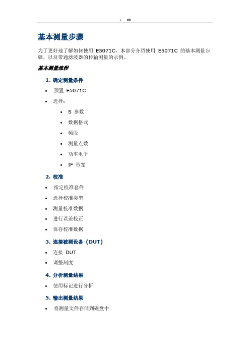
基本测量步骤为了更好地了解如何使用E5071C,本部分介绍使用E5071C 的基本测量步骤,以及带通滤波器的传输测量的示例。
基本测量流程1.确定测量条件∙预置E5071C∙选择:∙S 参数∙数据格式∙频段∙测量点数∙功率电平∙IF 带宽2.校准∙指定校准套件∙选择校准类型∙测量校准数据∙进行误差校正∙保存校准数据3.连接被测设备(DUT)∙连接DUT∙调整刻度4.分析测量结果∙使用标记进行分析5.输出测量结果∙将测量文件存储到磁盘中前面板:元件的名称和功能1. 待机开关∙用于在E5071C 的开机( | ) 和待机(O) 状态之间进行选择。
要关闭E5071C 的电源,请确保遵循下面描述的步骤:1.首先,按此待机开关或从外部控制器发送关机命令,以启动关机过程(关闭电源所必需的软件和硬件处理)。
这将使E5071C 进入待机状态。
2.其次,如有必要,请关闭后面板上电源的电源线插座(接电源线)。
∙在正常使用情况下,请勿在电源接通时直接断开后面板上电源线插座的电源。
始终将线路开关(始终接通)保持为(|)。
请勿将其关闭(O)。
如果在电源接通时直接断开电源线插座的电源,或者关闭线路开关(始终接通),则关机过程将无法进行。
这可能会损坏E5071C的软件和硬件,并导致设备故障。
在错误关机后接通电源,可能引起系统在所谓的“安全模式”的条件下启动。
如果出现此情况,首先关闭系统使其进入待机状态,然后再次接通电源,以便在正常模式下启动系统。
2. LCD 屏幕E5071C 配备有10.4 英寸TFT 彩色触敏式LCD 屏幕,用于显示迹线、刻度、设置、功能键以及其他与测量相关的信息。
借助触摸屏LCD,直接用手指触摸LCD 屏幕即可操纵功能键。
有关LCD 屏幕的更多信息,请参见屏幕区域:元件的名称和功能。
∙不要使用尖锐物体(例如,钉子、钢笔或改锥)按压LCD 屏幕的表面。
使用尖头物体按压表面会损坏LCD 屏幕的表面或导致屏幕故障。
E5071C网络分析仪测试方法

"E5071C网络分析仪测试方法一.面板上常使用按键功能大概介绍如下:Meas 打开后显示有:S11 S21 S12 S22 (S11 S22为反射,S21 S12 为传输)注意:驻波比和回波损耗在反射功能测试,也就是说在S11或者S22里面测试。
Format 打开后显示有:Log Mag———SWR———-里面有很多测试功能,如上这两种是我们常用到的,Log Mag为回波损耗测试,SWR 为驻波比测试。
Display打开后显示有:Num of Traces (此功能可以打开多条测试线进行同时测试多项指标,每一条测试线可以跟据自己的需求选择相对应的指标,也就是说一个产品我们可以同时测试驻波比和插入损耗或者更多的指标)Allocate Traces (打开此功能里面有窗口显示选择,我们可以跟据自己的需求选择两个窗口以上的显示方式)Cal 此功能为仪器校准功能:我们常用到的是打开后在显示选择:Calibrate(校准端口选择,我们可以选择单端口校准,也可以选择双端口校准)Trace Prev 此功能为测试线的更换设置Scale 此功能为测试放大的功能,打开后常用到的有:Scale/Div10DB/Div 为每格测试10DB,我们可以跟据自己的产品更改每格测量的大小,方便我们看测试结果Reference Value 这项功能可以改变测试线的高低,也是方便我们测试时能清楚的看到产品测试出来的波型。
Save/Recall 此功能为保存功能,我们可以把产品设置好的测试结果保存在这个里面进去以后按下此菜单Save State 我们可以保存到自己想保存的地方,如:保存在仪器里面请按Recall State 里面会有相对应的01到08,我们也可以按SaveTrace Data 保存在外接的U盘里面,方便的把我们产品的测试结果给客户看。
二.仪器测试的设置方法1.频率设置:在仪器面板按键打开Start 为开始频率,Stop 为终止频率。
ENA 作业指导书
设置测试条件设置激励条件按“Start”(开始)键,然后输入10 MHz。
按“Stop”(结束)键,然后输入 6 GHz。
设置响应条件按“AVG”(平均)键,然后在“IF Bandwidth”(IF 带宽)输入设置测试参数差模设置按“Analysis”(分析)键。
单击“Fixture Simulator”(夹具仿真器)>“Topology”(布局)>b9.将两端测试治具第一对分别与端口1-2和3-4相连,然后将待测物连接到治b11.按“System”(系统)>“Dump Screen Image”(转储屏幕图像)打开“Save As”(另存为)对话框。
单击“Save”(保存)将屏幕图像保存到文件中。
回波损耗按“Meas”(测量)键,选择Sdd11。
将一端测试治具第一对与端口1-2相连,另一端测试治具第一对接阻,然后将待测物连接到治具上。
(连接方式详见下图)按“Marker”(标记)键。
这时,标记 1 打开并变成工作标记(即可以操作此标记)远端串扰按“Meas”(测量)键,选择Sdd21。
将一端治具第一对和另一端治具第二对分别与端口1-2和3-4相连,然后将一端治具第二对和另一端治具第一对分别接50Ω标准电阻,然后将待测物连接到治具上。
(连接方式详见下图)按“Marker”(标记)键。
这时,标记 1 打开并变成工作标记(即可以操作此标记)“System”(系统)>“Dump Screen Image”(转储屏幕图像)打开“Save As”(另存为)对话框。
单击“Save”(保存)将屏幕图像保存到文件中。
矢量网络分析仪使用方法
Confidential
2:选择Calibration
Vanchip Confidential
Confidential
3:选择两端口校准
Vanchip Confidential
Confidential
4:先做Reflection校准
Vanchip Confidential
Confidential
依次做好以上六步校 准后Return
Vanchip Confidential
Confidential
5:接着做 Transmission校准
Vanchip Confidential
Confidential
1-2端口直通校准
12
先把1和2端口通过 双阴SMA头连接上。
再在面板上按对应 Port1-2 Thru键执行校 准动作
Vanchip Confidential
Confidential
校准状态储存SAVE和Recall
按Save键,存储校准好的 状态。便于以后调用。
按Recall键,调用之前存 储好的校准状态。
Vanchip Confidential
Confidential
储存为自建文件---可长期使用
存储为自建文件名
第一步:校准仪器(包括固定线缆)
Vanchip Confidential
Confidential
矢网的手动配件(校准件型号)
校准件型号
Open Short Load Thru
Vanchip Confidential
Confidential
矢网的配件(线缆)
线缆为HUBBER+SUHNNER品牌
Confidential
e5071c技术参数及选型
选件...................................................................................................................................... 3 定义...................................................................................................................................... 4 边界条件 .............................................................................................................................. 4 校正后的系统性能............................................................................................................... 5
系统动态范围 ...................................................................................................................... 5 校正后的系统性能, 使用校准套件 ........................................................................................... 7 未校正的系统性能 ...................
E5071C作业指导书0928
根据中a的步骤进入 limited 设定菜单.在旋转光标旋转到将 要更改的数值上,按 Analysis点击 Limit Test ,点击 Edit Limit Line ,输入新 Marker1 频率值,再按 Enter 键,点击 Begin Response/End Response ,根据中的要求输入数值, 如此更改上限 LIMIT 值的值.
1.目的 Purpose 1.1指导RF测试工位进行天Limited设定; 1.2通过RF测试工位检测天线产品的一致性,保证天线品 质;
1.3指导RF测试工位的操作手法. 2.应用范围 Scope 此说明书应用于以Agilent E5071C网络分析仪来测量的 RF测试工位的操作. 3.参考文件 Reference
放映结束 感谢各位的批评指导!
谢 谢!
让我们共同进步
• 6.1按下〔如图1中所示键1开机,系统开始启动;
•
6.2设定标准天线被测谐振点;
•
被测点limited设定标准;
•
每个被测点设定三对limited点〔谐振点上
设定一对,3dB驻波点上各设一对,如下图2
图2
当天线频段<1GHz,在其中心频点±300MHz范内选取一个谐 振点,做为被测频点;
当天线频段≥1GHz,在其中心频点±400MHz范内选取一个谐 振点,做为被测频点;
被选取的谐振点,驻波比要求小于2.5dB\3dB带宽要求大于 40MHZ,小于120MHz;
每对limited的上下Offset值为0.5dB〔VSWRMarker2< 1.5dB时,下限limited直接设在1dB;
、Marker3驻波比偏差要求在3dB±0.2dB之内.
选取标准样被测点
按 PRESET 键再按Enter仪器进入预设状态
- 1、下载文档前请自行甄别文档内容的完整性,平台不提供额外的编辑、内容补充、找答案等附加服务。
- 2、"仅部分预览"的文档,不可在线预览部分如存在完整性等问题,可反馈申请退款(可完整预览的文档不适用该条件!)。
- 3、如文档侵犯您的权益,请联系客服反馈,我们会尽快为您处理(人工客服工作时间:9:00-18:30)。
41 msec
848 msec
测量速度对比: 1601 点,全二端口校准,1 GHz 至 1.2 GHz IF 带宽 = 6 kHz (8753ES),500 kHz (E5071C)
5
增强的测量功能可以适用于这种类型的测试需求
安捷伦 E5071C ENA 将最佳 RF 性能与强大的分析能力 和自动化测试工具结合在一起,显著地提高了测试效率和 生产率。
应用指南: Evolution of Test Automation Using the Built-In VBAwith the ENA Series RF Network Analyzers, 5988-6192EN
简便、准确的夹具内校准
减少测量误差 在多端口校准时,一次可以进行 4 个端口的 TRL 校准 自动端口扩展 (APE) 功能可以让某些校准更加简便 适配器去除/插入功能可以帮助用户自己定制非常专用和 特殊的电子校准件
ENA 为准确表征这些器件的特性提供了几种测试方法。 相对于传统的校准方法,安捷伦更先进的校准技术,包括矢量 混频器校准 (VMC) 的专利技术可以为您的器件提供更准确的 测量结果。
变频损耗
标量混频器校准
功率计校准
校准混频器 / 滤波器
混合式巴伦
强大的内置软件功能 缩短设置与测量时间
频率偏移模式 (FOM) (选项) 差分混频器测量 绝对群延迟测量 简便易用的分析软件 缩短您的操作时间 混频器测量向导程序 矢量混频器特性表征程序
1. 测量速度是在全二端口校准和 1601 个测试点的情况下获得的。 2
22 端口
16 端口
适应各种类型应用的灵活的测试端口
选择适合您的应用的端口数目、测试频率范围以及是否需要 Bias-T
端口数 9 kHz 100 kHz 300 kHz 50 MHz
频率范围 4.5 GHz 8.5 GHz
带 Bias-Bias-T
内置 VBA 编程和可定制的用户界面
业内最新的校准技术 多达全部 4 端口 SOLT、TRL 或未知直通校准 自动端口扩展 适配器参数的去除或插入 电子校准件 (Ecal) 可配置成各种连接头的形式,甚至可以 与任意适配器组合使用成为特殊专用的电子校准件 标量混频器校准和获得专利的矢量混频器校准 2
安捷伦 E5071C ENA 矢量网络分析仪
9 kHz 至 4.5 GHz 100 kHz 至 4.5 GHz (带 Bias-T ) 9 kHz 至 8.5 GHz 100 kHz 至 8.5 GHz (带 Bias-T ) 300 kHz 至 20 GHz (带 Bias-T )
RF 网络分析的行业标准
2 端口
带 Bias-T 带 Bias-T
4 端口
带 Bias-T
带 Bias-T 带 Bias-T
选件
20 GHz E5071C-240 E5071C-245 E5071C-280 E5071C-285 E5071C-2K5
E5071C-440 E5071C-445 E5071C-480 E5071C-485 E5071C-4K5
业内领先的 RF 性能 让您充满自信地设计高性能产品
业内最新校准技术保证最高的测量精度 用于夹具内器件测试的自动端口扩展 夹具仿真可以把用户自定义的电路参数进行嵌入或去嵌入
应用指南: Network Analysis * Calibration-Specifying CalibrationStandards and Kits for Agilent Network Analyzers, AN 1287-11, 5989-4840EN 应用指南: Network Analysis * De-embedding and EmbeddingSparameter Networks Using a Vector Network Analyzer, AN 1364-1, 5980-2784EN
ENA 具有实时夹具仿真功能,这个功能可以让您详细表 征当器件工作在实际应用电路的环境中所具有的特性。VBA 是和ENA捆绑在一起提供的编程工具,这种宏处理与分析功能 支持快速、简便的数据后处理。测得的数据可以方便地与 安捷伦先进设计系统 (ADS) 共享。这样可以使您快速把测量 结果回馈到仿真环境,以改进设计并加速设计验证的过程。
E5071C 动态范围对比: IF 带宽 = 10 Hz
8753ES
低迹线噪声 在 IFBW 为 70 kHz 时, 迹线噪声不到 0.004 dB rms, 当测量高 Q 、低损器件时, 这有助于将误差降至最小。
E5071C 迹线噪声对比: IF 带宽 = 1 kHz
8753ES
高稳定性
快速测量速度
同类型产品中最大的 (10.4 英寸) XGA 彩色 LCD 触摸屏
160 个测量通道和 直观的用户界面: 面板按键、 保护数据安全的
16 条测量迹线
功能选择键和下拉菜单
可拆卸硬盘 (可选)
开放式 Windows ® 操作系统
两个支流供电接口
内置帮助文件随时按需 提供帮助信息
ENA 直观的用户界面让您 很容易就可以完成复杂的 测量设置,快速检索测量 数据。
其长期温度稳定性优于 8753ES 的 4倍, 这意味着您可以充分信赖 您的测量结果的准确性。
比8753ES的速度快20多倍, 大大提高了测试效率, 可以帮助提高 产量, 并降低每一器件的平均成本。
E5071C 8753ES
0.005 dB/°C
稳定性随温度的变化
ห้องสมุดไป่ตู้0.02 dB/°C
E5071C 8753ES
测试自动化工具 简便易用的内置式VBA编程环境,用于快速的数据后处理 用于多端口测量系统的测量向导助手 (MWA) 软件 (可选) 用于“通过 / 失败”测试的预定义指标限制线测试功能
1. 需要 4 端口选件。 2. 需要 E5071C-008 频率偏移模式。
6
■ 准确而高效的器件设计与验证
电路
ENA 集测试速度、测量精度、先进的功能于一身,它是 一个进行矢量网络分析所必用的功能强大的通用仪表。同时, ENA 丰富的测试功能、数据分析特性和数据后处理能力也使 它成为器件设计性能验证分析测试的有力工具。
强大的数据处理功能 快速、简便地对测量数据进行后处理
放大器测量向导程序 用于用户自定义参数的公式编辑器
简便的软件连接性 将测量结果快速反馈链接到您的仿真环境中
Intuilink 软件 与 ADS 相连接
9
■ 最先进的测量功能
混频器与变频器件测试
在许多应用中都会用到诸如混频器之类的频率变换器件。 由于这些器件输入和输出端口的频率不同,所以他们需要 独特的测量技术。
■ 用 ENA 多端口解决方案扩展您的测量功能
多端口器件测试
现在的器件经常将多种功能集成在一个器件中,具有多 个RF端口的器件也越来越常见。在进行多端口矢量网络分析 的时候,对测量进行设置的时间通常远长于实际测试所花的 时间。
安捷伦功能强大的综合多端口测试解决方案由 ENA 和 E5092A 可配置多端口测试扩展设备构成。ENA 的多端口 测量向导助手 (MWA) 软件简化了多端口器件特性表征的复杂 的测量过程。
高性能电校准件 (Ecal) 使校准过程大位简化
使用设置向导软件进行夹具仿真的设置
阻抗值显示
强大的分析功能
夹具仿真器用于 ● 混合模式 S 参数测量 1 ● 嵌入与去嵌入 ● 匹配电路仿真 ● 端口阻抗转换 实时数据处理的公式编辑器 时域分析 (可选) 绝对值测量 75 ohm 测量 (需要损耗很小的阻抗变换器) 使用安捷伦 ADS 和 IC-CAP 对元件进行建模 用安捷伦材料测量软件进行介电常数和导磁率测量
E5071C-440 或 -445 E5091A-016 E5071C-480 或 -485 E5091A-016
E5071C-440 或 -445 E5092A E5071C-480 或 -485 E5092A E5071C-4K5 E5092A
3
可用性的增强提高了产品研发与制造的效率
安捷伦 ENA 网络分析仪提供最前沿的现代化技术,向 您提供能满足各种产品研发与制造过程中测试所需要的性能 与功能。
8
■ 基本和高级测试工具保证器件特性的全面表征
放大器测试
RF 放大器广泛应用于各行各业。无论是用在无线通信 系统设备、医疗仪器还是汽车电子中的放大器,对其性能的 充分表征始终是整个系统设计与验证过程的一个重要步骤。
ENA 颇具特色地体现了 1 dB 压缩点、PAE 或 K 参数的 基本测量原理,它用先进的测试技术和丰富的内置的功能 简化了对放大器全部特性进行表征的过程。
同类最佳的 RF 性能 提高测试效率, 减少总测试成本
快速测量 VBA 编程工具使自动化测试和数据处理简单又迅速 预定义的指标限制线测试功能可进一步满足您的测试需求 分段扫描功能,优化激励设置 电子校准件,显著缩短校准时间
高度可信的测试结果提高出品率 性能卓越的的测量性能提高产品出品率
低迹线噪声 宽动态范围 高温度稳定性
随时进行升级,增加新的硬件或软件 7
■ 用业内领先的 RF 性能保证最高的测试效率和产品出品率
无源器件
ENA 非常适用于无源器件的大批量生产测试。优异的 测量性能有助于实现最高的测试效率,从而提高您的生产率。 对同一器件的参数进行反复测试的结果的高度一致性和稳定性 可极大地提高大批量生产环境中测试的可信度。
ENA — 速度、精度和通用性的新标准
安捷伦的 ENA 矢量网络分析仪为 RF 网 络分析提供了速度、精度和通用性的新标准。 由于设计了大量用以满足多种网络分析需要 的测量功能,ENA 为无线通信、通用电子、 军工和航空航天电子、汽车电子、半导体和医 疗器件等行业的器件和器件的制造与研发应 用提供了高效和灵活的测试手段。