海迈克伺服驱动器说明书
2HSS57-A-XX 混合式步进伺服驱动器 用户手册说明书
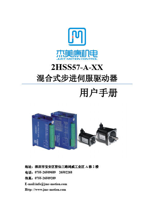
2HSS57-A-XX混合式步进伺服驱动器用户手册地址:深圳市宝安区留仙三路鸿威工业区A栋2楼电话:*************26502268传真:*************E-mail:*******************Http: //本手册的所有内容,著作财产权归深圳市杰美康机电有限公司所有,未经深圳市杰美康机电有限公司许可,任何单位或个人不得随意仿制、拷贝、撰抄。
本手册无任何形式的担保、立场表达或其它暗示。
如有本手册所提到的产品的信息,所引起的直接或间接的资料流出,导致利益损失后果,深圳市杰美康机电有限公司与所属员工不承担任何责任。
除此以外,本手册提到的产品及其资料仅供参考,内容如有更新,恕不另行通知。
版权所有,不得翻印。
深圳市杰美康机电有限公司- 2 -目录一、概述 ................................................................................ - 4 -二、特点 ................................................................................ - 4 -三、端口说明 ........................................................................ - 5 -3.1 ALM信号输出端口.................................................. - 5 -3.2控制信号输入端口.................................................. - 5 -3.3编码器反馈信号输入端口...................................... - 6 -3.4功率端口.................................................................. - 7 -四、技术指标 ........................................................................ - 8 -五、控制信号接线 ................................................................ - 9 -5.1 控制信号单端共阳极接线..................................... - 9 -5.2 控制信号单端共阴极接线................................... - 10 -5.3 控制信号差分接线方式....................................... - 11 -5.4 232串口通信接线图............................................ - 12 -5.5 控制信号时序图................................................... - 12 -六、细分拨码开关设定 ...................................................... - 13 -6.1输入沿设定............................................................ - 13 -6.2逻辑方向设定........................................................ - 14 -6.3细分设置................................................................ - 14 -七、错误报警及LED灯闪烁次数 ...................................... - 15 -八、安装尺寸 ...................................................................... - 16 -九、接线图 .......................................................................... - 17 -十、参数设置 ...................................................................... - 18 -十一、常见问题及故障处理 .............................................. - 22 -11.1 电源灯不亮......................................................... - 22 -11.2上电亮红灯报警.................................................. - 22 -11.3 运行转动一小角度后亮红灯报警..................... - 22 -11.4 脉冲输入后不转动............................................. - 23 -- 3 -一、概述2HSS57-A-XX混合式步进伺服驱动系统是在数字步进驱动中完美融合了伺服控制技术,产品采用光学编码器,每50微秒高速采样位置反馈,一旦出现位置上的偏差可立即修正位置偏差量。
100HA系列伺服驱动器使用说明书

6.2 第 2 层···································································································45 6.2.1 监视方式 ·····················································································45 6.2.2 参数设置 ·····················································································47 6.2.3 参数管理 ·····················································································47 6.2.4 速度试运行 ·················································································50 6.2.5 JOG 运行 ·····················································································50
第 6 章 显示与键盘操作·····················································································44 6.1 第 l 层····································································································44
Mini Maestro 12-通道USB伺服控制器(部分套件)说明书

Mini Maestro 12-Channel USB Servo Controller (Partial Kit)Getting started with the Maestro Servo ControllerOverviewMaestro family of USB servo controllers: Mini 24,Mini 18, Mini 12, and Micro 6.The Mini Maestros are the newest of Pololu’s second-generation USB servo controllers, offering more channels and features than the smaller six-channel Micro Maestro. The Mini Maestros are available in three sizes, and they can be purchased fully assembled or as partial kits: Mini Maestro 12 — fully assembledMini Maestro 12 — partial kitMini Maestro 18 — fully assembledMini Maestro 18 — partial kitMini Maestro 24 — fully assembledMini Maestro 24 — partial kitThe Mini Maestros are highly versatile (and compact) servo controllers and general-purpose I/O boards. They support three control methods: USB for direct connection to a computer, TTL serial for use with embedded systems, and internal scripting for self-contained, host controller-free applications. The channels can be configured as servo outputs for use with radio control (RC) servos or electronic speed controls (ESCs), as digital outputs, or as analog/digital inputs. The extremely precise, high-resolution servo pulses have a jitter of less than 200 ns, making these servo controllers well suited for high-performance applications such as robotics and animatronics, and built-in speed and acceleration control for each channel make it easy to achieve smooth, seamless movements without requiring the control source to constantly compute and stream intermediate position updates to the Mini Maestros. The Mini Maestros also feature configurable pulse rates from 1 to 333 Hz and can generate a wide range of pulses, allowing maximum responsiveness and range from modern servos. Units can be daisy-chained with additional Pololu servo and motor controllers on a single serial line.The Status tab in the Maestro Control Center.A free configuration and control program is available for Windows and Linux, making it simple to configure and test the device over USB, create sequences of servo movements for animatronics or walking robots, and write, step through, and run scripts stored in the servo controller. The Mini Maestros’ 8 KB of internal script memory allows storage of up to approximately 3000 servo positions that can be automatically played back without any computer or external microcontroller connected.Because the Mini Maestros’ channels can also be used as general-purpose digital outputs and analog or digital inputs, they provide an easy way to read sensors and control peripherals directly from a PC over USB, and these channels can be used with the scripting system to enable creation of self-contained animatronic displays that respond to external stimuli and trigger additional events beyond just moving servos.The fully assembled versions of the Mini Maestro ship with 0.1″ male header pins installed as shown in the respective product pictures. The partial kit versions ship with these header pins included but unsoldered, which allows the use of different gender connectors or wires to be soldered directly to the pads for lighter, more compact installations. A USB A to mini-B cable (not included) is required to connect this device to a computer. The Micro and Mini Maestros have0.086″ diameter mounting holes that work with #2 and M2 screws.Micro Maestro 6-channel USB servocontroller (fully assembled) controllingthree servos.Main FeaturesThree control methods: USB, TTL (5V) serial, and internal scripting0.25µs output pulse width resolution (corresponds to approximately 0.025° for a typical servo, which is beyond what the servo could resolve)Pulse rate configurable from 1 to 333 Hz (2)Wide pulse range of 64 to 4080 µs (2)Individual speed and acceleration control for each channelChannels can be optionally configured to go to a specified position or turn off on startup or errorAlternate channel functions allow the channels to be used as:General-purpose digital outputs (0 or 5 V)Analog or digital inputs (channels 0 – 11 can be analog inputs; channels 12+ can be digital inputs)One channel can be a PWM output with frequency from 2.93 kHz to 12 MHz and up to 10 bits of resolutionA simple scripting language lets you program the controller to perform complex actions even after its USB and serial connections are removedComprehensive user’s guideThe Channel Settings tab in the MaestroControl Center.Free configuration and control application for Windows and Linux makes it easy to: Configure and test your controllerCreate, run, and save sequences of servo movements for animatronics andwalking robotsWrite, step through, and run scripts stored in the servo controllerTwo ways to write software to control the Maestro from a PC:Virtual COM port makes it easy to send serial commands from any developmentenvironment that supports serial communicationPololu USB Software Development Kit allows use of more advanced native USBcommands and includes example code in C#, Visual Basic .NET, and Visual C++TTL serial features:Supports 300 – 200,000 bps in fixed-baud mode, 300 – 115,200 bps in autodetect-baud mode (2)Simultaneously supports the Pololu protocol, which gives access to advancedfunctionality, and the simpler Scott Edwards MiniSSC II protocol (there is no needto configure the device for a particular protocol mode)Can be daisy-chained with other Pololu servo and motor controllers using asingle serial transmit lineChain input allows reception of data from multiple Mini Maestros using a singleserial receive line without extra components (does not apply to Micro Maestros)Can function as a general-purpose USB-to-TTL serial adapter for projectscontrolled from a PCBoard can be powered off of USB or a 5 – 16 V battery, and it makes the regulated 5V available to the userUpgradable firmware1 This is the weight of the board without header pins or terminal blocks.2 The available pulse rate and range depend on each other and factors such as baud rate and number of channels used. See the Maestro User’s Guide for details.3 The user script system is more powerful on the Mini Maestro than on the Micro Maestro. See See the Maestro User’s Guide for details.Application Examples and VideosMicro Maestro as the brains of a tinyhexapod robot.Serial servo controller for multi-servo projects (e.g. robot arms, animatronics, fun-house displays) based on microcontroller boards such as the BASIC Stamp, Orangutan robot controllers, or Arduino platformsComputer-based servo control over USB portComputer interface for sensors and other electronics:Read a gyro or accelerometer from a computer for novel user interfacesControl a string of ShiftBrites from a computer for mood lightingGeneral I/O expansion for microcontroller projectsProgrammable, self-contained Halloween or Christmas display controller that responds to sensorsSelf-contained servo testerAn example setup using a Micro Maestro to control a ShiftBar and Satellite LED Module is shown in the picture below and one of the videos above. Maestro source code to control a ShiftBar or ShiftBrite is available in the Example scripts section of the Maestro User’s guide.Connecting the Micro Maestro to a chain of ShiftBars. A single 12Vsupply powers all of the devices.Documentation on producer website.。
伺服软件使用说明_最简洁版

ECO2WIN使用说明-简洁版深圳市步科电气有限公司目录第一部分: 特别需要注意的事项 (3)第二部分: 建立一个简单的工程 (9)第三部分: 进行简单的控制 (16)1功能介绍 (16)2 驱动器关键参数的设置 (17)电机参数设置 (17)电流环参数 (19)速度环PID调节 (20)位置环PID调节 (21)3 保存参数: (22)4 绝对位置、相对位置控制 (25)5 速度模式 (27)6 原点模式 (29)7 脉冲方向控制模式(跟随模式) (30)第四部分: 故障诊断 (34)第一部分: 特别需要注意的事项1、EC2WIN的所有文件,包装安装文件、电机参数文件、工程文件等都需要您放在英文目录下,同时必须详细阅读该手册里所有粗体或者带颜色的字体,运行电机前请确保所有连接线均正确连接到驱动器上;2、PC与ED伺服之间的连线为2、3、5脚直连线;3、如果您使用的是ED400、ED430、ED600、ED630系列的伺服驱动器,请先更新软件再进入下一步。
更新软件方法如下:把附件里的“DEV”文件夹里的两个文件解压出来,然后复制到EC2WIN的安装目录D:\Program Files\JAT\ECO2WIN\Dev里的两个文件“ENU和DEU”两个文件夹,替换以前的这两个文件即可。
4、如果您使用的3相电机,那么在新建或者连接已经建好的工程之前先用ECO2LOAD软件更新电机参数,三相电机的参数文件请参考附件,这些参数包括位置环、速度环、电流环、电机参数设置等参数,这样可以节省您设置这些参数的时间,同时也避免不小心设置成一个错误的值。
更新方法如下:1、打开“开始”菜单里的ECO2LOAD软件:2、然后进入软件界面:Write data into device:写参数到伺服驱动器;Read date out-of device:从伺服里读参数到文件Administration:管理伺服驱动器,用于重启和存储参数Load parameter list:选择读、写参数的内容,用来选择所要读取和做写入的是驱动器的哪些参数,正常情况下不用动这个按钮。
伺服驱动器gstm_E200D说明书
伺服驱动器gstm_E200D说明书1、在装配和调试之前,请详细阅读伺服驱动器产品说明书。
不正确地使用本产品可能会导致人身伤害或设备损坏。
务必严格遵守安装说明和要求。
产品说明书没有的,可以联系万里疆科技免费获取。
2、各系统组件必须接地。
通过低阻抗的接地来保证电气安全(根据EN/IEC 618005-1 标准,保护等级1)。
电机应通过独立的接地导体连接至保护地,其接地导体的规格不可低于电机动力电缆的规格。
本产品内有对静电敏感的元件,不正确的放置会损坏这些元件,请避免本产品接触到高绝缘材料(如人造纤维、塑料薄膜等等),应将其置于导电表面。
操作人员通过触碰接地的无漆金属表面释放一切可能产生的静电。
3、操作期间,请勿打开外壳及电气柜柜门。
否则,潜在的危险可能导致人身伤害或设备损坏。
4、操作期间,本伺服驱动器内含充电元件和高温器件。
散热片温度可以达到90°C。
即使电机没有旋转,控制电缆和电源电缆仍会带有高压。
5、为避免电弧对人员的危害及电气开关触点的损坏,请勿带电插拔。
6、设备断电后,在触碰或拆卸带电部件(如电容、开关触点、螺钉端子等等)前,请等待至少5 分钟。
为安全起见,在触碰设备前,请用电表测量电气开关触点是否带电。
待电压降到低于30 VAC 后再操作。
7、请根据当地法规,配备主电源断路设备。
8、在进行测试和设置前,设备制造商必须为其设备进行危险分析,并采取适当措施,以确保不可预见的操作不会造成人员伤害或财产损失。
9、由于伺服驱动器符合IEC60529 中的IP20 标准,以及UL50 中的1 类标准,因此终端用户必须选用可使驱动器安全运行的电控箱。
电控箱必须至少达到IEC60529 中的IP54 标准,以及UL50 中的2 类标准,并且由金属或阻燃等级为5VA 的材料制成,同时底部没有任何开口。
10、由于伺服驱动器接地漏电流大于3.5 mA ,为符合IEC61800-5-1 和UL 508C 标准,可采用两条PE 电缆接地,也可使用横截面积大于10 mm²的铜线进行接地。
Quick 8802 系列数控伺服控制系统使用说明书
Quick 8802 系列数控伺服控制系统使用说明书 Digital Servo Control System Operation Manual安全操作指南 General safety instructions在使用前,一定要仔细阅读本操作指南与所搭配的缝制机械说明书,配合正确使用,并须由接受过专业培训的人员来安装或操作。
在使用或安装本机器时,请注意下列事项。
Please read this manual carefully, also with related manual for the machine head before use. For perfect operation safety , i nstalling and operating this product by trained personnel is required. When install and operate this product, precaution must be taken as following.1 .请尽量远离电弧焊接设备或电波发射器等,以免产生的电磁波干扰本控制器而发生误动作。
2 .请不要在室温 45 °C 以上或者 0 °C 以下的场所使用。
3 . 请不要在湿度 30 % 以下或者 95 % 以上或者有露水和酸雾的场所使用。
4 .安装控制箱及其他部件时,请先关闭电源并拔掉电源插头。
5 .为防止干扰或漏电事故,请做好接地工程,电源线的接地线必须以牢固方式与大地有效连接。
6 .所有维修用的零部件,须由本公司提供或认可,方可使用。
7 .修理及保养作业,要请经过培训的技术员执行。
在进行任何保养维修动作前,必须关闭电源并拔掉电源插头。
控制箱里有高压危险,必须关闭电源五分钟后方可打开控制箱。
8 .本手册中标有 符号之处为安全注意点,必须注意并严格遵守,以免造成不必要的损害。
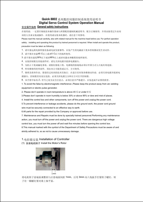
. To avoid the false by electromagnetic interference ,Please keep the product away from arc welding 1 equipment or electro pulse generator.2 . Please don’t operate in room temperature is above 45°C or under 0°C ·3 .Please don’t operate in room humidity is below 30% or above 95% or dew and mist of places.4 . Install the control box and other components, turn off the power and unplug the power cord.5 .To prevent interference or leakage accidents, please do the ground work, the power cord ground wire must be securely connected to an effective way to earth.6 .All parts for the repair provided by the Company or approved before use.7 . Maintenance and Repairs must be done by specially trained personnel.Performing any maintenance action, you must turn off the power and unplug the power cord. There are dangerous high voltage control box, you must turn the power off and wait five minutes before opening the control box. 8 .This manual marked with the symbol of the Department of Safety Precautions must be aware of and strictly adhered to, so as not to cause unnecessary damage.1. 电控箱安装 Installation of Controller(1) 安装电机转子 Install the Motor’s Rotor将电机转子前端面调整到与后套端面间距1mm ,后用3mm 内六角扳手拧紧转子螺钉,转 子有一颗螺钉要对准上轴平面。
交流伺服电机驱动器使用说明书.

交流伺服电机驱动器使用说明书1 •特点16位CPU+32位DSP三环(位置、速度、电流)全数字化控制脉冲序列、速度、转矩多种指令及其组合控制转速、转矩实时动态显示完善的自诊断保护功能,免维护型产品交流同步全封闭伺服电机适应各种恶劣环境体积小、重量轻2 •指标输入电源三相200V -10%〜+15% 50/60HZ控制方法IGBT PWM(正弦波)反馈增量式编码器(2500P/r )控制输入伺服-ON报警清除CW、CCW驱动、静止指令输入输入电压土10V控制电源DC12〜24V 最大200mA保护功能OU LU OS OL OH REG OC ST CPU 错误,DSP错误,系统错误通讯RS232C频率特性200Hz或更高(Jm=Jc时)体积L250 X W85 X H205 重量3.8Kg 3•原理见米纳斯驱动器方框图(图1)和控制方框图(图2)4•接线4.1主回路卸下盖板坚固螺丝;取下端子盖板。
用足够线经和连接器尺寸作连接,导线应采用额定温度600C以上的铜体线,装上端子盖板,拧紧盖板螺丝。
螺丝拧紧力矩大于1.2Nm M4或2.0 Nm M5时才可能损坏端子,接地线径为2.0mn i 具体见接线图34.2CN SIG 连接器[具体见接线图4驱动器和电机之间的电缆长度最大20M这些线至少要离开主电路接线30cm,不要让这些线与电源进线走一线槽;或让它们捆扎在一起线经0.18mm2或以上屏蔽双绞线,有足够的耐弯曲力屏蔽驱动器侧的屏蔽应连接到CN.SIG连接器的20脚,电机侧应连接到J 脚若电缆长于10M,则编码器电源线+5V、0V应接双线4.3CN I/F 连接控制器等周边设备与驱动器之间距离最大为3M这些线至少和主电路接线相隔30cm ,不要让这些线与电源进线走同一线槽或和它们捆扎在一起COM和COM之间的控制电源(V DC)由用户供给控制信号输出端子可以接受最大24V或50mA不要施加超过此限位的电压和电流若用控制信号直接使继电器动作要象左图所示那样,并联一只二极管到继电器。
迈信伺服驱动说明书

橙
与编码器W相输出连接,
W- 11
橙白
省线式请勿连接。
屏蔽线保护地 FG 15
裸线
裸线 与信号电缆屏蔽线连接。
注1:本公司提供成品16芯电缆,型号16FMB15。
注2:本公司提供成品10芯电缆,型号10FBM15X(机座号80电机使用),型号10FBM15(机座
号110及以上电机使用)。
14
2.4 标准接线图
EP1 交流伺服驱动器简明手册
12345 -1234 1.2.3.4.5.
12345,正数。
-1234,4位以内的负数, 前面显示减号表示负数。
-12345,5位负数,所有 小数点点亮表示负数。
3.2 主菜单
第 1 层是主菜单,共有 4 种操作方式,用 8、2 键改变方式,按 5 键进入第 2 层, 执行具体操作,按 4 键从第 2 层退回主菜单。
在同一配线管内。 请安装非熔断型断路器使驱动器故障时能及时切断外部电源。
2.1.3 电线规格
连接端子
符号
电线规格
主电路电源
L1、L2、L3
1.5~2.5mm2
控制电源
L1C、L2C
0.75~1.0mm2
电机连接端子
U、V、W
1.5~2.5mm2
接地端子
1.5~2.5mm2
控制信号端子
X1
≥0.14mm2(AWG26),含屏蔽线
EP1 交流伺服驱动器简明手册
2.4.1 位置控制接线图
15
EP1 交流伺服驱动器简明手册
第 3 章 面板操作
3.1 驱动器面板说明
3.1.1 面板组成
面板由 5 个 LED 数码管显示器和 4 个按键 8、2、4、5 组成,用来显示系统各
- 1、下载文档前请自行甄别文档内容的完整性,平台不提供额外的编辑、内容补充、找答案等附加服务。
- 2、"仅部分预览"的文档,不可在线预览部分如存在完整性等问题,可反馈申请退款(可完整预览的文档不适用该条件!)。
- 3、如文档侵犯您的权益,请联系客服反馈,我们会尽快为您处理(人工客服工作时间:9:00-18:30)。
海迈克伺服驱动器说明书
海迈克伺服驱动器是一种先进的电子设备,广泛应用于工业生产过程中的精密
定位和速度控制。
本说明书将详细介绍海迈克伺服驱动器的特点、原理和使用方法,以帮助用户更好地了解和使用该设备。
一、特点
1.1 高精度控制:海迈克伺服驱动器采用先进的数字控制技术,可实现对驱动
电机的高精度位置和速度控制,确保生产过程的稳定和准确。
1.2 多种控制模式:海迈克伺服驱动器支持多种控制模式,包括位置控制、速
度控制和力/扭矩控制,可根据用户需求自由切换,并根据实际工作情况进行参数
调整。
1.3 超高响应速度:海迈克伺服驱动器具备快速响应的特点,可以快速调整电
机转速和位置,以满足生产中的快速启停和精密定位的需求。
1.4 广泛适用性:海迈克伺服驱动器适用于各种类型的电机,包括直流电机、
步进电机和交流伺服电机等,能够满足不同行业的工业生产需求。
二、原理
海迈克伺服驱动器的工作原理基于闭环反馈控制系统。
当用户通过控制器发送
控制信号时,驱动器会通过内部的编码器获得电机的实时位置信息,并与目标位置进行比较。
根据差异值,驱动器将自动调整电机的转速和位置,使其尽可能接近目标位置。
伺服驱动器内部的控制算法会根据电机的速度和加速度参数以及用户设置的控
制模式,计算出合适的控制信号,并通过PWM(脉宽调制)技术将其转换为电机
驱动信号。
通过反馈电路的持续监测和反馈调整,驱动器能够实时跟踪和调整电机的运动状态,从而实现精确的位置和速度控制。
三、使用方法
3.1 连接电源:将伺服驱动器的电源线正确接入电源插座,并确保电源电压与设备规格相符。
3.2 连接电机:将电机的输出轴与伺服驱动器的输入轴正确连接,并确保连接牢固可靠。
3.3 参数设置:根据实际需求,通过伺服驱动器面板上的参数菜单,进行相应参数的设置。
这些参数包括电机类型、速度范围、加速度、减速度等。
注意:在进行参数设置时,请仔细阅读说明书,并按照操作步骤进行。
3.4 控制信号输入:通过控制器发送相应的控制信号,通常包括位置指令、速度指令和力/扭矩指令等。
3.5 启动和运行:按下启动按钮,伺服驱动器将根据用户设置的参数和控制信号,启动电机并控制其运动。
通过监测反馈信号,驱动器会实时调整电机的转速和位置,以满足预定的控制要求。
四、注意事项
4.1 在安装和使用伺服驱动器时,请务必遵循说明书中的操作步骤,确保正确连接和参数设置,以免产生故障或损坏设备。
4.2 在使用伺服驱动器过程中,应定期检查电机和驱动器的连接是否牢固,并保持设备的清洁和干燥状态,以确保长期稳定的运行。
4.3 在调整和更换伺服驱动器的参数时,请务必注意安全,确保电源已断开,并避免触碰到电器元件,以防触电或其他危险。
4.4 如果发现伺服驱动器运行异常或出现故障,请及时断开电源,并联系专业技术人员进行维修或更换。
综上所述,海迈克伺服驱动器是一种先进的电子设备,具备高精度控制、多种控制模式和快速响应等特点。
通过对驱动器的正确连接和参数设置,以及合理使用和维护,用户可以实现精密定位和速度控制的要求,提高生产效率和产品质量。