keithley2400数字源表说明书
KEITHLEY2400源表测试软件手册

KEITHLEY2400源表测试软件⼿册KEITHLEY(吉时利)2400系列源表测试软件中⽂说明书(Ver 201710)1⽬录第⼀章运⾏系统要求 (6)⼀、⽀持机型 (6)⼆、计算机要求 (6)第⼆章软件安装及设置 (7)⼀、通讯接⼝ (7)1.接⼝类型 (7)2.接⼝设置 (7)3.软件的安装 (7)⼆、系统参数设置 (8)第三章编辑测试项⽬ (10)⼀、什么是测试项⽬ (10)1.测试项⽬的定义 (10)2.为什么要使⽤测试项⽬ (10)⼆、建⽴⼀个测试项⽬ (10)三、测试项⽬的编辑 (12)1.修改步骤参数 (12)2.删除步骤参数 (13)3.调整步骤顺序 (13)四、测试项⽬的保存 (13)第四章功能设置 (14)⼀、通⽤设置 (14)22.接线⽅式(2、4线制) (15)3.测量速度 (16)4.⾃动调零 (16)5.滤波 (16)⼆、单阶恒流输出测量(BiasIMeasureV-Single) (16)1.功能简述 (16)2.参数设置 (16)三、单阶恒压输出测量(BiasVMeasureI-Single) (19)1.功能简述 (19)2.参数设置 (19)四、电流表测量模式(I-METER) (22)3.功能简述 (22)4.参数设置 (22)五、电压表测量模式(V-METER) (23)1.功能简述 (23)2.参数设置 (23)六、电阻测量(Resistance) (25)1.功能简述 (25)2.参数设置 (25)七、多阶恒流输出测量(BiasIMeasureV-Steps) (26)1.功能简述 (26)2.参数设置 (26)⼋、多阶恒压输出测量(BiasVMeasureI-Steps) (28) 32.参数设置 (29)九、电流扫描测量(SweepIMeasureV) (30)1.功能简述 (30)2.参数设置 (31)3.测试数据图形 (32)⼗、电压扫描测量(SweepVMeasureI) (33)1.功能简述 (33)2.参数设置 (33)3.测试数据图形 (35)⼗⼀、太阳能电池IV特性测量(SolarCell-IV) (35)1.功能简述 (35)2.参数设置 (35)3.数据的格式 (37)第五章运⾏测量 (38)⼀、开始及终⽌运⾏ (38)⼆、数据及图形的保存格式 (38)第六章常见应⽤测试 (39)⼀、⼆线制与四线制的选择 (39)⼆、使⽤⾃动量程还是固定量程 (40)三、同时测试两个样品 (40)四、⽤多阶恒压/流进⾏⽅波及阶梯波测量 (41)五、任意定制I-V扫描 (42)4六、⼆极管IV特性测量测量 (43)七、电化学应⽤ (44)5第⼀章运⾏系统要求⼀、⽀持机型KEITHLEY2400,2401,2410,2420,2430,2440;如⽤户需要对KEITHLEY2450图形源表系列进⾏控制,请联系我们,我们将提供另外⼀款专门针对2450系列(2450,2460,2461)软件产品供您使⽤。
Tektronix Keithley Series 2400 Source Measure Unit

S M U I N S T R U M E N T S by eliminating many of the complex synchronization and connection issues associated with using multiple instruments. And, their compact half-rack size conserves precious “real estate” in the test rack or bench.Power of Five Instruments in One (IV Source, IVR Measure)The tightly coupled nature of a SourceMeter SMU instrument provides many advantages over solu-tions configured from separate instruments, such as a precision power supply and a digital multime-ter. For example, it provides faster test times by reducing GPIB traffic and simplifies the remote pro-gramming interface. It also protects the device under test from damage due to accidental overloads, thermal runaway, etc. Both the current and voltage source are programmable with readback to help maximize device measurement integrity. If the readback reaches a programmed compliance limit, then the source is clamped at the limit, providing fault protection.• Five instruments in one (IV Source, IVR Measure)• Seven models: 20–100W DC, 1000W pulsed, 1100V to 1µV, 10A to 10pA • Source and sink (4-quadrant) operation • 0.012% basic measure accuracy with 6½-digit resolution • 2-, 4-, and 6-wire remoteV-source and measure sensing • 1700 readings/second at 4½ digits via GPIB • Pass/Fail comparator for fast sorting/binning • Available high speed sense lead contact check function • Programmable DIO port for automation/handler/prober control (except Model 2401)• Standard SCPI GPIB, RS-232 and Keithley Trigger Link interfaces • Keithley LabTracer 2.0 I-V curve tracing application software (download)TEST LEADS AND PROBES 1754 2-Wire Universal 10-Piece Test Lead Kit 5804 Kelvin (4-Wire) Universal 10-Piece Test Lead Kit 5805 Kelvin (4-Wire) Spring-Loaded Probes 5808 Low Cost Single-pin Kelvin Probe Set 5809 Low Cost Kelvin Clip Lead Set 8607 2-Wire, 1000V Banana Cables, 1m (3.3 ft)CA-18-1 Shielded Dual Banana Cable, 1.2m (4 ft)SWITCHING HARDWARE 7001 Two-Slot Switch System 7002 Ten-Slot Switch System 7019-C 6-Wire Ohms Switch Card 7053 High-Current Switch Card CABLES/ADAPTERS 7007-1 Shielded GPIB Cable, 1m (3.3 ft)7007-2 Shielded GPIB Cable, 2m (6.6 ft)7009-5 RS-232 Cable 8620 Shorting PlugT i g h t l y c o u p l e d p r e c i s i o n s o u r c i n g a n d m e a s u r e m e n tSource I–Measure V, I, or W configurationSource V–Measure I, V, or W configurationI-V CharacteristicsAll SourceMeter SMU instruments provide four-quadrant operation. In the first and third quadrants they o perate as a source, delivering power to a load. In the second and fourth quadrants they oper-ate as a sink, d issipating power internally. Voltage, current, and resistance can be measured during source or sink o peration.SourceMeter ®SMU InstrumentsS M U I N S T R U M E N T SAutomation for SpeedA SourceMeter SMU instrument streamlines production testing. It sources voltage or current while making measurements without needing to change connections. It is designed for reliable operation in non-stop production environments. To provide the throughput demanded by production applica-tions, the SourceMeter SMU instrument offers many built-in features that allow it to run complex test sequences without computer control or GPIB communications slowing things down.Standard and Custom SweepsSweep solutions greatly accelerate testing with automation hooks. Three basic sweep waveforms are provided that can be programmed for sin-gle-event or continuous operation. They are ideal for I/V, I/R, V/I, and V/R characterization.• Linear Staircase Sweep: Moves from the start level to the stop level in equal linear steps • Logarithmic Staircase Sweep: Done on a log scale with a specified number of steps per decade• Custom Sweep: Allows construction of special sweeps by specifying the number of measurement points and the source level at each point• Up to 1700 readings/second at 4½ digits to the GPIB bus• 5000 readings can be stored in the non-volatile buffer memoryBuilt-In Test Sequencer(Source Memory List)The Source Memory list provides faster and eas-ier testing by allowing you to setup and execute up to 100 different tests that run without PC intervention.• Stores up to 100 instrument configurations, each containing source settings, measurements ettings, pass/fail criteria, etc.• Pass/fail limit test as fast as 500µs per point• Onboard comparator eliminates the delay caused when sending data to the computer for analysis •Built-in, user definable math functions to calculate derived parametersTYPICAL APPLICATIONSDevices:• Discrete semiconductor devices • Passive devices• Transient suppression devices • ICs, RFICs, MMICs• Laser diodes, laser diodemodules, LEDs, photodetectors • Circuit protection devices: TVS, MOV, Fuses, etc.• Airbags• Connectors, switches, relays • High brightness LEDs (DC and pulse)Tests:• Leakage• Low voltage/resistances • LIV • IDDQ• I-V characterization• Isolation and trace resistance • Temperature coefficient • Forward voltage, reverse breakdown, leakage current • DC parametric test • DC power source • HIPOT• Photovoltaic cell efficiency (source and sink)•Dielectric withstandingT i g h t l y c o u p l e d p r e c i s i o n s o u r c i n g a n d m e a s u r eDigital I/O InterfaceThe digital I/O interface can link a SourceMeter SMU instrument to many popular component handlers, including Aetrium, Aeco, and Robotronics. Other capabilities of the interface include:• Tight systems integration for applications such as binning and sorting • Built-in component handler interface• Start of test and end of test signals• 5V, 300mA power supply• Optional expander accessory (Model 2499-DIGIO) adds 16 digital I/O lines The digital I/O interface is available on all Series 2400 SoourceMeter instruments except the Model 2401.Trigger Link InterfaceAll SourceMeter SMU instruments include Keithley’s unique Trigger Link interface which provides high-speed, seamless communications with many of Keithley’s other instruments. For example, use the Trigger Link interface to connect a SourceMeter SMU instrument with a Series 7000 Switching System for a complete multi-point test solution. With Trigger Link, the Series 7000 Switching Systems can be controlled by a SourceMeter SMU instrument during a high-speed test sequence independent of a computer and GPIB.Optional Contact Check FunctionThe Contact Check function makes it simple to verify good connections quickly and easily before an automated test sequence begins. This elimi-nates measurement errors and false product failures associated with con-tact fatigue, breakage, contamination, loose or broken connection, relay failures, etc. Some capabilities of this function are:• 350µs verification and notification process time• The output of the SourceMeter SMU instrument is automatically shut off after a fault and is not re-activated until good contact is verified, protecting the device under test from damage and the operator from potential safety h azards.• 3 pass/fail threshold values: 2W, 15W, and 50W• No energy passes through the device under test during the operation.• Enabled either from the front panel or remotely over the GPIB• 3 fault notification methods Unique 6-Wire Ohms TechniqueSourceMeter SMU instruments can make standard 4-wire, split Kelvin, and 6-wire, guarded ohms measurements and can be configured for either the constant current or constant voltage method. The 6-wire ohms technique:• Uses guard and guard sense leads in addition to the 4-wire sense and source leads.• Locks out parallel current paths when measuring resistor networks or hybrid c ircuits to isolate the component under test.• Allows users to configure and plot data easily from Series 2400 SourceMeter SMU instruments, making characterization of two, three, and four terminal devices a snap.Contact check option for 4-wire or 6-wire applications Free LabTracer 2.0 device characterization software (downloadable)6-Wire Ohms Circuit. All test current flows through R1 because thehigh current guard drives the voltage across R2 to 0V.S M U I N S T R U M E N T STEMPERATURE COEFFICIENT (0°–18°C and 28°–50°C): ±(0.15 × accuracy specification)/°C.VOLTAGE REGULATION: Line: 0.01% of range. Load: 0.01% of range + 100µV.OVER VOLTAGE PROTECTION: User selectable values, 5% tolerance. Factory default = none.CURRENT LIMIT: Bipolar current limit (compliance) set with single value. Min. 0.1% of range.OVERSHOOT: <0.1% typical (full scale step, resistive load, 10mA range).ADDITIONAL SOURCE SPECIFICATIONS (All Models)TRANSIENT RESPONSE TIME: 30µs minimum for the output to recover to its spec. following a step change in load.COMMAND PROCESSING TIME: Maximum time required for the output to begin to change following the receipt of :SOURce:VOLTage|CURRent <nrf> command. Autorange On: 10ms. Autorange Off: 7ms.OUTPUT SETTLING TIME: Time required to reach 0.1% of final value after command is pro-cessed. 100µs typical. Resistive load. 10µA to 100mA range.DC FLOATING VOLTAGE: Output can be floated up to ±250VDC (Model 2440 ±40VDC) from chassis ground.REMOTE SENSE: Up to 1V drop per load lead.COMPLIANCE ACCURACY: Add 0.3% of range and ±0.02% of reading to base specification.OVER TEMPERATURE PROTECTION: Internally sensed temperature overload puts unit in stand-by mode.RANGE CHANGE OVERSHOOT: Overshoot into a fully resistive 100k W load, 10Hz to 1MHz BW, adjacent ranges: 100mV typical, except 20V/200V (20V/60V on Model 2420), 20V/100V on Model 2425 and 2430, range boundary, and Model 2440.MINIMUM COMPLIANCE VALUE: 0.1% of range.ADDITIONAL PULSE MODE SOURCE SPECIFICATIONS (2430 and 2430-C only)MAXIMUM DUTY CYCLE: 8%, hardware limited, 10A range only. All other ranges 100%.MAXIMUM PULSE WIDTH: 5ms from 90% rising to 90% falling edge, 2.5ms 10A range.MINIMUM PULSE WIDTH: 150µs.MINIMUM PULSE RESOLUTION: 50µs typical, 70µs max., limited by system j itter.SOURCE ACCURACY: Determined by settling time and source range specifications.OUTPUT SETTLING TIME 0.1%:800µs typ., source I = 10A into 10W , limited by voltage slew rate. 500µs typ., source I = 10A into 1W , limited by voltage slew rate.OUTPUT SLEW RATE:Voltage (10W load): 0.25V/µs ±30% on 100V range. 0.08V/µs ±30% on 20V range, 10A range. Current (0W load): 0.25A/µs ±30% on 100V range. 0.08A/µs ±30% on 20V range, 10A range.NOTES1. 2400, 2401, 2410 Only: Specifications valid for continuous output currents below 105mA. For operation above 105mA continuous for >1 minute, derate accuracy 10%/35mA above 105mA.2. Speed = Normal (1 PLC). For 0.1 PLC, add 0.005% of range to offset specifications, except 200mV, 1A, 10Aranges, add 0.05%. For 0.01 PLC, add 0.05% of range to offset specifications, except 200mV, 1A, 10A ranges, add 0.5%.3. Accuracies apply to 2- or 4-wire mode when properly zeroed.4. In pulse mode, limited to 0.1 PLC measurement.S e r i e s 2400 c o n d e n s e d s p e c i f i c a t i o n sTEMPERATURE COEFFICIENT (0°–18°C and 28°–50°C): ±(0.15 × accuracy specification)/°C.CURRENT REGULATION: Line: 0.01% of range. Load: 0.01% of range (except Model 2440 5A range 0.05%) + 100pA.VOLTAGE LIMIT: Bipolar voltage limit (compliance) set with single value. Min. 0.1% of range.OVERSHOOT: <0.1% typical (1mA step, RL = 10k W , 20V range for Model 2400, 2401, 2410, 2420, 2425, 2430), (10V range for Model 2440).CONTACT CHECK SPECIFICATIONS (requires -C version)(Not available for Model 2401)SPEED: 350µs for verification and notification.CONTACT CHECK: 2 W 15 W 50 W No contact check failure <1.00 W <13.5 W <47.5 W Always contact check failure >3.00 W >16.5 W >52.5 WNOTES1. 2400, 2401, 2410 Only: Specifications valid for continuous output currents below 105mA. For operation above 105mA continuous for >1 minute, derate accuracy 10%/35mA above 105mA.2. Full operation (1A) regardless of load to 30°C (50°C for Model 2420 and 2440). Above 30°C (50°C for Model 2420 and 2440) ambient, derate 35mA/°C and prorate 35mA/W load. 4-wire mode. For current sink operation on 1A, 3A, or 5A ranges, maximum continuous power is limited to approximately 1/2 rated power or less, depending on current, up to 30°C ambient. See power equations in the User’s Manual to calculate allowable duty cycle for specific conditions.3. For sink mode, 1µA to 100mA range, accuracy is:Model 2400, 2401: ±(0.15% + offset*4). Models 2410, 2420, 2425, 2430, 2440: ±(0.5% + offset*3). For 1A range, accuracy is:Model 2400, 2401: ±(1.5% + offset*8). Models 2410, 2420, 2425, 2430, 2440: ±(1.5% + offset*3).4. 10A range only in pulse mode. Limited to 2.5ms pulse width maximum. 10% duty cycle maximum.5. Speed = Normal (1 PLC). For 0.1 PLC, add 0.005% of range to offset specifications, except 200mV, 1A, 10A ranges, add 0.05%. For 0.01 PLC, add 0.05% of range to offset specifications, except 200mV, 1A, 10A ranges, add 0.5%.6. Accuracies apply to 2- or 4-wire mode when properly zeroed.7. In pulse mode, limited to 0.1 PLC measurement.8. Model 2400 and 2400-C only.2400S M U I N S T R U M E N T S NOTES1. Speed = Normal (1 PLC). For 0.1 PLC, add 0.005% of range to offset specifications, except 200mV, 1A, 10A ranges, add 0.05%. For 0.01 PLC, add 0.05% of range to offset specifications, except 200mV, 1A, 10A ranges, add 0.5%.2. Accuracies apply to 2- or 4-wire mode when properly zeroed.3. Manual ohms only – except 2420, 2425, 2430, 2440 for 2W range and 2400, 2401, or 2410 for 200M W range.4. Source readback enabled, offset compensation ON. Also available on 2410, 2420, 2425, 2430, and 2440 with similar a ccuracy enhancement.5. In pulse mode, limited to 0.1 PLC measurement.6. Except 2440; default test current is 5µA.7. Except 2440; default test current is 0.5µA.TEMPERATURE COEFFICIENT (0°–18°C and 28°–50°C): ±(0.15 × accuracy spec-ification)/°C.SOURCE I MODE, MANUAL OHMS: Total uncertainty = I source accuracy + V meas-ure accuracy (4-wire remote sense).SOURCE V MODE, MANUAL OHMS: Total uncertainty = V source a ccuracy + I meas-ure accuracy (4-wire remote sense).6-WIRE OHMS MODE: Available using active ohms guard and guard sense. Max. Guard Output Current: 50mA (except 1A range). Accuracy is load dependent. Refer to White Paper no. 2033 for calculation f ormula.GUARD OUTPUT IMPEDANCE: <0.1W in ohms mode.SERVICES AVAILABLE2400-3Y-EW 1-year factory warranty extended to 3 years from date of shipment 2400-C-3Y-EW 1-year factory warranty extended to 3 years from date of shipment 2401-3Y-EW 1-year factory warranty extended to 3 years from date of shipment 2410-3Y-EW 1-year factory warranty extended to 3 years from date of shipment 2410-C-3Y-EW 1-year factory warranty extended to 3 years from date of shipment 2420-3Y-EW 1-year factory warranty extended to 3 years from date of shipment 2420-C-3Y-EW 1-year factory warranty extended to 3 years from date of shipment 2425-3Y-EW 1-year factory warranty extended to 3 years from date of shipment 2425-C-3Y-EW 1-year factory warranty extended to 3 years from date of shipment 2430-3Y-EW 1-year factory warranty extended to 3 years from date of shipment 2430-C-3Y-EW 1-year factory warranty extended to 3 years from date of shipment 2440-3Y-EW 1-year factory warranty extended to 3 years from date of shipment 2440-C-3Y-EW 1-year factory warranty extended to 3 years from date of shipmentC/2400-3Y-ISO 3 (ISO-17025 accredited) calibrations within 3 years of purchase for Models 2400, 2400-C, 2400-LV*C/2401-3Y-ISO 3 (ISO-17025 accredited) calibrations within 3 years of purchase for Model 2401*C/2410-3Y-ISO 3 (ISO-17025 accredited) calibrations within 3 years of purchase for Models 2410, 2410-C*C/2420-3Y-ISO 3 (ISO-17025 accredited) calibrations within 3 years of purchase for Models 2420, 2420-C*C/2425-3Y-ISO 3 (ISO-17025 accredited) calibrations within 3 years of purchase for Models 2425, 2425-C*C/2430-3Y-ISO 3 (ISO-17025 accredited) calibrations within 3 years of purchase for Models 2430, 2430-C*C/2440-3Y-ISO 3 (ISO-17025 accredited) calibrations within 3 years of purchase for Models 2440, 2440-C*TRN-2400-1-C Course: Unleashing the Power of Your SourceMeter SMU Instrument*Not available in all countriesS e r i e s 2400 c o n d e n s e d s p e c i f i c a t i o n sSystem SpeedsMEASUREMENT 1MAXIMUM RANGE CHANGE RATE: 75/second.MAXIMUM MEASURE AUTORANGE TIME: 40ms (fixed source).2Sweep Operation 3 Reading Rates (rdg./second) for 60Hz (50Hz):MeasureSource-MeasureSource-Measure 5Pass/Fail Test 4, 5Source-Memory 4Speed NPLC/Trigger OriginTo Mem.To GPIB To Mem.To GPIB To Mem.To GPIB To Mem.To GPIB Fast0.01 / internal 2081(2030)17541551(1515)1369902(900)981165(162)165Single Reading Operation Reading Rates (rdg./second) for 60Hz (50Hz):SpeedNPLC/Trigger OriginMeasure To GPIB Source-Measure 5To GPIB Source-Measure Pass/Fail Test 4,5To GPIB Fast (488.1)0.01 / internal 537140135Component for 60Hz (50Hz):4, 6Speed NPLC/Trigger OriginMeasure To GPIB Source Pass/Fail TestSource-Measure Pass/Fail Test 5, 7To GPIB Fast 0.01 / external 1.04 ms (1.08 ms)0.5 ms (0.5 ms) 4.82 ms (5.3 ms)Medium 0.10 / external 2.55 ms (2.9 ms)0.5 ms (0.5 ms) 6.27 ms (7.1 ms)Normal 1.00 / external 17.53 ms (20.9 ms)0.5 ms (0.5 ms)21.31 ms (25.0 ms)1Reading rates applicable for voltage or current measurements. Auto zero off, autorange off, filter off, display off, trigger delay = 0, and binary reading format.2 Purely resistive lead. 1µA and 10µA ranges <65ms.3 1000 point sweep was characterized with the source on a fixed range.4 Pass/Fail test performed using one high limit and one low math limit.5Includes time to re-program source to a new level before making m easurement.6 Time from falling edge of START OF TEST signal to falling edge of END OF TEST signal.7 Command processing time of :SOURce:VOLTage|CURRent:TRIGgered <nrf> command not included.NOTES2400Contact Information:Australia* 1 800 709 465Austria 00800 2255 4835Balkans, Israel, South Africa and other ISE Countries +41 52 675 3777Belgium* 00800 2255 4835Brazil +55 (11) 3759 7627Canada 180****9200Central East Europe / Baltics +41 52 675 3777Central Europe / Greece +41 52 675 3777Denmark +45 80 88 1401Finland +41 52 675 3777France* 00800 2255 4835Germany* 00800 2255 4835Hong Kong 400 820 5835India 000 800 650 1835Indonesia 007 803 601 5249Italy 00800 2255 4835Japan 81 (3) 6714 3010Luxembourg +41 52 675 3777Malaysia 180****5835Mexico, Central/South America and Caribbean 52 (55) 56 04 50 90Middle East, Asia, and North Africa +41 52 675 3777The Netherlands* 00800 2255 4835New Zealand 0800 800 238Norway 800 16098People’s Republic of China 400 820 5835Philippines 1 800 1601 0077Poland +41 52 675 3777Portugal 80 08 12370Republic of Korea +82 2 6917 5000Russia / CIS +7 (495) 6647564Singapore 800 6011 473South Africa +41 52 675 3777Spain* 00800 2255 4835Sweden* 00800 2255 4835Switzerland* 00800 2255 4835Taiwan 886 (2) 2656 6688Thailand 1 800 011 931United Kingdom / Ireland* 00800 2255 4835USA 180****9200Vietnam 12060128* European toll-free number. If notaccessible, call: +41 52 675 3777Find more valuable resources at Copyright © Tektronix. All rights reserved. Tektronix products are covered by U.S. and foreign patents, issued and pending. Information in this publication supersedes thatin all previously published material. Specification and price change privileges reserved. TEKTRONIX and TEK are registered trademarks of Tektronix, Inc. All other trade namesreferenced are the service marks, trademarks or registered trademarks of their respective companies.04.12.16 1BW-60414-0。
美国吉时利keithley2400系列数字源表最新技术指标资料说明书

by eliminating many of the complex synchronization and connection issues associated with using multiple instruments . And, their compact half-rack size conserves precious “real estate” in the test rack or bench .Power of five Instruments in one (IV source, IVr Measure)The tightly coupled nature of a SourceMeter SMU instrument provides many advantages over solu-tions configured from separate instruments, such as a precision power supply and a digital multime-five instruments in one (IV source, IVr Measure)seven models: 20–100W DC,1000W pulsed, 1100V to 1µV,10a to 10pasource and sink (4-quadrant)S M U I N S T R U M E N T Ssource I–Measure V, I, or W configurationsource V–Measure I, V, or W configurationI-V CharacteristicsAll SourceMeter SMU instruments provide four-quadrant operation . In the first and third quadrantstheyo perate as a source, delivering power to a load . In the second and fourth quadrants they oper-ate as a sink,d issipating power internally . Voltage, current, and resistance can be measured during source or sink o peration .T i g h t l y c o u p l e d p r e c i s i o n s o u r c i n g a n d m e a s u r e m e n tautomation for speedA SourceMeter SMU instrument streamlines production testing . It sources voltage or current while making measurements without needing to change connections . It is designed for reliable operation in non-stop production environments . To provide the throughput demanded by production applica-tions, the SourceMeter SMU instrument offers many built-in features that allow it to run complex test sequences without computer control or GPIB communications slowing things down .standard and Custom sweepsSweep solutions greatly accelerate testing with automation hooks . Three basic sweep waveforms are provided that can be programmed for single-event or continuous operation . They are ideal for I/V, I/R, V/I, and V/R characterization .•Linear Staircase Sweep: Moves from the start level to the stop level in equal linear steps •Logarithmic Staircase Sweep: Done on a log scale with a specified number of steps per decade•Custom Sweep: Allows construction of special sweeps by specifying the number of measurement points and the source level at each point•Up to 1700 readings/second at 4½ digits to the GPIB bus•5000 readings can be stored in the non-volatile buffer memorybuilt-In Test sequencer(source Memory list)The Source Memory list provides faster andeasier testing by allowing you to setup andexecute up to 100 different tests that run without PC intervention .•Stores up to 100 instrument configurations, each containing source settings, measurements ettings, pass/fail criteria, etc .•Pass/fail limit test as fast as 500µs per point•Onboard comparator eliminates the delay caused when sending data to the computer for analysis •Built-in, user definable math functions to calculate derived parametersTYPICal aPPlICaTIoNsDevices:•Discrete semiconductor devices •Passive devices•Transient suppression devices •ICs, rfICs, MMICs•laser diodes, laser diodemodules, lEDs, photodetectors •Circuit protection devices: TVs,MoV, fuses, etc.•airbags•Connectors, switches, relays •High brightness lEDs (DC and pulse)Tests:•leakage•low voltage/resistances •lIV •IDDQ•I-V characterization•Isolation and trace resistance •Temperature coefficient •forward voltage, reverse breakdown, leakage current •DC parametric test •DC power source •HIPoT•Photovoltaic cell efficiency (source and sink)•Dielectric withstandingS M U I N S T R U M E N T SDigital I/o InterfaceThe digital I/O interface can link a SourceMeter SMU instrument to many popular component handlers, including Aetrium, Aeco, and Robotronics . Other capabilities of the interface include:•Tight systems integration for applications such as binning and sorting •Built-in component handler interface •Start of test and end of test signals •5V, 300mA power supply• Optional expander accessory (Model 2499-DIGIO) adds 16 digital I/O linesThe digital I/O interface is available on all Series 2400 SoourceMeter instruments except the Model 2401 .Trigger link InterfaceAll SourceMeter SMU instruments include Keithley’s unique Trigger Link interface which provides high-speed, seamless communications with many of Keithley’s other instruments . For example, use the Trigger Link interface to connect a SourceMeter SMU instrument with a Series 7000 Switching System for a complete multi-point test solution . With Trigger Link, the Series 7000 Switching Systems can be controlled by a SourceMeter SMU instrument during a high-speed test sequence independent of a computer and GPIB .optional Contact Check functionThe Contact Check function makes it simple to verify good connections quickly and easily before an automated test sequence begins . This elimi-nates measurement errors and false product failures associated with con-tact fatigue, breakage, contamination, loose or broken connection, relay failures, etc . Some capabilities of this function are:•350µs verification and notification process time•The output of the SourceMeter SMU instrument is automatically shut off after a fault and is not re-activated until good contact is verified,protecting the device under test from damage and the operator frompotential safetyh azards .•3 pass/fail threshold values: 2W , 15W , and 50W•No energy passes through the device under test during the operation .•Enabled either from the front panel or remotely over the GPIB •3 fault notification methodsunique 6-Wire ohms TechniqueSourceMeter SMU instruments can make standard 4-wire, split Kelvin, and 6-wire, guarded ohms measurements and can be configured for either the constant current or constant voltage method . The 6-wire ohms technique:•Uses guard and guard sense leads in addition to the 4-wire sense and source leads .•Locks out parallel current paths when measuring resistor networks or hybrid c ircuits to isolate the component under test .•Allows users to configure and plot data easily from Series 2400SourceMeter SMU instruments, making characterization of two, three,and four terminal devices a snap .Contact check option for 4-wire or 6-wire applications free labTracer 2.0 device characterization software (downloadable)6-Wire ohms Circuit. all test current flows through r1 because the high current guard drives the voltage across r2 to 0V.T i g h t l y c o u p l e d p r e c i s i o n s o u r c i nTEMPERATURE COEFFICIENT (0°–18°C and 28°–50°C): ±(0 .15 × accuracy specification)/°C .aDDITIoNal PulsE MoDE sourCE sPECIfICaTIoNs (2430 and 2430-C only)MAXIMUM DUTy CyCLE: 8%, hardware limited, 10A range only . All other ranges 100% .MAXIMUM PULSE WIDTH: 5ms from 90% rising to 90% falling edge, 2 .5ms 10A range .MINIMUM PULSE WIDTH: 150µs .MINIMUM PULSE RESOLUTION: 50µs typical, 70µs max ., limited by system j itter .SOURCE ACCURACy: Determined by settling time and source range specifications .OUTPUT SETTLING TIME 0.1%:800µs typ ., source I = 10A into 10W , limited by voltage slew rate . 500µs typ ., source I = 10A into 1W , limited by voltage slew rate .OUTPUT SLEW RATE:Voltage (10W load): 0 .25V/µs ±30% on 100V range . 0 .08V/µs ±30% on 20V range, 10A range . Current (0W load): 0 .25A/µs ±30% on 100V range . 0 .08A/µs ±30% on 20V range, 10A range .NoTEs1 . 2400, 2401, 2410 Only: Specifications valid for continuous output currents below 105mA . For operation above 105mA continuous for >1 minute, derate accuracy 10%/35mA above 105mA .2 . Speed = Normal (1 PLC) . For 0 .1 PLC, add 0 .005% of range to offset specifications, except 200mV, 1A, 10Aranges, add 0 .05% . For 0 .01 PLC, add 0 .05% of range to offset specifications, except 200mV, 1A, 10A ranges, add 0 .5% .3 . Accuracies apply to 2- or 4-wire mode when properly zeroed .4 . In pulse mode, limited to 0 .1 PLC measurement .2400S M U I N S T R U M E N T STEMPERATURE COEFFICIENT (0°–18°C and 28°–50°C): ±(0 .15 × accuracy specification)/°C .CURRENT REGULATION: Line: 0 .01% of range . Load: 0 .01% of range (except Model 2440 5A range 0 .05%) + 100pA .VOLTAGE LIMIT: Bipolar voltage limit (compliance) set with single value . Min . 0 .1% of range .OVERSHOOT: <0 .1% typical (1mA step, RL = 10k W , 20V range for Model 2400, 2401, 2410, 2420, 2425, 2430), (10V range for Model 2440) .CoNTaCT CHECK sPECIfICaTIoNs (requires -C version)(Not available for Model 2401)SPEED: 350µs for verification and notification .CONTACT CHECK: 2 W 15 W 50 W No contact check failure <1 .00 W <13 .5 W <47 .5 W Always contact check failure >3 .00 W >16 .5 W >52 .5 WNoTEs1 . 2400, 2401, 2410 Only: Specifications valid for continuous output currents below 105mA . For operation above 105mA continuous for >1 minute, derate accuracy 10%/35mA above 105mA .2 . Full operation (1A) regardless of load to 30°C (50°C for Model 2420 and 2440) . Above 30°C (50°C for Model 2420 and 2440) ambient, derate 35mA/°C and prorate 35mA/W load . 4-wire mode . For current sink operation on 1A, 3A, or 5A ranges, maximum continuous power is limited to approximately 1/2 rated power or less, depending on current, up to 30°C ambient . See power equations in the User’s Manual to calculate allowable duty cycle for specific conditions .3 . For sink mode, 1µA to 100mA range, accuracy is:Model 2400, 2401: ±(0 .15% + offset*4) . Models 2410, 2420, 2425, 2430, 2440: ±(0 .5% + offset*3) .For 1A range, accuracy is:Model 2400, 2401: ±(1 .5% + offset*8) . Models 2410, 2420, 2425, 2430, 2440: ±(1 .5% + offset*3) .4 . 10A range only in pulse mode . Limited to 2 .5ms pulse width maximum . 10% duty cycle maximum .5 . Speed = Normal (1 PLC) . For 0 .1 PLC, add 0 .005% of range to offset specifications, except 200mV, 1A, 10A ranges, add 0 .05% . For 0 .01 PLC, add 0 .05% of range to offset specifications, except 200mV, 1A, 10A ranges, add 0 .5% .6 . Accuracies apply to 2- or 4-wire mode when properly zeroed .7 . In pulse mode, limited to 0 .1 PLC measurement .8 . Model 2400 and 2400-C only .S e r i e s 2400 c o n d e n s e d s p e c i f i c a t i o n sNoTEs1 . Speed = Normal (1 PLC) . For 0 .1 PLC, add 0 .005% of range to offset specifications, except 200mV, 1A, 10A ranges, add 0 .05% . For 0 .01 PLC, add 0 .05% of range to offset specifications, except 200mV, 1A, 10A ranges, add 0 .5% .2 . Accuracies apply to 2- or 4-wire mode when properly zeroed .3 . Manual ohms only – except 2420, 2425, 2430, 2440 for 2W range and 2400, 2401, or 2410 for 200M W range .4 . Source readback enabled, offset compensation ON . Also available on 2410, 2420, 2425, 2430, and 2440 with similar a ccuracy enhancement .5 . In pulse mode, limited to 0 .1 PLC measurement .6 . Except 2440; default test current is 5µA .7 . Except 2440; default test current is 0 .5µA .TEMPERATURE COEFFICIENT (0°–18°C and 28°–50°C): ±(0 .15 × accuracy specification)/°C .SOURCE I MODE, MANUAL OHMS: Total uncertainty = I source accuracy + V meas-ure accuracy (4-wire remote sense) .SOURCE V MODE, MANUAL OHMS: Total uncertainty = V source a ccuracy + I meas-ure accuracy (4-wire remote sense) .6-WIRE OHMS MODE: Available using active ohms guard and guard sense . Max . Guard Output Current: 50mA (except 1A range) . Accuracy is load dependent . Refer to White Paper no . 2033 for calculation f ormula .GUARD OUTPUT IMPEDANCE: <0 .1W in ohms mode .sErVICEs aVaIlablE2400-3Y-EW 1-year factory warranty extended to 3 years from date of shipment 2400-C-3Y-EW 1-year factory warranty extended to 3 years from date of shipment2401-3Y-EW1-year factory warranty extended to 3 years from date of shipment 2410-3Y-EW 1-year factory warranty extended to 3 years from date of shipment 2410-C-3Y-EW 1-year factory warranty extended to 3 years from date of shipment2420-3Y-EW1-year factory warranty extended to 3 years from date of shipment 2420-C-3Y-EW 1-year factory warranty extended to 3 years from date of shipment 2425-3Y-EW 1-year factory warranty extended to 3 years from date of shipment 2425-C-3Y-EW 1-year factory warranty extended to 3 years from date of shipment 2430-3Y-EW 1-year factory warranty extended to 3 years from date of shipment 2430-C-3Y-EW 1-year factory warranty extended to 3 years from date of shipment2440-3Y-EW1-year factory warranty extended to 3 years from date of shipment 2440-C-3Y-EW 1-year factory warranty extended to 3 years from date of shipmentC/2400-3Y-ISO 3 (ISO-17025 accredited) calibrations within 3 years of purchase for Models 2400, 2400-C, 2400-LV*C/2401-3Y-ISO 3 (ISO-17025 accredited) calibrations within 3 years of purchase for Model 2401*C/2410-3Y-ISO 3 (ISO-17025 accredited) calibrations within 3 years of purchase for Models 2410, 2410-C*C/2420-3Y-ISO 3 (ISO-17025 accredited) calibrations within 3 years of purchase for Models 2420, 2420-C*C/2425-3Y-ISO 3 (ISO-17025 accredited) calibrations within 3 years of purchase for Models 2425, 2425-C*C/2430-3Y-ISO 3 (ISO-17025 accredited) calibrations within 3 years of purchase for Models 2430, 2430-C*C/2440-3Y-ISO 3 (ISO-17025 accredited) calibrations within 3 years of purchase for Models 2440, 2440-C*TRN-2400-1-C Course: Unleashing the Power of Your SourceMeter SMU Instrument *Not available in all countries2400S M U I N S T R U M E N T Ssystem speedsMEasurEMENT 1MAXIMUM RANGE CHANGE RATE: 75/second .MAXIMUM MEASURE AUTORANGE TIME: 40ms (fixed source) .2sweep operation 3 reading rates (rdg./second) for 60Hz (50Hz):Measuresource-Measuresource-Measure 5Pass/fail Test 4, 5source-Memory 4speed NPlC/Trigger originTo Mem.To GPIb To Mem.To GPIb To Mem.To GPIb To Mem.To GPIb Fast0 .01 / internal 2081(2030)17541551(1515)1369902(900)981165(162)165single reading operation reading rates (rdg./second) for 60Hz (50Hz):speedNPlC/Trigger originMeasure To GPIb source-Measure 5To GPIb source-Measure Pass/fail Test 4,5To GPIb Fast (488.1)0 .01 / internal 537140135Component for 60Hz (50Hz):4, 6speed NPlC/Trigger originMeasure To GPIb source Pass/fail Testsource-Measure Pass/fail Test 5, 7To GPIb Fast 0 .01 / external 1 .04 ms (1 .08 ms)0 .5 ms (0 .5 ms) 4 .82 ms (5 .3 ms)Medium 0 .10 / external 2 .55 ms (2 .9 ms)0 .5 ms (0 .5 ms) 6 .27 ms (7 .1 ms)Normal 1 .00 / external 17 .53 ms (20 .9 ms)0 .5 ms (0 .5 ms)21 .31 ms (25 .0 ms)1Reading rates applicable for voltage or current measurements . Auto zero off, autorange off, filter off, display off, trigger delay = 0, and binary reading format .2 Purely resistive lead . 1µA and 10µA ranges <65ms .3 1000 point sweep was characterized with the source on a fixed range .4 Pass/Fail test performed using one high limit and one low math limit .5Includes time to re-program source to a new level before making m easurement .6 Time from falling edge of START OF TEST signal to falling edge of END OF TEST signal .7 Command processing time of :SOURce:VOLTage|CURRent:TRIGgered <nrf> command not included .NoTEsS e r i e s 2400 c o n d e n s e d s p e c i f i c a t。
2400数字万用表中文说明书(吉时利)

Keithley 2400 Source Meter∙電壓源、電流源、電壓錶、電流錶四合一新型儀器,適用於快速直流測試∙可選高電壓型(1100V)、大電流型(3A) 或大電流脈衝型(10A) 電源/測量∙最大功率:20W (2400和2410),60W (2420),100W (2425/2430 直流模式),1kW (2430 脈衝模式)∙五位半數字電錶, 0.012%準確度∙可作六線式歐姆測量∙程式控制電流/電壓,並可設定箝制準位∙最快速度可達1000點/秒(GPIB介面)∙內建快速「通過/失效」比較器,適用於自動化品質管制∙數位I/O可直接與其他儀器溝通∙IEEE-488和RS-232介面∙除量測電壓、電流外,並可直接量測電阻、功率、百分率、補償電阻(Offset Compensated Ω)、變阻器α值(Varistor α)、電壓係數,如需做接觸檢測(ContactCheck),可選用2400C 系列1美商吉時利儀器股份有限公司台灣分公司Keithley 2400系列(2400,2410,2420,2430)多功能電源電錶簡易操作手冊一、功能:二、面板簡介:123.456 uA( 量測值) ON(輸出開/關)Vsrc: +00.0000V (電源輸出值)Cmpl:105.000uA(箝位值)2美商吉時利儀器股份有限公司台灣分公司圖2-1 2400螢幕顯示圖螢幕顯示:如圖2-1所示,螢幕左上方所顯示為「量測值」,右上方為「輸出開/關」顯示,左下方為「電源輸出值」,右下方為「箝位值」顯示。
圖2-2 2400正面圖圖2-3 2400背面圖Power:電源開關MEAS選擇鍵:選擇所欲量測的訊號(1) V量測電壓(2) I量測電流(3) Ω量測電阻(4) FCTN量測功率, 補償電阻,電壓係數, 變電阻ALPHA值,百分率(初3美商吉時利儀器股份有限公司台灣分公司始設定為功率)SOURCE選擇鍵:選擇電源輸出型式(1) V輸出電壓(2) I輸出電流(3)▲和▼增加或減少輸出值或箝位值(Cmpl)操作鍵:(1) EDIT選擇設定電源輸出值或箝位值(2) TOGGLE切換輸出值與量測值位置(3) LOCAL取消遠端電腦控制,回到儀器面板控制(4) REL開啟/取消參考數值比較(5) FILTER開啟/取消數位濾波(6) LIMIT開啟/取消限制值測試(7) TRIG從面板觸發開始量測(8) SWEEP開始輸出設定好的掃瞄電壓或電流(9) DIGITS改變量測顯示數位(10) SPEED改變量測速度及精準度(11) STORE設定記憶數量並開始儲存(12) RECALL顯示儲存的量測數值(13) CONFIG設定(加上其他按鍵,如CONFIG + SWEEP 可設定掃瞄輸出)(14) MENU進入可儲存設定值,更改通訊方式(IEEE-488 or RS232),或校正(15) EXIT跳出(16) ENTER確認RANGE:範圍選擇4美商吉時利儀器股份有限公司台灣分公司(1)▲更改為較大的範圍(2)▼更改為較小的範圍(3)AUTO自動切換至最佳範圍OUTPUT:(1) ON/OFF開啟/取消電源輸出三、操作入門A.輸出電壓,量測電流1.接線如圖3-1。
Keithley2400系列FET测试软件使用说明(2.4)
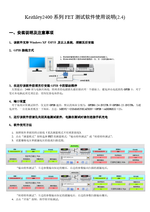
Keithley2400系列FET测试软件使用说明(2.4)一、安装说明及注意事项1,该软件支持Windows XP(SP3)及以上系统,须解压后安装2,GPIB接线方式3,在运行该软件前须另行安装GPIB卡的驱动程序友情提示:2400须与电脑共地线,即两者的电源插头最好插在同一个插座上,避免冲击电流损伤GPIB卡,对于笔记本电脑此项尤须注意,切勿仅靠电池供电。
4,端口设置对于场效应管测试程序,仅支持GPIB通信,默认的地址分别为:GPIB0::24::INSTR和GPIB0::25::INSTR。
为避免冲突,一台设备需要改一下地址,方法:MENU→COMMUNICATION→GPIB→ADDRESS→25。
5,运行该软件前请先关闭其他测试软件,电脑在测试时请勿连接手机充电6,软件使用方法1,按照软件界面的图示接线(更改测量模式不用重新接线);2,点击“测量模式”按钮选择FET的测量模式:“输出特性测试”或“转移特性测试”;3,设置栅极电压和源漏电压的值或扫描范围;“输出特性测试”:左边参数输出恒定的栅压,右边的参数输出扫描的源漏电压;“转移特性测试”:左边的参数输出恒定的源漏电压,右边的参数扫描输出栅压;4,点击“开始”按钮,程序即开始测试;5,按“Ctrol+H”键可获得及时帮助。
7,购买与授权软件可以免费试用30次,试用后软件会在C:\Zeal Young文件夹下自动生成ClientInfo**.prf文件。
如果您觉得好用,可以至本店购买。
购买方法:打开下面链接,付款后将ClientInfo**.prf文件发送至本店,我们会给您密钥。
您再将密钥保存至C:\Zeal Young下,软件即获得授权。
对于FET测试程序,因为要控制两台设备,所以需要两个密钥。
(注:该软件仅绑定了测试设备的生产信息而没有绑定电脑信息,如需更换电脑,按照同样方法操作即可)。
二、使用说明上图是该程序的操作界面,左边是I-V扫描子程序,它可以进行I-V扫描,也可以输出恒定电压并监测电流变化。
KEITHLEY2400源表软件手册(201711)
KEITHLEY(吉时利)2400系列源表测试软件中文说明书(Ver 201711)1目录第一章运行系统要求 (6)一、支持机型 (6)二、计算机要求 (6)第二章软件安装及设置 (7)一、通讯接口 (7)1.接口类型 (7)2.接口设置 (7)3.软件的安装 (7)二、系统参数设置 (8)第三章编辑测试项目 (10)一、什么是测试项目 (10)1.测试项目的定义 (10)2.为什么要使用测试项目 (10)二、建立一个测试项目 (10)三、测试项目的编辑 (13)1.修改步骤参数 (13)2.删除步骤参数 (14)3.调整步骤顺序 (15)四、测试项目的保存 (15)第四章功能设置 (16)一、通用设置 (16)22.接线方式(2、4线制) (17)3.测量速度 (18)4.自动调零 (18)5.滤波 (18)二、单阶恒流输出测量(BiasIMeasureV-Single) (18)1.功能简述 (18)2.参数设置 (18)三、单阶恒压输出测量(BiasVMeasureI-Single) (21)1.功能简述 (21)2.参数设置 (21)四、电流表测量模式(I-METER) (24)3.功能简述 (24)4.参数设置 (24)五、电压表测量模式(V-METER) (25)1.功能简述 (25)2.参数设置 (25)六、电阻测量(Resistance) (27)1.功能简述 (27)2.参数设置 (27)七、多阶恒流输出测量(BiasIMeasureV-Steps) (28)1.功能简述 (28)2.参数设置 (28)八、多阶恒压输出测量(BiasVMeasureI-Steps) (30)32.参数设置 (31)九、电流扫描测量(SweepIMeasureV) (32)1.功能简述 (32)2.参数设置 (33)3.测试数据图形 (34)十、电压扫描测量(SweepVMeasureI) (35)1.功能简述 (35)2.参数设置 (35)3.测试数据图形 (37)十一、太阳能电池IV特性测量(SolarCell-IV) (37)1.功能简述 (37)2.参数设置 (37)3.数据的格式 (39)第五章运行测量 (40)一、开始及终止运行 (40)二、数据及图形的保存格式 (40)第六章常见应用测试 (41)一、二线制与四线制的选择 (41)二、使用自动量程还是固定量程 (42)三、同时测试两个样品 (42)四、用多阶恒压/流进行方波及阶梯波测量 (43)五、任意定制I-V扫描 (44)4六、二极管IV特性测量测量 (45)七、电化学应用 (46)5第一章运行系统要求一、支持机型KEITHLEY2400,2401,2410,2420,2430,2440;如用户需要对KEITHLEY2450图形源表系列进行控制,请联系我们,我们将提供另外一款专门针对2450系列(2450,2460,2461)软件产品供您使用。
吉时利2400数字万用表操作指南
R2 R1 100% R2 (V2 V1 )
6.按 OUTPUT ON/OFF 输出电源。 7.自面板读取量测值。
H.量测百分比
% 儀器讀值 參考值 100 參考值
1. 接线如图 3-1。 2.先按「CONFIG」 ,然后按「FCTN」 ,选择「%DEV」然后按「ENTER」 。 3.设定参考值「REF」 。 4.设定参考高低容许范围「HI TOL」 、 「LO TOL」 。 5.按 SOURCE 6.按 MEAS I 或 V。
1 深圳维立信电子科技有限公司 郑灿城 13424260892 0755-38766766
Keithley 2400 系列 (2400,2410,2420,2430) 多功能电源电表简易操作手册
一、功能:
电压源、电流源、电压表、电流表四合一新型仪器,适用于快速直流测试 可选高电压型 (1100V)、大电流型 (3A) 或大电流脉冲型 (10A) 电源/测量 最大功率: 20W (2400 和 2410), 60W (2420), 100W (2430 直流模式), 1kW (2430 脉冲模式) 五位半电表, 0.012%准确度 可作六线式奥姆测量 程控电流/电压,并可设定箝制准位 最快速度可达 1000 点/秒(GPIB 接口) 内建快速「通过/失效」比较器,适用于自动化质量管理 数字 I/O 可直接与其它仪器沟通 IEEE-488 和 RS-232 界面 除量测电压、电流外,并可直接量测电阻、功率、百分率、补偿电阻(Offset Compensated Ω ) 、变阻器α 值(Varistor α ) 、电压系数(Voltage Coefficient)
图 3-1 二线式接线图
吉时利2400测量软件手册
吉时利(Keithley)2400测量软件手册Ver 2.03目录一、 软件简介 (3)二、 主界面介绍 (3)三、 参数设置 (4)1. 接口选项 (4)2. 测量选项 (4)3. 数据存储选项 (7)四、 测量 (8)2400测量软件(Ver2.02)用于控制美国吉时利(Keithley )公司生产的Keithley2400系列数字源表进行电流(压)源输出,并同时进行测量和数据采集,软件为简体中文界面。
二、 主界面介绍软件运行后,其主界面见下图软件分以下几个功能区【菜单和工具栏】:提供常用的操作的菜单和工具按钮。
【设置区】:用于详细设置各项测量参数,硬件接口及数据存储。
【图形区】:显示测量结果曲线(可根据参数设置显示为IV 、VI 曲线)。
【测量数据区】:以表格的形式显示测量数据。
设置区图形区数据区参数设置用于设置与Keithley2400的接口参数、测量方式、数据等选项,具体见下: 1.接口选项见下图【接口类型】:目前版本只支持RS232接口。
注:在首次使用本软件前,需要将Keithley2400的接口方式改为RS232,具体操作方法请参见Keithley2400用户手册。
【RS232端口】:设置计算机与仪器的进行通讯的RS232端口地址。
2.测量选项见下图【源类型】:目前版本支持设置6种源输出模式,分别是恒定电流源:输出恒定的电流值。
恒定电压源:输出恒定的电压值。
扫描电流源输出(线性):从起始电流扫描到终止电流,每个扫描点之间步长为固定值。
扫描电流输出(对数):从起始电流扫描到终止电流,每个扫描点之间步长以对数级增长。
扫描电压源输出(线性):从起始电压扫描到终止电压,每个扫描点之间步长为固定值。
扫描电压输出(对数):从起始电压扫描到终止电压,每个扫描点之间步长以对数级增长。
选择不同的模式,其设置参数也各不相同。
【输出面板】:Keithley2400既可从前面板(FRONT)输出、也可从后面板(REAR)输出,用户可根据实际接线情况选择,缺省为从前面板输出。
Keithley 2400 Series电源特性说明书
Get more investment protection with the industry’s only fully upgradable scope
–– Upgradable bandwidth –– Upgradable MSO –– Upgradable WaveGen built-in 20 MHz
kit
upgrade
Built-in help language support for English, Japanese, simplified Chinese, traditional Chinese, Korean, German, French, Spanish, Russian, Portuguese, Italian, Polish, and Thai
–
4
8
2
–
2
8
4
–
4
8
2
–
2
8
4
–
4
8
Measurement options
Model DSOX2MEMUP DSOX2MSO DSOX2WAVEGEN DSOXDVM DSOXEDK DSOX2MASK DSOX2SGM DSOX2EMBD DSOX2COMP DSOX2AUTO 33503A N8900A Opt SEC DSOX2BW12 DSOX2BW14 DSOX2BW22 DSOX2BW24 N5467B/C
function generator –– Upgradable integrated digital
voltmeter –– Upgradable measurement applications –– 2-year recommended calibration
Keithley2400系列数字源表测试软件-使用手册3.4
Keithley2400系列数字源表测试软件-使用手册3.4Keithley2400系列数字源表测试软件-使用手册志研科技(淘宝店)出品一、安装说明及注意事项1,该软件支持Windows XP(SP3)及以上系统,须解压后安装(双击运行setup.exe文件)2,在运行该软件前须另行安装GPIB卡或RS-232的驱动程序友情提示:2400须与电脑共地线,即两者的电源插头最好插在同一个插座上,避免冲击电流损伤GPIB卡,对于笔记本电脑此项尤须注意,切勿仅靠电池供电。
3,端口设置(对于GPIB通讯,此项可忽略)若选择RS-232通讯则须进行串口设置,方法:在24xx前面板按“MENU”键,依次选择COMMUNICATION→RS-232(参数确认后24xx会重启)。
重复以上步骤进入设置界面,按“?”键或“?”键向左或向右移动, 按“ENTER”键确认,按“EXIT”键退出。
将BAUD设为9600,Data Bits设为8,Parity 设为None,TERMINATOR设为<CR+LF>,Flow Control设为None(注意:若修改软件面板的串口参数,24xx的串口参数也须做出相应修改;BAUD 越高采样速度越快,但是稳定性会变差,请酌情设置)。
如按MENU键无反应,是因为2400被电脑控制了,按Local键即可解除锁定。
4,端口选择对于GPIB通讯,端口一般为“GPIB0::24::INSTR”,保持默认即可。
对于RS-232通讯,端口可能较多,需要简单辨别一下。
方法:在连接RS-232接口之前,点击“请选择通信端口”的下拉列表(如右图所示),刷新,然后将RS-232接口连接电脑,再点击刷新,新增的COM口即为RS-232的。
5,运行该软件前请先关闭其他测试软件,电脑在测试时请勿连接手机充电,测试过程中请勿触碰通讯线,如果通讯线接触不良可能导致电脑死机。
6,软件使用如软件未提示“端口设置错误!”就可以开始测试了(此软件测试电流的单位为mA,请知悉)。
- 1、下载文档前请自行甄别文档内容的完整性,平台不提供额外的编辑、内容补充、找答案等附加服务。
- 2、"仅部分预览"的文档,不可在线预览部分如存在完整性等问题,可反馈申请退款(可完整预览的文档不适用该条件!)。
- 3、如文档侵犯您的权益,请联系客服反馈,我们会尽快为您处理(人工客服工作时间:9:00-18:30)。
Triggering and Control
2499-DIGIO
8501-1 8501-2 8502 8503 8505
Digital I/O Expander Assembly (not for Model 2401) Trigger Link Cable, DIN-to-DIN, 1m (3.3 ft) Trigger Link Cable, DIN-to-DIN, 2m (6.6 ft) Trigger Link to BNC Breakout Box Trigger Link Cable, DIN-to-Dual BNC, 1m (3.3 ft) Male to 2-Female Y-DIN Cable for Trigger Link
2410
1100V, 1A, 20W SourceMeter SMU Instrument
2410-C 1100V, 1A, 20W SourceMeter SMU Instrument with Contact Check
2420 60V, 3A, 60W SourceMeter SMU Instrument
Power of Five Instruments in One (IV Source, IVR Measure)
The tightly coupled nature of a SourceMeter SMU instrument provides many advantages over solutions configured from separate instruments, such as a precision power supply and a digital multimeter. For example, it provides faster test times by reducing GPIB traffic and simplifies the remote programming interface. It also protects the device under test from damage due to accidental overloads, thermal runaway, etc. Both the current and voltage source are programmable with readback to help maximize device measurement integrity. If the readback reaches a programmed compliance limit, then the source is clamped at the limit, providing fault protection.
Shielded GPIB Cable, 1m (3.3 ft) Shielded GPIB Cable, 2m (6.6 ft) RS-232 Cable Shorting Plug
Communication Interface
KPCI-488LPA IEEE-488 Interface/Controller for the PCI Bus KUSB-488B IEEE-488 USB-to-GPIB Interface Adapter
Ordering Information
2400
200V, 1A, 20W SourceMeter SMU Instrument
2400-C 200V, 1A, 20W SourceMeter SMU Instrument with Contact Check
2401 20V, 1A, 20W SourceMeter SMU Instrument
ACCESSORIES AVAILABLE
TEST LEADS AND PROBES
1754 5804 5805 5808 5809 8607 CA-18-1
2-Wire Universal 10-Piece Test Lead Kit Kelvin (4-Wire) Universal 10-Piece Test Lead Kit Kelvin (4-Wire) Spring-Loaded Probes Low Cost Single-pin Kelvin Probe Set Low Cost Kelvin Clip Lead Set 2-Wire, 1000V Banana Cables, 1m (3.3 ft) Shielded Dual Banana Cable, 1.2m (4 ft)
RACK MOUNT KITS
4288-1 4288-2 4288-4 4288-5 4288-9
Single Fixed Rack Mount Kit Dual Fixed Rack Mount Kit Dual Fixed Rack Mount Kit Shelf Type Side by Side Rack Mounting Kit Dual Fixed Rack Mounting Kit
Keithley’s Series 2400 Source Measure Unit (SMU) Instruments are designed specifically for test applications that demand tightly coupled sourcing and measurement. All SourceMeter models provide precision voltage and current sourcing as well as measurement capabilities. Each SourceMeter SMU instrument is both a highly stable DC power source and a true instrument-grade 6½-digit multimeter. The power source characteristics include low noise, precision, and readback. The multimeter capabilities include high repeatability and low noise. The result is a compact, single-channel, DC parametric tester. In operation, these instruments can act as a voltage source, a current source, a voltage meter, a current meter, and an ohmmeter. Manufacturers of components and modules for the communications, semiconductor, computer, automotive, and medical industries will find the SourceMeter SMU instruments invaluable for a wide range of characterization and production test applications.
SMU INSTRUMENTS
Series 2400 SourceMeter® SMU Instruments
Tightly coupled precision sourcing and measurement
Tightly coupled precision sourcing and measurement
• Seven models: 20–100W DC, 1000W pulsed, 1100V to 1µV, 10A to 10pA
• Source and sink (4-quadrant) operation
• 0.012% basic measure accuracy with 6½-digit resolution
• Programmable DIO port for automation/handler/prober control (except Model 2401)
• Standard SCPI GPIB, RS-232 and Keithley Trigger Link interfaces
• Keithley LabTracer 2.0 I-V curve tracing application software (download)
Series 2400 SourceMeter® SMU Instruments
Tightly coupled precision sourcing and measurement
Tightly coupled precision sourcing and measurement
• Five instruments in one (IV Source, IVR Measure)
• 2-, 4-, and 6-wire remote V-source and measure sensing
• 1700 readings/second at 4½ digits via GPIB
• Pass/Fail comparator for fast sorting/binning
• Available high speed sense lead contact check function
SWITCHING HARDWARE
7001 7002 7019-C 7053
Two-Slot Switch System Ten-Slot Switch System 6-Wire Ohms Switch Card High-Current Switch Card
CABLES/ADAPTERS