2007款丰田凯美瑞2azfe发动机起动系统维修手册(英文版)(可编辑)
凯美瑞使用手册

/guide/cxpj/122410.shtml
9/29/2009
页码,5/10 9/29/2009
广汽丰田凯美瑞-初级使用指南 卓众汽车网
该车驾驶员座椅为8方向电动调整,并配有腰部支撑。 副驾驶席座椅可在后排进行调整。 空调系统
/guide/cxpj/122410.shtml
页码,6/10 9/29/2009
广汽丰田凯美瑞-初级使用指南 卓众汽车网
巡航控制
/guide/cxpj/122410.shtml
9/29/2009
广汽丰田凯美瑞-初级使用指南 卓众汽车网
1 巡航系统关闭 2 巡航系统开启 3 设定巡航速度/减速 4 恢复巡航速度/加速 座椅调整
/guide/cxpj/122410.shtml
提交查询
■ 友情推荐
反淘宝联盟的报复方式 反淘宝联盟 幕后策划者究竟是谁? 塑新貌 强筋骨 铸灵魂—福瑞迪 1.6AT测评 全新雷克萨斯ES240/ES350深圳上市发布
9/29/2009
广汽丰田凯美瑞-初级使用指南 卓众待解决
l 5 请问这款车在贵州省内有无经… l 5 标致307和福克斯,谁的操控性… l 汽车电子零件目录大全2009年最新版
广汽丰田凯美瑞-初级使用指南 卓众汽车网
页码,1/10
■ 您现在的位置:首页 >> 用车 >> 用车建议
卓众通行证 | 用户:
密码:
验证码:
g f e d c b 记住我 登陆
首页
导购
新车
试驾
用车
资讯
专题
图片对比 · 车型库 · 行情 · 图库 · 图评 · 故障报告 · 用车成本 · 视频 · Auto知道 · 汽车帮
凯美瑞维修手册-3-5

ৢ䮼䫕ℶԡ㕂ᓔ݇ ˄/+ǃ5+˅
B150383E01
防盗 – 防盗系统 (配备智能进入和起动系统)
TD–5
系统说明
参考下表中的报警方法和报警时间:
1. 防盗系统概要
· 通过发射器锁止车门时,可以设定防盗系统。
· 当防盗系统处于警戒状态时,如果有人企图强行打开
或锁定任何车门、发动机盖或行李厢门,警报功能将
TD-1 TD-4 TD-5 TD-8 TD-9 TD-11 TD-13 TD-14 TD-16 TD-19 TD-21 TD-24 TD-27
TD-30
TD-33 TD-34
TD
TD-37
TD-38
TD-40
TD-42
TD-42
TD-44
TD-46
TD-48
TD-52
TD-56
TD-59
TD-62 TD-63 TD-64 TD-64
安全喇叭总成
组件 . . . . . . . . . . . . . . . . . . . . . . . . . . . . . 拆卸 . . . . . . . . . . . . . . . . . . . . . . . . . . . . . 检查 . . . . . . . . . . . . . . . . . . . . . . . . . . . . . 安装 . . . . . . . . . . . . . . . . . . . . . . . . . . . . .
发动机盖控灯开关
六代凯美瑞点火系统

IG2AZ-FE 点火点火系统注意事项 . . . . . . . . . . . . . . . . . . . . . . . . . . . IG-1部件位置 . . . . . . . . . . . . . . . . . . . . . . . . . . . IG-2系统图 . . . . . . . . . . . . . . . . . . . . . . . . . . . . IG-3车上检查 . . . . . . . . . . . . . . . . . . . . . . . . . . .IG-5点火线圈组件 . . . . . . . . . . . . . . . . . . . . . . . . . . . . . IG-9拆卸 . . . . . . . . . . . . . . . . . . . . . . . . . . . . . IG-10安装 . . . . . . . . . . . . . . . . . . . . . . . . . . . . .IG-10IG2AZ-FE 点火 – 点火系统IG–1IG点火系统注意事项1.点火开关的表述方法(a)根据车辆规格的不同,此车型所用的点火开关的类型也不同。
下表中列出的表述方法为本节中所用到的。
开关类型点火开关(位置)点火开关(状态)表述方法点火开关 OFFLOCK OFF 点火开关 ON (IG)ON ON (IG)点火开关 ON (ACC)ACC ON (ACC)起动发动机START起动IG–22AZ-FE 点火 – 点火系统IG部件位置2AZ-FE 点火 – 点火系统IG–3IG系统图IG–42AZ-FE 点火 – 点火系统IG2AZ-FE 点火 – 点火系统IG–5IG车上检查1.检查点火线圈总成并进行火花测试备注:在这一部分中,“Cold”(冷)和 “hot”(热)指的是线圈温度。
丰田车系统保险丝、继电器中英文名称对照-精心整理含考核
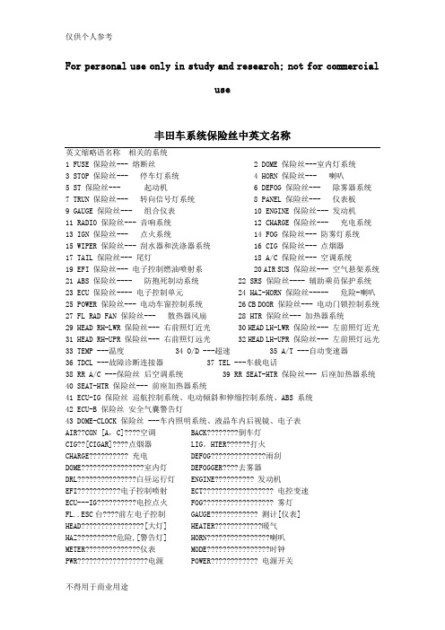
For personal use only in study and research; not for commercialuse丰田车系统保险丝中英文名称英文缩略语名称相关的系统1 FUSE 保险丝--- 熔断丝2 DOME 保险丝---室内灯系统3 STOP 保险丝--- 停车灯系统4 HORN 保险丝--- 喇叭5 ST 保险丝--- 起动机6 DEFOG 保险丝--- 除雾器系统7 TRUN 保险丝--- 转向信号灯系统8 PANEL 保险丝--- 仪表板9 GAUGE 保险丝--- 组合仪表10 ENGINE 保险丝--- 发动机11 RADIO 保险丝--- 音响系统12 CHARGE 保险丝--- 充电系统13 IGN 保险丝--- 点火系统14 FOG 保险丝--- 防雾灯系统15 WIPER 保险丝--- 刮水器和洗涤器系统16 CIG 保险丝--- 点烟器17 TAIL 保险丝--- 尾灯18 A/C 保险丝--- 空调系统19 EFI 保险丝--- 电子控制燃油喷射系20 AIR SUS 保险丝--- 空气悬架系统21 ABS 保险丝---- 防抱死制动系统22 SRS 保险丝---- 辅助乘员保护系统23 ECU 保险丝---- 电子控制单元24 HAZ-HORN 保险丝----- 危险-喇叭25 POWER 保险丝--- 电动车窗控制系统26 CB DOOR 保险丝--- 电动门锁控制系统27 FL RAD FAN 保险丝--- 散热器风扇28 HTR 保险丝--- 加热器系统29 HEAD RH-LWR 保险丝--- 右前照灯近光30 HEAD LH-LWR 保险丝--- 左前照灯近光31 HEAD RH-UPR 保险丝--- 右前照灯远光32 HEAD LH-UPR 保险丝--- 左前照灯远光33 TEMP ---温度34 O/D ---超速35 A/T ---自动变速器36 TDCL ---故障诊断连接器37 TEL ---车载电话38 RR A/C ---保险丝后空调系统39 RR SEAT-HTR 保险丝--- 后座加热器系统40 SEAT-HTR 保险丝--- 前座加热器系统41 ECU-IG 保险丝巡航控制系统、电动倾斜和伸缩控制系统、ABS 系统42 ECU-B 保险丝安全气囊警告灯43 DOME-CLOCK 保险丝 ---车内照明系统、液晶车内后视镜、电子表AIR??CON [A,C]????空调BACK????????倒车灯CIG??[CIGAR]????点烟器LIG。
凯美瑞维修手册

最小压力 :
980 kPa (10 kgf/cm2, 142 psi)
各气缸之间的差值 :
A001037
100 kPa (1.0 kgf/cm2, 14 psi)
备注 :
· 请使用电力充足的蓄电池,以使发动机转速
达到 250 rpm 或更高。
· 用同样方法检查其他气缸的压缩压力。
· 测量必须尽可能快。
EM-115 EM-120 EM-130
重新装配 . . . . . . . . . . . . . . . . . . . . . . . . . . . EM-143
EM
DLC3 ᱎ㛑⌟䆩Ҿ
DLC3
CG
1 2 3 4 5 6 78 9 10 111213 141516
TC
2AZ-FE 发动机机械 – 发动机
发动机总成
组件 . . . . . . . . . . . . . . . . . . . . . . . . . . . . . 拆卸 . . . . . . . . . . . . . . . . . . . . . . . . . . . . . 检查 . . . . . . . . . . . . . . . . . . . . . . . . . . . . . 安装 . . . . . . . . . . . . . . . . . . . . . . . . . . . . .
凸轮轴
组件 . . . . . . . . . . . . . . . . . . . . . . . . . . . . . 拆卸 . . . . . . . . . . . . . . . . . . . . . . . . . . . . . 检查 . . . . . . . . . . . . . . . . . . . . . . . . . . . . . 安装 . . . . . . . . . . . . . . . . . . . . . . . . . . . . .
丰田普瑞维亚PREVIA 维修教程-[2AZ-FE]发动机
![丰田普瑞维亚PREVIA 维修教程-[2AZ-FE]发动机](https://img.taocdn.com/s3/m/1a0f35a00342a8956bec0975f46527d3240ca62d.png)
Engine ECU locates in engine compartment发动机ECU 在发 动机室
CAN communication for diagnosis CAN通信用于诊断
车型概述
对技师
2AZ-FE 发动机
底盘
Engine Proper发动机本体
减速
怠速Idling
发电模式
SOC*
目标 SOC
调整 SOC(充电状
态)
高
产生电压 Hi Generated
Voltage Lo
低
低LO
调整 SOC(充电
状态)
控制区域 Control Region
高HI
调整 SOC(充电
状态)
没有充电控 制 Control
*:充电状态State Of Charge
Cylinder Block缸体 Water jacket spacer水套隔板
Body车身
车身电器 -Q -V -_
水套隔板 Water Jacket Spacer
With有
无
水套隔板减少 冷却液流动
过冷 Overcool
低机油粘性
低磨擦
高机油粘性
高磨擦
车型概述
对技师
2AZ-FE 发动机
底盘
pulley当拆装发电机皮带轮时使用SST
Remove拆
SST 09820-63020
(2 件parts)
轴Shaft 皮带轮Pulley
SST
车型概述
对技师
2AZ-FE 发动机
底盘
维修要点 (充电系统Charging System)
凯美瑞2AZ-FE型发动机异响的检修
1 . 它 : 排 气 系 统 漏 L 、 1其 进 - 声 回 -
火声 、 炮 声等。 放
Hale Waihona Puke 希 望通过 一例 凯 美瑞 轿车 2 — AZ F E型 发 动 机 异 响 的 检 修 来 与 大 家 分 享发 动机异 响检修 经验 。 故 障现象 :
一
障代 码 。
3故 障 部 位 确 认 一 小 异 响 范 围 . 缩
1试车 , 们 确认 到 以上故 障现 ) 我 象 , 断异 响 来 源 于 发 动 机 舱 。 判 2) 障 发 生 条 件 : 故
② 分 别 断 N .、 o2
3 4气 缸 喷 油 器 , 嗒 、 “
嗒 ” 依 然 存 在 。 确 认 声
① 打 开 发 动 机 舱 , 速 时 我 们 在 怠
敲 击声 、 震 等。 爆
3正 时 皮 带 或 链 异 响 。 .
4气 门 异 响 。 .
1) 动 机 机 油 发
① 检 查发动 机机 油有 无泄 漏 : 无
泄 漏 , 常。 正
5活 塞 销 运 动 部 件 异 响 。 .
6活 塞 与 气 缸 敲 击 异 响 。 .
② 检查 发动机 机 油油位 : 动机 发
发 动机 附近不 能 听到 “ 嗒 ” 响声 。 嗒 异 怠速 急 加油 时 , 听见连 续 的 “ 嗒 ” 能 嗒
声。
异 响 来 自 No1气 缸 。 . ③ 利 用听诊 法 , 进
一
步 确 认 No1气 缸 异 .
在 NoI 气 缸 下 .
响。
・
② 车 辆 正 常 行 驶 中 ,急 加 速 时 ,
故 障诊断 : 1故 障 再 现 : .
丰田卡罗拉2007(COROLLA2007)整车电路图手册
6
COROLLA_EWD-B.fm Page 7 Saturday, May 12, 2007 2:50 PM
B
[O] : 解释系统概述。
[P] : 显示系统电路中的零件在车辆上的位置的参考页码。
例 : 零件 “H4”( 灯故障传感器 ) 在手册的 36 页。
* 该代码的第一个字符表示指示线束的字母,第二个字符表示与线束连接的零件的系列号。
电源 ( 电流流程图 ) . . . . . . . . . . . . . . . . . . . . . . . . J . . . . 336
连接器表 . . . . . . . . . . . . . . . . . . . . . . . . . . . . . . . . K . . . . 344
2
COROLLA_EWD-B.fm Page 3 Saturday, May 12, 2007 6:37 PM
如何使用本手册 B 本手册将车辆上安装的电路按所属系统划分,提供各系统电路的资料。 各系统电路的实际配线是指从蓄电池开始的电源点到各搭铁点的配线。 ( 所有电路图 均显示所有开关关闭时的状态。 ) 对任何故障进行故障排除时,首先要了解故障电路的工作原理 ( 参见 “系统电路”一 章 ),了解对此电路供电电源的工作原理 ( 参见“电源”一章 ) 和搭铁点的工作原理 ( 参 见 “搭铁点”一章 ),同时还可参见 “系统概述”来了解电路的工作原理。 了解电路原理后,可以开始对故障电路进行故障排除,找出故障原因。利用 “继电器 位置分布图”和 “电路图”来找出各个零件、接线盒和线束连接器、线束和线束连接 器及系统电路的搭铁点。为使您更清楚地了解接线盒内的连接情况,本手册还提供了 每个接线盒内部的电路图。 在各系统电路中用箭头 ( 从 ___,到 ___ ) 标示与各系统相关的配线。如果需要了解总 体连接情况,请参见本手册末的 “总电路图”。
丰田凯美瑞维修手册说明书
Toyota Camry Factory Repair Manuals
Toyota Camry Factory Repair Manuals
For North American models
I am not responsible for any damage you may cause as a result of using these files. PLEASE do not provide links to specific files. Things may change around. Link to this page instead.
q Fluid specs - applicable for 1994-2005 Toyota's and Scion's, not including Scion tC q Harness Repair Manual Updated 11/25/2006
/~tongt/camry/ (2 of 2)11/26/2006 11:09:42 PM
manuals for most manuals q Gen 6 Camry (2007- ) - Complete 2007 repair manuals, electrical wiring diagrams
凯美瑞维修手册
《凯美瑞维修手册》一、引言凯美瑞作为一款知名的豪华车型,受到了许多车主的喜爱。
但是,随着使用时间的增长,车辆出现故障的可能性也越来越大。
因此,掌握一些基本的维修知识是非常必要的。
本手册将为车主提供一些关于凯美瑞维修的基本指导,并帮助车主了解如何应对常见的故障和维护需求。
二、常见故障及解决方法1.发动机无法启动如果您的凯美瑞发动机无法启动,有几个可能的原因需要考虑。
首先,请检查电池是否正常,并确保电池终端清洁。
如果电池工作正常,可能是由于点火系统的故障导致的。
您可以检查点火线圈、火花塞和点火线是否受损。
如果有发现任何问题,请及时更换或修复。
2.刹车失灵刹车失灵是一种相当危险的情况,需要立即采取行动来解决。
如果您发现车辆的刹车出现问题,您可以尝试踩下几次刹车踏板来建立刹车压力。
如果刹车失灵的原因是刹车液耗尽或刹车管道破裂,您需要在安全的情况下停下车辆,并及时联系专业维修人员进行维修。
3.制冷系统故障如果您发现您的凯美瑞空调制冷效果不佳,可能是由于系统漏气等问题引起的。
您可以先检查制冷剂是否不足,并检查系统中的管道是否有任何泄漏迹象。
如果有发现任何问题,请务必寻求专业的维修帮助,以避免加重故障或损坏其他零部件。
三、常见维护需求1.更换机油和机滤提醒车主每隔一定的时间或行驶里程更换机油和机滤是非常重要的。
定期更换机油和机滤可以保持发动机的正常运转,并延长发动机的使用寿命。
请按照车辆的保养手册上的建议来进行更换,并选择适当的机油和机滤。
2.轮胎保养轮胎是车辆行驶中承受最大压力的部件之一。
定期检查轮胎的胎压和磨损情况是非常重要的。
确保轮胎胎纹深度合适,并遵循制造商的建议来调整胎压。
此外,不要忘记定期进行轮胎的换位操作,以保持轮胎的均匀磨损。
3.保养电池电池是车辆正常运转所必需的组件之一。
定期检查电池的连接器是否松动,并清洁终端以确保良好的电池连接。
如果电池终端出现腐蚀或损坏,及时更换,以避免电流传导失效。
四、结论本手册提供了一些有关凯美瑞维修和保养的基本指导。
- 1、下载文档前请自行甄别文档内容的完整性,平台不提供额外的编辑、内容补充、找答案等附加服务。
- 2、"仅部分预览"的文档,不可在线预览部分如存在完整性等问题,可反馈申请退款(可完整预览的文档不适用该条件!)。
- 3、如文档侵犯您的权益,请联系客服反馈,我们会尽快为您处理(人工客服工作时间:9:00-18:30)。
2007款丰田凯美瑞2AZ-FE发动机起动系统维修手册(英文版)ST–12AZ-FE STARTING – STARTINGSYSTEM2AZ-FE STARTINGENGINESTARTING SYSTEMPARTS LOCATIONSTARTER RIAPATPARKNEUTRAL EPOSITION SWITCH R ENGINE ROOM RB-STARTER RELAYECM-STAM2 FUSEA -ALT FUSETOINSTRUMENT PANEL JB Y-AM1 FUSE OTSTMT IGNITION SWITCH CLUTCH START SWITCHA135518E01ST–22AZ-FE STARTING –STARTING SYSTEMSYSTEM DIAGRAM224C1L BParkNeutralPPosition ECMNSwitch248R A24 STAA22IE23 Clutch StartSwitchIgnition Switch A11P1 2EACCR 2 52AM1 IG1 C24 NSW4ST1STAM1 AM2 IG2 3 A5 T 1 2ST275 3OYALT STAM2 OT StarterFL MAIN1 1 1D1 C29 C31 2MST Battery1 MT2 ATA135060E01ST–32AZ-FE STARTING –STARTER2AZ-FE STARTINGENGINESTARTERCOMPONENTSAIR CLEANER CAP SUB-ASSEMBLYAIR CLEANER FILTER ELEMENT50 51 44 inlbfRSTARTER 50 51 44 inlbfI x3ASSEMBLYAfor Manual Transaxle 98 100 87 inlbf PE12 120 9 RCLUTCH FLEXIBLE AIRCLEANER AIR CLEANER CASEx2HOSE BRACKET INLET ASSEMBLY SUB-ASSEMBLY37 380 28 ATOYOTSTNm kgfcm ftlbf Specified torqueA133564E01ST–42AZ-FE STARTING – STARTER STARTER ARMATURE ASSEMBLYSTARTER COMMUTATOR END FRAME ASSEMBLYSTARTER COMMUTATOREND FRAME COVER60 61 53 inlbfSNAP RINGREPAIR SERVICEWASHERSTARTER KIT R-PLUNGER I-RETURN SPRING A60 61 53 inlbf-MAGNETIC SWITCH PER75 76 66 inlbf ATO 10 102 7YOTMOTOR TERMINAL STARTER KITSTPLANETARY GEARNm kgfcm ftlbf Specified torqueSTARTER ARMATUREPLATENon-reusable partSTARTER YOKE ASSEMBLYApply High-temperature greaseA134900E01ST–52AZ-FE STARTING – STARTERREMOVAL1 DISCONNECT CABLE FROM NEGATIVE BATTERYTERMINAL2 REMOVE AIR CLEANER INLET ASSEMBLY Seepage EM-943 REMOVE AIR CLEANER CAP SUB-ASSEMBLY Seepage ES-4164 REMOVE AIR CLEANER CASE SUB-ASSEMBLY Seepage EM-955 REMOVE STARTER ASSEMBLY for ManualTransaxlea Disconnect the terminal 50 connector from thestarter assemblyb Remove the nut and disconnect the wire harnessfrom terminal 30 RIA133565 Ac Remove the 3 bolts clutch flexible hose bracket andPstarter assemblyERABracketA133566E01TO6 REMOVE STARTER ASSEMBLY for AutomaticY TransaxleO a Disconnect the terminal 50 connector from thestarter assemblyT b Remove the nut and disconnect the wire harnessfrom terminal 30A134876c Remove the 2 bolts and starter assembly STA134877ST–62AZ-FE STARTING –STARTERDISASSEMBLY1 REMOVE REPAIR SERVICE STARTER KITa Remove the nut and disconnect the lead wire fromterminal CA079718E05b Remove the 2 screws that hold the magnetic switchto the motor terminal starter kitc Remove the repair service starter kitd Remove the return spring and the plunger from therepair service starter kitRIA079719E05 A2 REMOVE STARTER YOKE ASSEMBLYPa Remove the 2 through bolts and pull out the starteryoke assembly together with the starter commutatorEend frame assemblyRAA079720E05TO b Remove the starter yoke assembly from the starterY commutator end frame assemblyOTA079721E033 REMOVE STARTER ARMATURE PLATEST a Remove the starter armature plate from the starteryoke assemblyA079722E04ST–72AZ-FE STARTING – STARTER4 REMOVE STARTER COMMUTATOR END FRAMECOVERa Using a screwdriver remove the starter commutatorend frame coverA079723E035 REMOVE STARTER ARMATURE ASSEMBLYa Using snap ring pliers remove the snap ring andplate washerSnap Ring Pliersb Remove the starter armature assembly from thecommutator end frame assemblyRIA082440E07 A6 REMOVE PLANETARY GEARPa Remove the 3 planetary gears from the motorterminal starter kitERAA081167E03TOYOTSTST–82AZ-FE STARTING –STARTERINSPECTION1 INSPECTSTARTER ASSEMBLYCAUTIONMake sure to complete each of the following testswithin 5 seconds to prevent the coil from burningouta Perform pull-in test1 Disconnect the lead wire from terminal CTerminal CA133511E012 Connect the battery to the magnetic switch asRshown in the illustration Check that the clutchIpinion gear moves outwardTerminal CIf the clutch pinion gear does not moveAoutward replace the repair service starter kitPEBody RTerminal 50A133512E01bPerform hold-in testA 1 Disconnect the negative - terminal lead fromT terminal C under the conditions for pull-in testCheck that the pinion gear remains outTerminal C O If the clutch pinion gear moves inward replaceY the repair service starter kitOBody Terminal 50 TA133513E01c Inspect clutch pinion gear return1Disconnect the negative - lead from thestarter body Check that the clutch pinion gearmoves inwardTerminal C If the clutch pinion gear does not move inwardSTreplace the repair service starter kitdPerform no-load performance test1Connect the field coil wire to terminal C with theBody Terminal 50 nut Make sure that the lead is not groundedA133514E01 Torque 10 Nm 102 kgfcm 7 ftlbf2 Clamp the starter in a viseST–92AZ-FE STARTING –STARTER3 Connect the battery and an ammeter to thestarter as shown in the illustrationAmmeter 4 Check that the starter rotates smoothly andsteadily with the clutch pinion gear extendedTerminal 30 Checkthat the ammeter reads the specifiedcurrentSpecified currentCondition Specified conditionat 115 V 90 A or lessIfthe result is not as specified overhaul thestarter assemblyBodyTerminal 50A133510E012 INSPECT REPAIR SERVICE STARTER KITa Check the plunger R1 Push in the plunger and check that it returnsquickly to its original positionIIf necessary replace the repair service starterAkitPEA058586E04 Rb Inspect the resistance of the pull-in coil1 Using an ohmmeter measure the resistanceTerminal CA between terminals 50 andCTStandard resistanceTesterconnection Specified conditionO Terminal 50 - Terminal C Below 1Terminal 50 Y If theresistance is not as specified replace theBelow 1 ΩOrepair service starter kitT A079725E08c Inspectthe resistance of the hold-in coilBody1 Using an ohmmeter measure the resistanceBelow 2 Ωbetween terminal 50 and the switch bodyStandard resistanceTester connection Specified conditionTerminal 50 - Switch body Below 2 STTerminal 50 If the resistance is not as specified replace therepair service starter kitA079726E073 INSPECT STARTER ARMATURE ASSEMBLYa Check the commutator surface for dirt or burningIf the surface is dirty or burnt smooth the surfacewith400-grit sandpaper or leatherST–102AZ-FE STARTING –STARTERInspect the resistance of the commutator1 Using an ohmmeter measure the resistancebetween the segments of the commutatorStandard resistanceTester connection Specified conditionBelow 1 Ω Segment - Segment Below 1If the resistance is not as specified replace theSegmentstarter armature assemblyA058372E042Using an ohmmeter measure the resistancebetween the commutator and armature coil10 kΩor Higher coreStandard resistanceTesterconnection Specified conditionCommutator Commutator -Armature coil core 10 k or higherCoil Core If the resistance is not as specified replace theRstarter armature assemblyIA058373E04Ac Usingvernier calipers measure the commutatorPdepthSpecified depthE31 mm 0122 inRimum depthDepth38 mm 0150 inIf the depth is greater than the imum replaceAthe starter armature assemblyA058584E09T4 INSPECT STARTER COMMUTATOR END FRAMEOY ASSEMBLYa Check the brush lengthO 1 Using vernier calipers measure the brushTLengthlengthSpecified length90 mm 0354 inimum length40 mm 0157 inA076677E10 If the length is less than the minimum replacethe starter commutator end frame assemblyST b Check the resistance10 kΩ or Higher 1 Using an ohmmeter measure the resistancebetween the positive and negative -brushesResistance10 k or higherIf the resistance is not as specified repair orreplace the starter commutator end frameassemblyA079766E10ST–112AZ-FE STARTING –STARTER5 INSPECT MOTOR TERMINAL STARTER KITLocka Check the starter clutch1 Rotate the clutch pinion gear counterclockwiseand check that it turns freely Try to rotate theclutch pinion gear clockwise and check that itlocksIf necessary replace the motor terminal starterkitFreeA081655E05REASSEMBLY1 INSTALL PLANETARY GEARApply Grease a Applyhigh-temperature grease to the planetarygears andpin parts of the planetary shaftb Install the3 planetary gears to the motor terminalstarter kit RA081656E06IA2 INSTALL STARTER ARMATURE ASSEMBLYa Applyhigh-temperature grease to the plate washerPand the armature shaftSnap Ring Pliers Eb Install the starter armature assembly to the startercommutator end frame assemblyRc Using snap ring pliers install the plate washer and anew snap ringAA082440E08TO d Using vernier calipers measure the snap ringLength imum lengthY 50 mm 0197 inO If the length is greater than the imum replaceT the snap ring with a new oneA058810E14。