欧特尔电磁脉冲阀(Valves_China)
电磁阀 VUVG 阀岛 VTUG - 产品目录 - Festo

电磁阀VUVG/阀岛VTUGSubject to change –2017.062→Internet:/catalogue/...电磁阀VUVG主要特性创新通用可靠易安装•可设置为内先导或外先导,用于板式阀阀组•通过电接口插件可方便地更换连接技术•最大压力10bar •结构特点:–活塞滑阀,带密封圈(VUVG-LK,VUVG-BK)–活塞滑阀,带密封阀芯(VUVG-L,VUVG-B)•多种阀功能•可选快插接头•管式阀•板管式阀可用作气路板集成安装•M5和M7管式阀可组合在一块气路板上•气路板带多个压力分区•IP40,IP65•坚固耐用的金属元件–阀–气路板•快速排除故障,得益于360°LED 显示•可快捷地更换阀片,维护便利•可选手控装置:按钮式,封盖式,按钮式/锁定式或锁定式(不带附件)•牢固地安装到墙面或H 型导轨•随带螺丝和密封件,安装方便•通过电接口插件可方便地更换连接技术•标签支架,用于阀的标签阀岛配置器CAD 相关数据→阀岛配置器帮助您选择正确的阀岛VTUG ,订购正确的产品更方便。
阀岛VTUG 通过订货代码订购。
所有阀岛供货时已装配完毕并单独做过测试。
最大限度减少了装配和安装时间。
订货系统,用于阀岛VTUG →Internet:vtug-V-新产品VUVG-LK,VUVG-BK2017.06–Subject to change 3Internet:/catalogue/...电磁阀VUVG主要特性–气动元件单个阀和阀岛管式阀用作单个阀管式阀VUVG-LK/VUVG-L管式阀可无需气动耦合就可使用。
所有气接口位于阀上,可配备接头/气管。
电接口有多种不同的电接口插件可选。
如果使用过了特殊密封套件,管式阀VUVG 还可作为半管式阀安装在气路板(气动耦合)上。
板管式阀可用作气路板集成安装半管式阀VUVG-S阀岛VTUG 由半管式阀VUVG-S 组成对于半管式阀,进气口(1,3和5)通过气动耦合(如,气路板)与阀连接。
意大利autel公司简介

意大利Autel(欧特尔)公司是欧洲一家有着30多年开发、研制、生产、销售高品质的除尘设备专用脉冲阀、清灰控制仪、粉尘监测仪及相关除尘器设备电控元件的专业制造商。
自1980年成立至今,公司一直秉承着专业、专注、创新、求实的理念,首创了“高速自复式膜片”并应用于全系列脉冲阀上,第二代智能脉冲控制仪也实现了量化生产。
Autel(欧特尔)公司凭借着设备运行精确稳定的监控系统、高品质脉冲清灰系统,提高了除尘设备的效率,降低了能源的损耗,赢得了同行业和客户的认可,并连续多年在欧洲同行业的技术及销量雄居先驱领导地位。
在技术领先,产品适销的情况下,Autel(欧特尔)公司一如既往执行的(TQM)公司优品管理系统,并在2001年3月取得了欧洲DNV的UIN EN ISO 9001认证。
为客户提供稳定优良的产品,不断精益求精,让客户得到最大的满意是Autel(欧特尔)公司的核心精神和目标。
公司过往业绩:Autel欧特尔脉冲阀在全球销售网络上已经成功销往意大利,德国,西班牙,美国,印度,印尼,巴西等国,特别是在水泥行业设备中取得令人满意的成绩,以下为几家实际采用欧特尔脉冲阀及相关智能脉冲控制仪的厂家名称:1)AAF-加拿大设备制造商2)FL smiDTH3)THERMAX-印度最大除尘设备制造商4)LAFARGE-拉法基水泥设备厂5)ITALCEMENTI-意大利最大水泥设备厂6)REDECAM以上皆安装了AUTEL欧特尔脉冲阀以及其脉冲阀控制仪等产品,并已实际在设备上运转。
以下附上公司及产品实际的照片:Autel欧特尔公司在意大利的厂房外观。
脉冲阀系列产品,从3/4寸到3寸淹没阀。
阀门内部独特构造,有更大充气量。
独特的几何膜片设计,高速自复式膜片能在瞬间达到最高峰值。
拉法基水泥厂在罗马尼亚的设备上装配的就是Autel 欧特尔脉冲阀、气包系列及其相关控制仪元件。
此套设备配置有Autel欧特尔智能脉冲阀控制仪。
拉法基公司感谢Autel 欧特尔公司在除尘设备低压脉冲阀设备上所给予的技术支持。
电磁阀-上海立盾阀门制造有限公司

电磁阀
电磁 阀分为常 闭和常开 二种;一般 选用常闭 型,通电 打开,断电 关闭;但在 开启时间 很长 关闭 时很短 时要选 用常 开型了 。 寿命 试验 ,工厂 一般属 于型 式试验 项目, 动作 时 一 电磁 阀的 最 三、安全 性 确切 地说 我国还 没有电 磁阀 的专业 标准 ,因 此选 用电磁 阀厂家 时慎 重。 间很短 频率较高 时一般选 取直动式 ,大口 径选用快 速系列。 般电 磁阀 不防水 ,在条 件不 允许时 请选用 防水 型,工 厂可以 定做 。 情况 。
工作 压差,管路 最高压差 在小于 0.04MP a
时 应 选 用 如 ZS,2W,ZQDF,ZCM 系 列 等 直 动 式 和 分 步 直 动 式 ; 最 低 工 作 压 差 大 于 0.04MPa 时可 选用先导 式(压差 式)电磁 阀;最高 工作压差 应小于电 磁阀的最 大标定 压力 ; 一般 电磁阀都 是单向工 作, 因此 要注意是 否有反压 差, 如有 安装止回 阀。 流 体 清洁 度 不高 时应 在 电磁 阀 前安 装过 滤 器, 一 般电 磁阀 对 介质 要 求清 洁度 要 好。 注意 流量孔径 和接管口径 ;电 磁阀一般 只有开关 两位控制 ;条件允 许请安装 旁路管, 便于 维修 ;有 水锤 现象时要 定制 电磁阀 的开闭 时间 调节。 阀的 影响 右, 必须注意 交流起动 时 VA 值较 高。 二、 可靠性 注意 环境 温度对 电磁 电源 电流和消 耗功率应 根据输出容量 选取, 电源 电压一般 允许±10%左
工作原理
电磁 阀里有密 闭的腔, 在不同位 置开有通 孔,每个 孔都通向 不同
电磁阀
的油 管,腔中 间是阀,两面 是两块电磁 铁,哪面 的磁铁线 圈通电阀体 就会 被吸引到 哪 边,通过 控制阀体 的移动来 挡住或漏 出不同的 排油的孔 ,而进 油孔是常 开的,液压 油 就会 进入不同 的排油管 ,然后通 过油的压 力来推动 油缸的活塞 ,活 塞又带动 活塞杆, 活塞 杆带动 机械装置 动。这样 通过控制 电磁铁的 电流通断 就控制了 机械运动 。
Belimo Energy Valve 特定控制阀(CCV)手册说明书

Belimo Energy Valve TM web server manual Characterised control valve (CCV) with adjustable flow rate and sensor-operated flow control, power control, and power and energy-monitoring functionContentsGeneral 2 Web server 3 Attachment 20Characterised control valve (CCV) with adjustable flow rate andsensor-operated flow control, and power and energy-monitoringGeneralVersions Information ∙This manual relates to the following listed products with a production date from 31stMarch 2017.◦ Belimo Energy Valve TM DN15 to DN50▫ EV0..R+(K)BAC(1)◦ Belimo Energy Valve TM DN65 to DN150▫ P..W..EV-(K)BAC∙Earlier versions might have different views and functions. In case of doubt, pleasecontact your Belimo Representative.Requirements ∙For a direct-access a PC with an installed web browser and a network cable (RJ45) isneeded.∙The following web browsers are supported:◦ Microsoft Internet Explorer◦ Mozilla Firefox◦ Safari on platform iOS◦ Standard web browser on platform Android:▫ Gingerbread▫ Honeycomb▫ Ice Cream Sandwich▫ Jelly Bean∙To display the trend views in the web browser, the "Adobe Flash Player" has to beinstalled. Download of the newest version: /de/products/flashplayer/∙The current version of Java has to be installed. Download:/de/download/.Access to the Energy Valve∙Connect the PC/Laptop to the Energy Valve with the RJ45 cableConnection∙Note: The Energy Valve must be supplied with voltage.EV..R+BAC / P6..W..EV-BAC Characterised control valve (CCV) with adjustable flow rate andsensor-operated flow control, and power and energy-monitoringAccess to the Energy Valve by means of a"Peer to Peer" connection ∙Easy access to the valve possible.∙The IP address has not to be known.∙The following conditions have to be considered:◦ Direct connection valve – PC. This access method cannot be used in a networkwith other devices.◦No static IP address is configured◦ No alternative IP address is configured◦ DHCP mode is set∙Open Internet Explorer and enter the following address: http://belimo.local:8080Characterised control valve (CCV) with adjustable flow rate and sensor-operated flow control, and power and energy-monitoringAccess to the Energy Valve by means of theIP address ∙As an alternative to the "Peer to Peer" connection an access by using the IP address is also possible.∙This type of connection can be used in a network with several devices.∙In case of several Energy Valves in the network different IP addresses must be assigned first.∙192.168.0.10 is the IP address assigned at the time of delivery∙Open Internet Explorer and enter the following address: http://192.168.0.10:8080User name and password∙Access to the Energy Valve is password-protected∙ 3 users have different reading and writing access∙Legend:L = Read accessS = Write access- = Page is not displayed1)= Please contact your Belimo Representative2)= Units can be writtenStartup Assistant ∙The startup assistant is opened right after the start. The Startup-Assistant helps to dothe main settings of the Belimo Energy Valve™ right at the beginning. The followingsteps appear:∙First step: If a usage is desired for the Belimo Cloud, the details can be specified in thefirst step. If the operator of the Energy Valve decides to use the Belimo Cloud, heagrees to the General Terms and Conditions. For further details see:/privacy∙Cloud account e-mail: If the user already has a Belimo Cloud account, he can enter the e-mail address here.∙Allow automatic updates: Receive software updates and allow Belimo to install them on the device. After updating, the device is automatically restarted and all settings areretained.∙Activate Cloud Services: Here you can activate the cloud services, Delta-T optimization and support via Cloud.∙Cloud services: After deactivating the cloud services, the following is no longeravailable: Delta-T optimization via the cloud, online support and remote configuration.∙Second step: The details for the valve can be filled in here, e.g. location of theinstallation, application details or the building address∙Step Four: Setting the respective bus protocolsLanguage selection ∙The language displayed on the web server is selected automatically according tothe current PC settings∙Available languageso Deutscho Englischo Spanischo Französischo Kroatischo Magyar-Englisch (Ungarn)o Italienischo Japanischo Koreanischo Mazedonischo Holländischo Polnischo Portugiesischo Russischo Slowakischo Slowenischo Serbischo Schwedischo Chinesisch (Mandarin)∙If the language is not available, English is selected as the display language∙If necessary, the display language can be selected manuallyOverview ∙I n addition to the most important values of the valve, this page shows the followingadditional values:o Statuso Control functiono Setpoint DDCo Delta temperatureo Delta-T Limiting statusSettings - Application ∙All settings can be made on this page.Settings Override∙The current control signal can be overridden with the help of the Override function.∙The following options are available:o Auto: No manual overrideo Close: Valve is closedo Open: Valve is opened completelyo Vnom: The nominal flow rate of the valve (catalogue value) is controlled1)o Vmax: The set maximum volumetric flow (100% requirement) iscontrolledo Motor stop: The actuator remains at its current positiono Pnom: The nominal power Q'nom of the valve is controlled 1)o Pmax: The set maximum power Q'max (100% requirement) is controlledo Simulated operation: In simulated operation, the energy valve is loadedwith non-real input data. For example, it is possible to display allfunctions during a customer visit.1) As Vnom/Pnom may be greater than the maximum required (set)Vmax/Pmax of the installation, achieving the nominal value is dependenton the output of the pump.∙The override function is deactivated automatically after 2 hours.The time remaining before deactivation is displayedSettings - Application ∙Installation positionThe correct setting is important forthe allocation of the consumedenergy as cooling or heating energyo Valve in return pipeo Valve in supply pipe∙MediaSelection of the medium used:o Watero Monoethylenglycolo 1.2 Polypropylenglycol∙Concentrationo Percentage concentration of the glycolo The selection is only displayed when 'Monoethylenglycol' or '1.2Polypropylenglycol' has been selected∙Cable lengtho The cable length of the sensor which is away from the valve is setted to the correct value of 3 meters (DN15…DN50) or 10 meters (DN65…150) ex works.NoteThe definition of the values Vnom, Vmax, Pnom and Pmax is provided in the Appendix to this document.The setting of the cablelength may not bechanged!The cables betweenvalve unit andtemperature sensorsmay not be eithershortened orlengthened.Settings - units∙ Setting of the value unitsTemperature Power◦ °C (*) ◦ W ◦ °F ◦ kW (*) ◦ K ◦ BTU/h Flow rate ◦ kBTU/h ◦ m 3/h ◦ Ton ◦ m 3/s Energy ◦ l/s ◦ J◦ l/min (*)◦ kWh (*) ◦ l/h ◦ M Wh ◦ gpm ◦kBTU ◦ cfm ◦ TonH ◦ MJ ◦ GJ(*) = presetting ex-worksSettings – analog feedback∙ Feedback Information: U5 corresponds toone of the following values. The units correspond to the units set in the 'User' range.o Flow: Flow rateo Power: Current consumer power o T supply: Supply temperature o T return: Return temperatureo Delta T: Differential temperature, supply and return o Valve Position: Valve opening angle [°] ∙ Feedback signal range:o 0 – 10 VDC o 0.5 – 10 VDC o 2 – 10 VDC∙ Maximum: Setting the maximum value for the feedbacksignalo 10 V = set value∙ Minimum: Setting the minimum value for the feedbacksignalo 0 V = set valueo Only displayed when 'T supply' or 'T return' has been selectedo 0 V corresponds to the value 0 with all other selectionsNoteThese settings configure the analog feedback signal U5Settings – Control Settings ∙Parameterisation of the analoguecontrol signal Yo Setpoint Source▪Analogue▪Buso Control mode▪Position control: In thissetting, the valve functions as a pressure-dependent valve, e.g. like a conventionalcharacterized control valve▪Flow control: Operation as a pressure-independent valve analogous to an EPIV▪Power control: The control signal requestsdirectly a certain power output at the exchanger.The valve works temperature- and pressure -independento Control signal range▪0.5 – 10 VDC▪ 2 – 10 VDCo Invert control signal▪no: no inversion → 0V = valve closed / 10V = valve open▪yes: inversion → 10V = valve closed / 0V = valve openo Control signal characteristics▪equal percentage: equal-percentage characteristic curve▪linear: linear characteristic curve▪This selection is not available when 'Power control' is selected. For power controlthe characteristic is always linearSettings – Delta-T- Manager ∙This function can be used in orderto prevent an increase in thevolumetric flow when levels fail toreach a set supply/returndifferential temperature.∙The valve will not be openedfurther in such cases, even with an increasing controlsignal∙Limitation functiono-: Delta-T limitation switched offo Delta-T- Manager: Simple Delta-T limitation switchedon▪dT Limiting value: No increase in the volumetricflow when levels fall below this setting valueo Delta-T-Manager-Scaling: Advanced Delta-Tlimitation switched on▪dT Limiting value: No increase in the volumetricflow when levels fall below a (dynamic) settingvalue▪dT Flow saturation value: Corresponding flowrate when achieving Delta-TThe limitation function monitors the differential temperature only when the flow rate is ≥ 30%of Vmax- In the range below 30% Vmax too low differential temperatures are not corrected- This operating behavior ensures the correct start-up of the system after a downtimeSettings – Maximum and limitation ∙ Maximum flow rate Vmaxo This value is to be set on the basis of the design data of the consumero Input as absolute value in the selected unit∙ Minimum flow Vmino In order to ensure a minimum flow at a request of 0V, it is possible to enter a Vmino The input is made as an absolute value in the selected unito The box must be selected activelyo This minimum flow becomes effective with aminimum demand of the control signal. This is depending on the analogue setting 0V, 0.5V, 2V or via Bus 0%Settings – Configuration power∙ Maximum power Pmaxo Is shown when control function 'Power' is selectedo This value is to be set on the basis of the design data of the consumero Input as absolute value in the selected unit Settings - settings Import/Export∙ I mport and export the settings, in caseseveral Energy Valves are operated with the same configuration settings ∙ It is only possible to adopt all settings ofan Energy Valve of the same nominal size.Settings - commissioning report∙ In a commissioning report, all settings andbasic data of the Energy valve are shown clearly and structured. ∙ It can be saved as a pdf fileNoteThe definition of the values Vnom and Vmax is provided in the Appendix to this document.This function can only be used with the same nominal sizeSettings - Date & Time ∙Possible settings: Date, Time and Time Zone∙Browser: Date and time of the connected PC-Browser∙Device: Date and time which is set on the Energy Valve∙Update device time: Clicking on "Update device time" causes the Date and Time settings ofthe attached PC to be adopted on the Energy Valve.∙NTP Server: As an option, time and date can be obtained from a Time Server.∙When using several Energy Valve it is possible to define one Energy Valve as the Time-Master. For this purpose, the IP address of the Time-Master must be entered at all otherEnergy Valves.Characterised control valve (CCV) with adjustable flow rate andsensor-operated flow control, and power and energy-monitoringSettings - IP ∙IP settings∙This settings are to be set on the basis of the instruction of the network administrator∙Static IP/Zeroconf: With this setting, the possibility is given to assign a pre-definedIP-address to the Energy Valve, as well to assign the subnet mask and gateway to it.This method can be used, if the network administrator is managing the networkaddresses without a DHCP server.∙DHCP/Zeroconf: With this setting it is possible, to assign automatically an IP-address to the Energy Valve. If a DHCP Server is available in the network, theEnergy Valve is able to receive an IP-address from it.If there is no DHCP Server in the network, the Energy Valve is able, via Zeroconfig, tocalculate an IP-address based on the ZeroConfig specification.Settings - User ∙Settings for the user managemento Users can be added, modified, or deleted..o Under "Edit selected web user" the respective password can be changedo Note: Only users with a lower or equivalent authorization can be editedEV..R+BAC / P6..W..EV-BAC Characterised control valve (CCV) with adjustable flow rate andsensor-operated flow control, and power and energy-monitoringSettings - BACnet/MP/Modbus ∙Selection of the communication protocolo BACnet IPo BACnet MS/TPo MPo Modbus TCPo Modbus RTUo None (only conventional control)∙Perform all relevant settings in accordance with thespecifications of the onsite equipment.Characterised control valve (CCV) with adjustable flow rate andsensor-operated flow control, and power and energy-monitoringSettings – Cloud ∙Settings for the Belimo Cloud accessCloud connection status: Here you can see whether the connection to the Belimo Cloud isestablished or not.Cloud Server: The address of the connected host serverDatalog Service: Enables data transfer between the Energy Valve and the Belimo CloudTask service: Enables automatic updating of the flow of the Energy Valve and Delta-T valuesthrough the Belimo Cloud.Update mode: Allows the software to be updated by the Belimo Cloud∙Disabled: No updates∙Device controlled: Updates are displayed on the web server, no installation.∙Cloud controlled manual: Updates are displayed on the Belimo Cloud, noinstallation required∙Cloud controlled auto: Updates are installed automaticallyCurrent owner: The person who owns the device. This is typically the name of the user whohas configured the Belimo Cloud settings and matches the email address specified during initialinstallation.Refresh current owner: Simple refresh button to explicitly request the Belimo Cloud to informBelimo of the current owner.New owner: Used when a transfer is started from a current owner (or no owner) to a newowner. To do this, press the "Transfer device" button after entering a new owner.Cloudconnection status: It is shown here whether the connection to the Belimo Cloud is establishedor not.Connection status: Executes a routine that helps troubleshoot the connection to the Belimocloud.The following three steps are performed.∙Checking the connection to the next gateway∙Checking the Internet connection∙Checking the connection to the Belimo CloudSettings - MaintenanceConfiguration Import Export∙ The settings which are selected during commissioning can be saved here as a file on the computer (Export configuration)∙If a larger number of Belimo Energy Valve ™ need to be installed with the samesettings, these settings can be exported once to be imported and applied to the other valve (Browse / Import Configuration). Only be used with the same nominal size. Update∙ It is possible to upload a software update directly and apply it on the Belimo Energy Valve™Misc∙ Reboot: After pressing this field, the device restarts. The previously made settings will be maintained∙Factory reset: The device can be reset to the factory default settings. The steps are as follows: 1. Press the "Factory reset" button and confirm with "ok". Press the gear disengagement button on the actuator. After that the actuator starts to set all settings back to default condition. All stored data will be lost.Status – Health state∙ Displays the current error messages and the error history ∙ Current status messages are displayed∙The error history can be reset with the appropriate authorizationThis function can only be used with the same nominal sizeStatus - Versions Information ∙Display of the current software and hardware versionNotePlease communicate the informationon this page to your local Belimorepresentative in the event ofmalfunction.Data - Data logging ∙Download of the csv files stored in the Energy Valve∙Short Term Storage: One file is available per day for the last 31 days. Ameasurement series is stored every 30 seconds.∙Long Term Storage: One file is available per month for the last 13 months. Ameasurement series is stored every 2 hours.∙The files on the actuator can be deleted by users with the respective authorisation.Data – Live Trend & KPI∙The LiveTrend function visualizes the system values.∙The displayed values can be selected in the lower area∙The zooming function can be used to limit the time period∙The visualization of the plant data allows a simple and fast overview of the system∙In this view the stored data of the last 8 days are automatically read in for the display∙The 'Read more data' button reads in all the data stored in the actuator∙The Delta-T values can be determined using the "coil characteristic" buttonDisplay of recorded energy consumption as well as cumulative water flow:AttachmentDefinition of Vnom ∙Is the maximum possible flow rate. Vnom represents the as-delivered condition.Definition of Vmax ∙Is the maximum flow rate which has been set with the greatest control signal, e.g.10V /100%Definition of Pnom ∙Pnom is the maximum controllable power output Qnom at the heat exchanger.Definition of Pmax ∙Pmax ist the maximum power output Qmax which has been set with the greatest controlsignal, e.g. 10V / 100%∙For control mode 'Power'.。
贝尔维尔(Belleville)自动阀门安装、操作和维护指南说明书
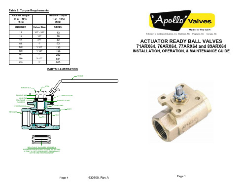
STEM BEARING
BODY
SEAT
A Division of Conbraco Industries, Inc. Matthews, NC Pageland, SC Conway, SC
ACTUATOR READY BALL VALVES
71ARX64, 76ARX64, 77ARX64 and 89ARX64
3) Install pipe plugs in the body and retainer ports of NPT valves to prevent collapsing those areas.
4) Remove the retainer from the body. It may be necessary to heat the body joint above 450°F to breakdown the sealant used to secure the valve halves.
MAINTENANCE Regular Maintenance Normal stem packing wear can be compensated for by tightening the packing gland screw. (Wrench part number H371400 is available to ease this operation.) Tighten the packing gland screw clockwise in 1/8 turn increments until observed leakage stops. Do not exceed the values shown in Table 1. If all of the adjustments to the packing gland screw have been made, remove the handle nut, handle and packing gland screw and add one or two replacements bearings on top of the old packing. Reinstall the handle and handle nut. Caution: Do not disassemble valve while under pressure nor with entrapped hazardous fluids therein.
液压机械英语

液压机械英语液压专业词汇流体传动(水力)hydraulic power液压技术(水力学)hydraulics液力技术(流体力学;水动力学)hydrodynamics 气液技术(液压气动学)hydro-pneumatics运行工况operating working conditions额定工况rated working conditions极限工况limited working conditions瞬态工况instantaneous working conditions稳态工况steady-state working conditions许用工况acceptable working conditions连续工况continuous working conditions实际工况actual working conditions效率efficiency旋转方向direction of rotation公称压力nominal pressure工作压力working pressure进口压力inlet pressure出口压力outlet pressure压降pressure drop;differential pressure背压back pressure启动压力breakout pressure充油压力charge pressure开启压力cracking pressure峰值压力peak pressure运行压力operating pressure耐压试验压力proof pressure冲击压力surge pressure静压力static pressure系统压力system pressure控制压力pilot pressure充气压力precharge pressure吸入压力suction pressure调压偏差override pressure额定压力rated pressure耗气量air consumption泄漏leakage内泄漏internal leakage外泄漏external leakage层流laminar flow紊流turbulent flow气穴(现象)cavitations流量flow rate排量displacement额定流量rated flow供给流量supply flow流量系数flow factor滞环hysterics图形符号graphical symbol液压气动元件图形符号symbols for hydraulic and pneumatic components 流体逻辑元件图形符号symbols for fluid logic devices逻辑功能图形符号symbols for logic functions回路图circuit diagram压力时间图pressure time diagram功能图function diagram循环circle自动循环automatic cycle工作循环working cycle循环速度cycling speed工步phase停止工步dwell phase工作工步working phase快进工步rapid advance phase快退工步rapid return phase频率响应frequency response重复性repeat ability复现性reproducibility漂移drift波动ripple线性度linearity线性区linear region液压锁紧hydraulic lock液压卡紧hydraulic sticking变量泵variable displacement pump泵的控制control of pump齿轮泵gear pump叶片泵vane pump柱塞泵piston pump轴向柱塞泵axial piston pump法兰安装flange mounting底座安装foot mounting液压马达(发动机,电动机)hydraulic motor刚度stiffness中位neutral position零位zero position自由位free position缸cylinder有杆端rod end无杆端rear end外伸行程extend stroke内缩行程retract stroke缓冲cushioning工作行程working stroke负载压力induced pressure输出力force实际输出力actual force单作用缸single-acting cylinder双作用缸double-acting cylinder差动缸differential cylinder伸缩缸telescopic cylinder阀valve底板sub-plate油路块manifold block板式阀sub-plate valve叠加阀sandwich(plate)valve插装阀cartridge valve滑阀slide valve锥阀poppet valve阀芯valve element阀芯位置valve element position单向阀check valve液控单向阀pilot-controlled check valve 梭阀shuttle valve压力控制阀pressure control valve溢流阀pressure relief valve顺序阀sequence valve减压阀pressure reducing valve平衡阀counterbalance valve卸荷阀unloading valve直动式directly operated type先导式pilot-operated type机械控制式mechanically controlled type 手动式manually operated type液控式hydraulic controlled type流量控制阀flow control valve固定节流阀fixed restrictive valve可调节流阀adjustable restrictive valve 单向节流阀one-way restrictive valve调速阀speed regulator valve分流阀flow divider valve集流阀flow-combining valve截止阀shutoff valve球阀global/ball valve针阀needle valve闸阀gate valve膜片阀diaphragm valve蝶阀butterfly valve噪声等级noise level放大器amplifier模拟放大器analogue amplifier数字放大器digital amplifier传感器sensor阈值threshold(开始、开端、极限) 伺服阀servo valve四通阀four-way valve喷嘴挡板nozzle flapper液压放大器hydraulic amplifier颤振dither阀极性valve polarity流量增益flow gain对称度symmetry流量极限flow limit零位内泄漏null(quiescent) leakage 遮盖lap零遮盖zero lap正遮盖over lap负遮盖under lap开口opening零偏null bias零漂null drift阀压降valve pressure drop分辨率resolution频率响应frequency response幅值比amplitude(振幅) ratio传递函数transfer function管路flow line硬管rigid tube软管flexible hose工作管路working line回油管路return line补液管路replenishing line控制管路pilot line泄油管路drain line放气管路bleed line接头fitting;connection焊接式接头welded fitting扩口式接头flared fitting快换接头quick release coupling法兰接头flange connection弯头elbow异径接头reducer fitting流道flow pass油口port闭式油箱sealed reservoir油箱容量reservoir fluid capacity气囊式蓄能器bladder accumulator空气污染air contamination固体颗粒污染solid contamination液体污染liquid contamination空气过滤器air filter油雾气lubricator热交换器heat exchanger冷却器cooler加热器heater温度控制器thermostat消声器silencer双筒过滤器duplex filter过滤器压降filter pressure drop有效过滤面积effective filtration area公称过滤精度nominal filtration rating压溃压力collapse pressure填料密封packing seal机械密封mechanical seal径向密封radial seal旋转密封rotary seal活塞密封piston seal活塞杆密封rod seal防尘圈密封wiper seal;scraper组合垫圈bonded washer复合密封件composite seal弹性密封件elastomer seal丁腈橡胶nitrile butadiene rubber;NBR聚四氟乙烯Polytetrafluoroethylene;PTFE 优先控制override control压力表pressure gauge压力传感器electrical pressure transducer压差计differential pressure instrument液位计liquid level measuring instrument流量计flow meter压力开关pressure switch脉冲发生器pulse generator液压泵站power station空气处理单元air conditioner unit压力控制回路pressure control circuit(loop)安全回路safety circuit差动回路differential circuit调速回路flow control circuit进口节流回路meter-in circuit出口节流回路meter-out circuit同步回路synchronizing circuit开式回路open circuit闭式回路closed circuit管路布置pipe-work管卡clamper联轴器drive shaft coupling操作台control console(控制台)控制屏control panel避震喉compensator粘度viscosity运动粘度kinematical viscosity密度density含水量water content闪点flash point防锈性rust protection(quality)抗腐蚀性anticorrosive quality便携式颗粒检测仪portable particle counterPilot valve 先导阀Pilot-operated check valve 液控单向阀Sub-plate mount 板式安装Manifold block 集成块Pressure relief valve 压力溢流阀Flow valve 流量阀Throttle(扼杀)valve 节流阀Double throttle check valve 双单向节流阀Rotary knob 旋钮Rectifier plate 节流板Servo valve 伺服阀Proportional valve 比例阀Position feedback 位置反馈Progressive flow 渐增流量De-energizing of solenoid(螺线管)电磁铁释放二、介质类Phosphate ester (HFD-R) 磷酸甘油酯Water-glycol (HFC) 水-乙二醇Emulsion 乳化液Inhibitor缓蚀剂Synthetic lubricating oil 合成油三、液压安装工程Contamination 污染Grout 灌浆Failure 失效Jog 点动Creep爬行Abrasion 摩擦Extension(活塞杆)伸出Retraction(活塞杆)缩回Malfunction 误动作Pickling 酸洗Flushing 冲洗Dipping process 槽式酸洗Recirculation 循环Passivity 钝化Nitric acid 柠檬酸Argon 氩气Butt welding 对接焊Socket welding 套管焊Inert gas welding 惰性气体焊四、管接头Bite type fittings卡套式管接头Tube to tube fittings 接管接头union 直通接管接头elbow union 直角管接头tee union 三通管接头cross union 四通管接头Mal stud fittings 端直通管接头Bulkhead fittings 长直通管接头Weld fittings 焊接式管接头Female connector fittings 接头螺母Reducers extenders 变径管接头Banjo fittings 铰接式管接头Adjustable fittings/swivel nut 旋转接头五、伺服阀及伺服系统性能参数Dynamic response 动态频响DDV-direct drive valve 直动式伺服阀NFPA-National Fluid Power Association 美国流体控制学会Phase lag 相位滞后Nozzle flapper valve 喷嘴挡板阀Servo-jet pilot valve 射流管阀Dither 颤振电流Coil impedance 线圈阻抗Flow saturation 流量饱和Linearity 线形度Symmetry 对称性Hysterics 滞环Threshold 灵敏度Lap 滞后Pressure gain 压力增益Null 零位Null bias 零偏Null shift 零飘Frequency response 频率响应Slope 曲线斜坡液压系统(hydraulic system)执行元件(actuator)液压缸cylinder液压马达motor液压回路circuit压力控制回路pressure control流量(速度)控制回路speed control方向控制回路directional valve control安全回路security control定位回路position control同步回路synchronizing circuit顺序动作回路sequent circuit液压泵pump阀valve压力控制阀pressure valve流量控制阀flow valve方向控制阀directional valve液压辅件accessory普通阀common valve插装阀cartridge valve叠加阀superimposed valve;Sandwich plate valve 支承环Backup ring液压专业常用英语词汇一、阀类Solenoid valve (工业)电磁阀Check valve 单向阀Cartridge valve 插装阀Pilot valve 先导阀Pilot-operated check valve 液控单向阀Sub-plate mount 板式安装Manifold block 集成块Pressure relief valve 压力溢流阀Flow valve 流量阀Throttle valve 节流阀Double throttle check valve 双单向节流阀Rotary knob 旋钮Rectifier plate 节流板Servo valve 伺服阀Proportional valve 比例阀Position feedback 位置反馈Progressive flow 渐增流量De-energizing of solenoid 电磁铁释放二、介质类Phosphate ester (HFD-R) 磷酸甘油酯Water-glycol (HFC) 水-乙二醇Emulsion 乳化液Inhibitor缓蚀剂Synthetic lubricating oil 合成油三、液压安装工程Contamination 污染Grout 灌浆Failure 失效Jog 点动Creep爬行Abrasion 摩擦Retract(活塞杆)伸出Extension (活塞杆)缩回Malfunction 误动作Pickling 酸洗Flushing 冲洗Dipping process 槽式酸洗Re-circulation 循环Passivity 钝化Nitric acid 柠檬酸Argon 氩气Butt welding 对接焊Socket welding 套管焊Inert gas welding 惰性气体焊四、管接头Bite type fittings 卡套式管接头Tube to tube fittings 接管接头union 直通接管接头union elbow 直角管接头union tee 三通管接头union cross 四通管接头Mal stud fittings 端直通管接头Bulkhead fittings 长直通管接头Weld fittings 焊接式管接头Female connector fittings 接头螺母Reducers extenders 变径管接头Banjo fittings 铰接式管接头Adjustable fittings/swivel nut 旋转接头五、伺服阀及伺服系统性能参数Dynamic response 动态频响DDV-direct drive valve 直动式伺服阀NFPA-National Fluid Power Association 美国流体控制学会Phase lag 相位滞后Nozzle flapper valve 喷嘴挡板阀Servo-jet pilot valve 射流管阀Dither 颤振电流Coil impedance 线圈阻抗Flow saturation 流量饱和Linearity 线形度Symmetry 对称性Hysterics 滞环Threshold 灵敏度Lap 滞后Pressure gain 压力增益Null 零位Null bias 零偏Null shift 零飘Frequency response 频率响应Slope 曲线斜坡泵(本)体bump body无油轴承dry bearings油封oil seal扣环retainer ring定位梢locking pin前分流板front port plate凸轮环cam ring轮子rotor后分流板rear port plateO型环O ring端盖end cover六角沉头螺丝countersink hex-crew双头活塞twin piston弹簧spring单头活塞snap piston上盖top cover调整螺栓adjustable bolt螺帽screw nut半圆键woodruff key柱塞plug screw塞头螺丝plug screw排量cc/rev最高使用压力kgf/cm²(psi) (bar) 315kgf/cm²=4500psi 转速范围rpm零件表parts list塞头plug侧盖side cover调压柱塞spool调流侧盖side cover ( deliv, vol )调压本体pressure adj. bolt高压柱塞spool调压弹簧座spring post脚座型foot type轴shaft法兰座flange (lug)键沟keyway前分流套front port block后分流套rear port block后盖rear cover尺寸图dimensions性能曲线performance curves工作压力MPa (bar) 1MPa=10.2Kgf/cm²排量cm³/rev转速范围r/min输入信号电压(DC) (V)流量Qin流量(lpm)压力Pin频率Hz接通时间单位ms线圈耗电功率(A/V A max)压力范围(Pnom.: bar)流量(Qnom.: e/min)电-液比例换向调速阀proportional electro-hydraulic directional and flow control valves额定电流rated current零值电流quiescent current过载电流overload current线圈电阻coil resistance线圈电感coil inductance额定流量rated flow流量增益flow gain内漏internal leakage非线性度nonlinearity不对称度unsymmetry重叠lap压力增益pressure gain零偏null bias分辨率threshold频率特性frequency response电插头座electrical connector颤振dither伺服放大器servo-amplifier供油压力supply pressure回油压力return pressure耐压和破坏压力proof and burst pressure工作液fluids工作液清洁度filtration液压特性hydraulic characteristics静态特性static performance极性polarity空载流量特性no-load flow characteristic负载特性flow-load characteristics动态特性dynamic performance转移函数transfer function双喷嘴-挡板力反馈两级电液流量控制的伺服阀Double flapper-nozzle, force feedback, two stage electro-hydraulic flow control servo-valves 外形图external configuration结构原理图configuration幅频宽amplitude radio width相频宽phase lag width防尘圈bust wiper; Pin bust seal耐磨环(磨损环) wear ring ; slide ring; abrasion resistant ring滑阀slide valve活塞油封piston seal活塞杆油封rod seal垫片back up ring支承环support ring缓冲环buffer seal气缸垫cylinder washer断面图形section graphics夹布橡胶inter-cloth rubber乳化液emulsion公称尺寸nominal size允差tolerance杂质impurities凹凸缺陷convex and concave disfigurement边缘痕迹edge imprint沟槽尺寸dimension of slot替代substitute取代supersede导向带guide strip挡圈retaining ring简记abridged notation风动机械pneumatic machineries格来圈Gely ring斯特封Sterfin ring聚四氟乙烯青铜复合材料compound material of PTFE and bronze 安装尺寸installation dimension导向环guiding ring聚甲醛polyoxymethylene夹布胶木inter-cloth bakelite聚氨酯板/棒Polyurethane Bar梅花型联轴器弹性圈club-type elastic ring for joint-shaft皮碗packing bowl夹织物inter-fabrics螺纹插装阀cartridge valves电磁换向阀solenoid-operated valves压力控制阀pressure control valves调压范围spring ranges方向控制阀directional control valves阀芯结构形式type of pin锥阀poppet滑阀spool球阀ball流量控制阀flow control valves控制比例pilot ratios二位二通型two way two position锁紧扭矩mounting screw torque标准插封standard cavity标准阀块standard block标准线圈外形尺寸E-Coil shape dim.直动式溢流阀directly operated relief valves差动式溢流阀differential area relief valves先导式溢流阀pilot-operated relief valves组合溢流阀combined relief valves遥控溢流阀remote control relief valves油液清洁度filtration of oil双向溢流阀bi-directional relieve valves减压阀pressure reducing valves直动式顺序阀direct-acting sequence valves管式单向阀tubular check valves技术参数technical data开启压力cracking pressure压力补偿节流阀(固定节流孔)regulator pressure-compensated valves(fixed orifice)分流/集流阀flow divider/combiner valves节流controlled flow负载控制阀load control valves插式直动/先导溢流阀relief cartridge valves型号说明ordering code插式节流单向阀needle check cartridge valves碟式充液阀flange-clamped type, prefill valves油箱侧低压配管suction side pipe导压口接头pilot port adaptor油缸侧高压配管cylinder side pipe管式压力反馈型调速阀pressure-compensated flow control valves管式压力继电器pressure switch-pipe series叠加式压力继电器pressure switch-modular series叠加式电磁调速阀flow control sandwich-valves-solenoid operated管式/板式液压升降阀hydraulic lifting/lowering control valves额定电压rated voltage额定功率nominal power额定转速rotation speed力矩torque转向rotation direction三插hirschmann带嵌套conduit德意志插座integral Deutsch connector双插double spade圆形cylindrical手动卸荷manual override丁腈橡胶NBR氢化丁腈橡胶HNBR氟橡胶FKM硅橡胶PMQ/VMQ聚丙烯酸酯橡胶ACM乙丙橡胶EPDM/EPM夹布橡胶FAB聚氨酯PU热塑型聚氨酯TPU浇注型聚氨酯CPU聚四氟乙烯PTFE聚酰胺PA聚甲醛POM轴用密封(活塞杆) rod seals孔用密封(活塞)piston seals防尘密封件scrapers阀门英语名词术语(1)范围本标准适用于工业管道(或机器、设备)的通用阀门。
欧特顿Moeller系列MSC-D直流启动器说明书

Eaton 115936Eaton Moeller® series MSC-D DOL starter, 380 V 400 V 415 V: 5.5 kW, Ir= 8 - 12 A, 24 V 50Hz/60Hz, ACGeneral specificationsEaton Moeller® series MSC-D DOL starter115936MSC-D-12-M12(24V50/60HZ)401508115676495 mm 180 mm 45 mm 0.589 kgUL60947-4-1A CSA-C22.2 No. 14-10 IEC/EN 60947-4-1 ULCSA File No.: 012528 CSA VDE 0660CSA Class No.: 3211-24 UL Category Control No.: NKJH CEUL File No.: E123500Product NameCatalog Number Model CodeEANProduct Length/Depth Product Height Product Width Product Weight Certifications12 AIs the panel builder's responsibility. The specifications for the switchgear must be observed.5.5 kW230 - 415 V AC0 A24 VMeets the product standard's requirements.Is the panel builder's responsibility. The specifications for the switchgear must be observed.DIN railDoes not apply, since the entire switchgear needs to be evaluated.0 kW0 kWMeets the product standard's requirements.0 VShort-circuit release0Simple, flexible and safe! Distribution system for motor-starter combinationsSave time and space thanks to the new link module PKZM0-XDM32ME Motor Starters in System xStart - brochureProduct Range Catalog Switching and protecting motorsDA-DC-00004878.pdfDA-DC-00004910.pdfeaton-manual-motor-starters-motorstarter-msc-d-dol-starter-dimensions.epseaton-manual-motor-starters-mounting-msc-d-dol-starter-3d-drawing.eps eaton-general-ie-ready-dilm-contactor-standards.epsDA-CE-ETN.MSC-D-12-M12(24V50_60HZ)IL034038ZUIL034014ZUWIN-WIN with push-in technologyDA-CD-msc_d_bg1DA-CS-msc_d_bg1eaton-manual-motor-starters-device-msc-d-dol-starter-wiring-diagram.epsRated operational current for specified heat dissipation (In) 10.11 Short-circuit ratingRated operational power at AC-3, 380/400 V, 50 Hz Rated operational voltageRated conditional short-circuit current, type 1, 480 Y/277 V Rated control supply voltage (Us) at AC, 50 Hz - min10.4 Clearances and creepage distances10.12 Electromagnetic compatibilityMounting method10.2.5 LiftingRated power at 575 V, 60 Hz, 3-phaseRated power at 460 V, 60 Hz, 3-phase10.2.3.1 Verification of thermal stability of enclosures Rated control supply voltage (Us) at DC - minFitted with:Number of pilot lightsRated control supply voltage (Us) at AC, 50 Hz - max BrochuresCatalogsDeclarations of conformity DrawingseCAD modelInstallation instructions Installation videosmCAD modelWiring diagrams24 VCoordination type110.8 Connections for external conductorsIs the panel builder's responsibility.Coordination class (IEC 60947-4-3)Class 1Rated conditional short-circuit current, type 1, 600 Y/347 V0 APower consumption, sealing, 50 Hz1.4 CO, Coil in a cold state and 1.0 x UsAmbient operating temperature - max55 °CRated operational power at AC-3, 220/230 V, 50 Hz3 kWConnection to SmartWire-DTNoNumber of command positionsStatic heat dissipation, non-current-dependent Pvs1.4 WElectrical connection type of main circuitScrew connectionElectrical connection type for auxiliary- and control-current circuit Screw connectionRated control supply voltage (Us) at DC - max0 V10.9.3 Impulse withstand voltageIs the panel builder's responsibility.Ambient operating temperature - min-25 °C10.6 Incorporation of switching devices and componentsDoes not apply, since the entire switchgear needs to be evaluated.10.5 Protection against electric shockDoes not apply, since the entire switchgear needs to be evaluated.ClassCLASS 10 A10.13 Mechanical functionThe device meets the requirements, provided the information in the instruction leaflet (IL) is observed.10.2.6 Mechanical impactDoes not apply, since the entire switchgear needs to be evaluated.10.9.4 Testing of enclosures made of insulating materialIs the panel builder's responsibility.10.3 Degree of protection of assembliesDoes not apply, since the entire switchgear needs to be evaluated.Heat dissipation per pole, current-dependent Pvid2.9 WActuating voltage24 V 50Hz/60HzVoltage typeACSwitching capacity (auxiliary contacts, general use)15 A, 600 V AC, (UL/CSA)1 A, 250 V DC, (UL/CSA)Overload release current setting - min8 AEquipment heat dissipation, current-dependent Pvid8.7 WHeat dissipation capacity Pdiss0 WRated operational current (Ie)11.3 ASuitable forAlso motors with efficiency class IE3Number of auxiliary contacts (normally closed contacts)Rated conditional short-circuit current (Iq), type 2, 380 V, 400 V, 415 V0 APower consumption1.4 W10.2.3.2 Verification of resistance of insulating materials to normal heatMeets the product standard's requirements.10.2.3.3 Resist. of insul. mat. to abnormal heat/fire by internal elect. effectsMeets the product standard's requirements.Overload release current setting - max12 A10.9.2 Power-frequency electric strengthIs the panel builder's responsibility.Overvoltage categoryIIIDegree of protectionIP20NEMA OtherPollution degree3Rated control supply voltage (Us) at AC, 60 Hz - min24 V10.7 Internal electrical circuits and connectionsIs the panel builder's responsibility.Rated impulse withstand voltage (Uimp)6000 V ACConnectionScrew terminals10.10 Temperature riseThe panel builder is responsible for the temperature rise calculation. Eaton will provide heat dissipation data for the devices.FunctionsTemperature compensated overload protectionRated conditional short-circuit current (Iq), type 2, 230 V0 ATypeStarter with Bi-Metal release10.2.2 Corrosion resistanceMeets the product standard's requirements.Eaton Corporation plc Eaton House30 Pembroke Road Dublin 4, Ireland © 2023 Eaton. All Rights Reserved. Eaton is a registered trademark.All other trademarks areproperty of their respectiveowners./socialmediaMeets the product standard's requirements.Meets the product standard's requirements.186 A24 V12 A Direct starter1Max. 2000 mP300, DC operated (UL/CSA) A600, AC operated (UL/CSA)10.2.4 Resistance to ultra-violet (UV) radiation 10.2.7 InscriptionsShort-circuit release (Irm) - max Rated control supply voltage (Us) at AC, 60 Hz - max Rated operational current (Ie) at AC-3, 380 V, 400 V, 415 V Model Number of auxiliary contacts (normally open contacts)Altitude Switching capacity (auxiliary contacts, pilot duty)。
欧洲之星 ZSC ZWC-安装和维护说明书 2012版

2 3
4 5
��设置 . . . . . . . . . . . . . . . . . . . . . . . . . . . . . . . . . . . . . . . 8.1 基本设置 . . . . . . . . . . . . . . . . . . . . . . . . . . . . . . . . 8.1.1 检看膨胀水箱容积 . . . . . . . . . . . . . . . . . . . . . . . . . 8.1.2 更改供暖泵特性 . . . . . . . . . . . . . . . . . . . . . . . . . . . 8.2 Heatronic 3 控制器设置 . . . . . . . . . . . . . . . . . . . . . 8.2.1 操作 Heatronic 3 控制器 . . . . . . . . . . . . . . . . . . . . 8.2.2 设备最大或最小额定功率 . . . . . . . . . . . . . . . . . . . 8.2.3 供热输出 (检修功能 1.A) . . . . . . . . . . . . . . . . . 8.2.4 热水输出 (检修功能 1.b). . . . . . . . . . . . . . . . . . 8.2.5 集中采暖泵控制模式 (检修功能 1.E) . . . . . . . 8.2.6 设备最大集中采暖出水 温度 (检修功能 2.b) . 8.2.7 高温消毒 (检修功能 2.d) (ZSC). . . . . . . . . . 8.2.8 周期锁闭 (检修功能 3.b) . . . . . . . . . . . . . . . . . 8.2.9 切换滞后 (检修功能 3.C) . . . . . . . . . . . . . . . . 8.2.10 定时器切换 (检修功能 5.C) . . . . . . 8.2.11 热水需求响应延时 (检修功能 9.E) (ZWC) . 8.2.12 显示 Heatronic 3 控制器设置 . . . . . . . . . . . . . . . . 燃气�型 �换 . . . . . . . . . . . . . . . . . . . . . . . . . . . . . . . . . . . . . . . . . . . 9.1 燃气设置 (天然气和液化气). . . . . . . . . . . . . . . 9.1.1 喷嘴压力 . . . . . . . . . . . . . . . . . . . . . . . . . . . . . . . . . 9.1.2 体积流量 . . . . . . . . . . . . . . . . . . . . . . . . . . . . . . . . .
- 1、下载文档前请自行甄别文档内容的完整性,平台不提供额外的编辑、内容补充、找答案等附加服务。
- 2、"仅部分预览"的文档,不可在线预览部分如存在完整性等问题,可反馈申请退款(可完整预览的文档不适用该条件!)。
- 3、如文档侵犯您的权益,请联系客服反馈,我们会尽快为您处理(人工客服工作时间:9:00-18:30)。
脉冲阀
尺寸
快速接头脉冲阀
AE1825R, AE1840R
AE2825R, AE2840R
AE1440R
AE2440R
型号
AE1825R0000 AE1840R0000 AE1440R0000 AE2825R0000 AE2840R0000 AE2440R0000
øA
(GAS/BSP)
1“ 1 ½” 1 ½”
1/4”
—
23,6 76,5 98
1/4”
—
23,6 76,5 98
1/4”
—
23,6 76,5 98
1/4”
—
33
98 136
1/4”
—
33
129 136
1/4”
1/8”
40
161 159
1/4”
3/8”
Autel S.r.l. – Electrical and Electronic Systems for air filtration – www.aeautel.it Via D. Bagnoli n°9, Sassuolo (MO) ITALY. Phone: +39/0536 802104 Fax: +39/0536 803372 Email: info@aeautel.it
淹没式脉冲阀
脉冲阀
阀体
喷吹管
紧固环
一般概述
淹没式脉冲阀是一系列用来安装在圆形气包上的高效脉冲阀,不需焊接即可保证快速,安全的组装。只要将配套在 阀体下方的紧固锁紧就可完成组装。如同与传统的螺纹连接式及快速接头脉冲阀一样,通电的方式由以下几种: ·直接方式:先导阀直接安装在阀体上,以线圈方式通电。 ·远程方式: 先导阀是远程的,以气动为通电方式。先导阀与阀体之间用一条rilsan管连接。 这些阀门的特点是响应时间快,换向迅速,可在短时间内形成高压脉冲气体且空气消耗降低。这是对阀门内部几何
øA
(GAS/BSP) 3/4” 3/4” 1” 1” 1 1/2” 1 1/2” 2” 3/4” 3/4” 1” 1” 1 1/2” 1 1/2” 2”
B mm
44 52 64 52 67 67 85 44 52 64 52 67 67 85
C mm
79 103 115 103 127 127 167 79 103 115 103 127 127 167
正常下闭合 -20 °C +100 °C 8 Bar 快速接头 压铸铝合金表面抛丸 铜 空气或惰性气体
Pg9 C-VDE 0110 Din 43650 – IS0 4400 IP 65 230-150-24 V /50-60 HZ AC 24 V DC 17 VA AC / 17 W DC
如何订购
AE 14 25 R 0 000
Φ 管径尺寸 1” 1½” 1½” 1” 1½” 1½”
通电方式
本体 本体 本体 远程 远程 远程
快速接头
无 无 无 有 有 有
膜片数 1 1 2 1 1 2
重量(KG) 1,00 1,80 2,24 0,80 1,60 2,04
Autel S.r.l. – Electrical and Electronic Systems for air filtration – www.aeautel.it Via D. Bagnoli n°9, Sassuolo (MO) ITALY. Phone: +39/0536 802104 Fax: +39/0536 803372 Email: info@aeautel.it
AE2440B, AE2450B
D
E
F
øL
øM
mm mm mm (GAS/BSP) (GAS/BSP)
21
118 69,3
—
—
23,6 128,5 98
—
—
23,6 128,5 98
—
—
23,6 128,5 98
—
—
33
150 136
—
—
33
181 136
—
—
40
213 159
—
—
21
66,5 69,3
脉冲阀
技术参数
产品一般参数
静止状态 启动温度 最大压力 连接方式 材质 导阀 流体
电力特性
接头 隔绝等级 特殊接头 保护等级 电压 Absorbed power
型号及规格
型号 AE1825R0000 AE1840R0000 AE1440R0000 AE2825R0000 AE2840R0000 AE2440R0000
快速接头
无 无 无 无 无 无 无 有 有 有 有 有 有 有
膜片数 1 1 1 1 1 2 2 1 1 1 1 1 2 2
重量 (KG) 0,46 0,84 0,83 0,85 1,16 1,60 2,30 0,26 0,64 0,63 0,65 0,96 1,40 2,10
Autel S.r.l. – Electrical and Electronic Systems for air filtration – www.aeautel.it Via D. Bagnoli n°9, Sassuolo (MO) ITALY. Phone: +39/0536 802104 Fax: +39/0536 803372 Email: info@aeautel.it
技术参数
产品结构
静止状态 启动温度 最大操作压力 连接方式 阀体 导阀 流体 电气规范 接头 阻隔等级 特殊接头 电压 Absorbed power
产品型号及规格
型号 AE1818B0000 AE1820B0000 AE1825B0000 AE1825B1000 AE1840B0000 AE1440B0000 AE1450B0000 AE2818B0000 AE2820B0000 AE2825B0000 AE2825B1000 AE2840B0000 AE2440B0000 AE2450B0000
脉冲阀
Autel S.r.l. – Electrical and Electronic Systems for air filtration – www.aeautel.it Via D. Bagnoli n°9, Sassuolo (MO) ITALY. Phone: +39/0536 802104 Fax: +39/0536 803372 Email: info@aeautel.it
正常下闭合 -20 °C +100 °C 8 Bar
瓦斯规格缧纹 压铸铝合金表面抛丸 铜 空气或隋性气体
Pg9 IP 65 C-VDE 0110 Din 43650 – IS0 4400 230-150-24 V / 50-60 HZ AC 24 V DC 17 VA AC / 17 W DC
Φ 管径尺寸
1” 1 ½” 1 ½”
B
C
D
mm
mm
mm
80,5
131,5
66,5
109
1Байду номын сангаас9
71,5
109
169
71,5
80,5
131,5
66,5
109
169
71,5
109
169
71,5
E
F
øL
øM
mm mm (GAS/BSP) (GAS/BSP)
171
98
—
—
188
136
—
—
222
136
—
—
119
98
1/4”
Autel S.r.l. – Electrical and Electronic Systems for air filtration – www.aeautel.it Via D. Bagnoli n°9, Sassuolo (MO) ITALY. Phone: +39/0536 802104 Fax: +39/0536 803372 Email: info@aeautel.it
特性和深入研究而获得。如此可以保证膜片在脉冲阀的正常运转下确保超过一百万次的寿命
产品型号及规格
技术参数 静止状态 最高温度 最大压力 螺丝材质 材料 先导阀 紧固方式 流体 电器规格 接头 隔绝等级 特殊接头 保护等级 电压 Absorbed Power
正常下闭合 110 °C 8 Bar 钢 压铸铝表面抛丸 铜 锁紧阀体下方的紧固环 空气或惰性气体
Autel
1: 本体导阀 2: 远程导阀
0:标准 1:短距
8: 单膜片 4: 双膜片
Φ in/out 管径尺寸 25: 1” 40: 1½ “
连接方式:
R: 快速接头
线圈电压 020:DC24V 025:AC24V/50Hz,
AC26V/60Hz 115:AC 150V/50H 60Hz 225:AC 230V/50Hz 60Hz
3/4“ 3/4” 1” 1” 1½” 1½” 2” 3/4“ 3/4” 1” 1” 1½” 1½” 2”
导阀
本体 本体 本体 本体 本体 本体 本体 远程 远程 远程 远程 远程 远程 远程
如何订购
AE 14 25 B 0 000
Autel
1: 本体导阀 2: 远程导阀
0: 标准 1: 短距
连接方式 :
—
136
136
1/4”
—
170
136
—
1/8”
Autel S.r.l. – Electrical and Electronic Systems for air filtration – www.aeautel.it Via D. Bagnoli n°9, Sassuolo (MO) ITALY. Phone: +39/0536 802104 Fax: +39/0536 803372 Email: info@aeautel.it