派克TTF系列过滤器中文样本
高效压缩空气过滤器Parker说明书

●Atmospheric Dirt ●Rust ●pipescale●Water Vapour ●Condensed Water ●Water Aerosols●Liquid Oil ●Oil Aerosols ●Oil Vapour●Micro – organismsCompressed air is an important source of energy in today’s modern production factories because it isflexible and reliable.1[[Contaminants are ever present in the atmosphere. The compressed air stream typically contains water, oil, dirt and micro-organisms which can contribute to product rejects, lost production time and increased maintenance expenses. For example, small traces of impurities can cause serious sheye blemishing in automotive nishing operations. Water left in air stream can freeze during exposure to cold temperatures, blocking ow or rupturing pipes. Residual compressor oil and water can form an acidic sludge and therefore, compressed air contaminants will eventually, lead to premature component wear, needing repairs or replacements.Most problems experienced by compressed air users derive from contamination that already in the compressed air system.There are typically 10 different contaminants. These are coming from four different sources:Before compressed air can be ef ciently used, these contaminants need to be removed orreduced to acceptable levels.Parker EcoPure Plus compressed air filter● Air flow from 0.6m 3/min to 40m 3/min ●Filter housings from 1/4” BSPP to 3” BSPP connections● Operate at pressures from 1 bar g to 16 bar g ● Technically advanced and proven technology ●Patented, unique element interface for high efficiency filter performance● Filter element performance guaranteed for 12 months * ●Air quality performance tested in accordance with ISO8573* - If used in accordance with manufacturer’s instructionsParker Hanni n, the global leader in motion and control technologies, carries a stable of strong known brands in the eld of compressed air treatment. Parker EcoPure Plus is our latest addition to this family and continues to offer a perfect high value solution to compressed air puri cation.The Parker EcoPure Plus range lter is designed by Parker’s highly trained team of lter experts with advanced and proven compressed air puri cation technology. It combines the key essential elements of Parker’s total ltration knowledge, pooled over decades of lter manufacturing experience to ensure clean compressed air with the minimum of cost.2Compressed air is expensive to produce and must be properly treated in order to limit maintenance costs,downtime and spoilage.[[3Filter PerformanceParker EcoPure Plus - Embodying the The Parker EcoPure Plus series of compressed air lters, inherits many characteristics of Parker’s compressed air ltration technology. Yes, this is Parker EcoPure Plus - an innovation in compressed air ltration, designed with reliability & ef ciency for you.Parker EcoPure Plus amasses decades of Parker's design experience in compressed air lters, drawing out the most perfect high value solution to compressed air puri cation. Most importantly, Parker EcoPure Plus delivers consistent high quality compressed air.In a comparative test of Parker EcoPure Plus lters against ve commonly available alternative lters, the blockage characteristics and the true differential pressure of each lter re ects its superior performance.Essence of Compressed Air Filters4Proven technology means Reliability & EfficiencyMaintaining air quality and energy efficiency through regular maintenanceParker EcoPure Plus lters carry air ow from the inside out; a long understood and proven method. Liquid contaminants are captured in the lter matrix and collect together into larger and larger droplets through collisions with the media. These droplets eventually coalesce on the outside of the lter tube where they collect and are drained away by gravity.The inner element surface acts as a pre- lter to remove large contaminants while the internal pores are trap and to remove aerosols and solids from the air stream. The larger outside pores also allow a smooth air stream to pass freely through the media, minimizing pressure drop.Another important relationship is the gap between the lter element outside diameter and the lter bowl's inner diameter. The spacing between these two surfaces are sized so that air velocity is minimized, thus reducing the possibility of oil or water vapor carryover.It has long been the practice to change lter elements based upon the pressure drop measured across the lter as this directly contributes to increased operational costs. However, one must remember the reason for installing the lter in the rst place, i.e. to achieve high quality compressed air.Filter elements must always be replaced in accordance with the manufacturers instructions to ensure the delivered air quality is never compromised.Parker EcoPure Plus- Feature The zero-loss drain (standard forltration grades GP & HE) features an auto-cleaning protection screen for highest reliability. Simply press the drain to verify its correct operation.As the clean air exits the element, outlet air stabilizers direct the air out of the lter housing with the minimum of turbulence andpressure loss. These also ensure the element is located correctly within the lter bowl.The differential pressureindicator gives a visualindication on the current state of the lter element.(option)To maintain your guaranteed air quality, lter elements must be replaced every year with genuine Parker parts. Throughout its life, the lter element is constantly under bombardment from oily, acidic condensate and high velocity dirt particles, which needs to be removed and retained to protect your compressed air system.5Surface ProtectionAll sizes of housings are built to the highest quality standards, featuring our unique surface protectiontreatment, applied to both the inside and the outside of the lter housing. Thanks to the attention of quality surface treatment, Parker EcoPure Plus can withstand even the toughest industrial conditions and comes with a 5 year guarantee on the lter housings.Filtration MediaModern coalescing lters use a graded porosity lter medium with ne glass bers in the interior and larger bers on both the inside and outside surfaces. Parker EcoPure Plus elements have 8 to 10μm pores on the inner surface, reducing to 0.5 μm pores in the interior of the element, and widening to 40 to 80μm pores on the outer surface.Coalescing ElementsThis coalescing element is made with Parker’s special UNI-CAST construction. Composing an epoxy saturated, borosilicate glass micro- ber media, this media is used in applications requiring the removal of liquid and particulate contamination. The outer synthetic fabric layer allows swift removal of coalesced liquids.6minimum clearanceCompressed Air Standards and ApplicationsFrom aeration in pharmaceutical and chemical processes to pneumatic power systems, the possibilities for applications are endless. Parker has some suggested air cleanliness standards that may fit your needs.International Standard ISO8573-1 has become the industry standard method for specifying compressed air cleanliness. The following diagrams describe various systems in terms of their corresponding ISO classification.The applications are based upon the test result of GP-060-FX, HE-060-FX and AC-060-MX.Product SelectionStated flows are for operation at 7 bar g (100 psi g) with reference to 20°C, 1 bar a, 0% relative water vapour pressure.For flows at other pressures apply the correction factors shown.Correction FactorsFilter Coding ExamplesTo correctly select a filter model, the flow rate of the filter must be adjusted for the minimum operating pressure of the system 1. Obtain the minimum operating pressure and maximum compressed air flow rate at the inlet of the filter.2. Select the correction factor for minimum operating pressure from the CFP table (always round down e.g. for 5.3 bar, use 5 bar correction factor)3. Calculate the minimum filtration capacity Minimum Filtration Capacity = Compressed Air Flow Rate x CFP4. Using the minimum filtration capacity, select a filter model from the flow rate tables above (filter selected must have a flow rate equal to or greater than the minimum filtration capacity)Filtration GradesGrade GP filters are used as pre-filters for Grade HE to remove gross amounts ofparticle, water and oil aerosols.Grade GPGrade HEGrade ACAdsorption Element(removal of vapor and odor)9(Precede with Grade GP filter) Grade HE filters are used when “total removal of particle, water and oil aerosols” is required. Because of its overall performancecharacteristics, this grade is most often recommended.(Precede with Grade HE filter) Grade AC are used to remove oil vapor and odor. It is used to remove smell or taste ofcompressor lube oil, as well as trace amounts of oil vapour in the compressed air stream.Weights and DimensionsAccessories1. Tested per ISO 8573.2.2. Oil vapor removal efficiency is given for AC media.Differential Pressure Gauge Float Drain Manual Drain10Europe domnick hunter IndustrialDukesway, Team Valley Trading Estate Gateshead, Tyne & Wear England NE11 0PZT +44 (0) 191 402 9000, F +44 (0) 191 482 Compressed Air TreatmentParker Gas SeparationsOude Kerkstraat 4P O Box 2584870 AG Etten-Leur, NetherlandsT +31 76 508 5300, F +31 76 508 5333Hiross ZanderPadova Business UnitStrada Zona Industriale 435020 S. Angelo di Piove Padova, Italy T +39 049 9712 111, F +39 049 9701 Hiross ZanderEssen Business UnitZander Aufberaitungstechnik GmbH Im Teelbruch 118D-45219 Essen, GermanyT +49 2054 9340, F +49 2054 934164www.zander.deRacorShaw Cross Business Park Churwel Vale Dewsbury,WF12 7RD England T +44 (0) 1924 487000, F +44 (0) 1924 /rfdeRacor Research & DevelopmentParker Hannifin GmbH & Co KG Inselstrasse 3-570327 Stuttgart Germany T +49 (0) 711 7071 290-0, F +49 (0) 711 7071 /racorHydraulic FilterStieltjesweg 8, 6827 BV P.O. Box 5008 6802 EA Arnhem, HollandT +31 26 3760376, F +31 26 /hfdeUrjala OperationSalmentie 26031700 Urjala as FinlandT +358 20 753 2500, F +358 20 753 /hfdeCondition Monitoring CenterBrunel Way Thetford,Norfolk IP 24 1HP EnglandT +44 1842 763299, F +44 1842 /hfdedomnick hunter ProcessDurham Road, Birtley Co. Durham,DH3 2SF EnglandT +44 (0) 191 410 5121, F +44 (0) 191 410 Engine Filtration & Water PurificationHydraulic FiltrationProcess FiltrationNorth AmericaW o r l d w i d e M a n u f a c t u r i n g L o c a t i o n sParker Hannifin Filtration Products and Systems (Shanghai) Co.,LtdNo.2 Workshop,786 Wangqiao Road,Jinqiao Processing Southem Zone,Shanghai, ChinaTel: +(86)21 5838 3030Fax:+(86)21 5838 2428Parker Hannifin Corporation Filtration GroupGlobal Headquarters 6035 Parkland Boulevard Cleveland, OH 44124-4141T 216 896 3000, F 216 896 Engine Filtration &Water PurificationRacor - Village Marine Tec.2000 West 135th Street Gardena, CA 90249T 310 516 9911, F 310 538 Hydraulic FiltrationHydraulic Filter16810 Fulton County Road #2Metamora, OH 43540-9714T 419 644 4311, F 419 644 /hydraulicfilterProcess FiltrationProcess Advanced Filtration2340, Eastman Avenue Oxnard, CA 93030T 805 604 3400, F 805 604 /processfiltrationFiltration & Separation/Balston242 Neck RoadHaverhill, MA 01835-0723T 978 858 0505, F 978 858 /balston Filtration & Separation/Finite500 Glaspie Street, PO. Box 599Oxford, MI 48371-5132T 248 628 6400, F 248 628 /finitefilterPurification, Dehydration and Filtration Division4087 Walden Avenue Lancaster, NY 14086T 716 685 4040, F 716 685 /pdfSales Office5900-B Northwoods Parkway Charlotte, NC 28269T 704 921 9303, F 704 921 Racor3400 Finch Road, PO Box 3208Modesto, CA 95353T 209 521 7860, F 209 529 /racorChina280 YunQiao RoadJinQiao Export Processing Zone Shanghai 101206 ChinaT +86 21 5031 2525, F +86 21 5834 /chinaIndiaPlot EL 26, MIDC, TTC Industrial Area Mahape, Navi Mumbai 400 709 India T +91 22 5613 7081, 82, 83, 84, 85F +91 22 2768 6618 /indiaJapan626, Totsuka-cho, Totsuka-ku Yokohama-shi, 244-0003 JapanT +81 45 870 1522, F +81 45 864 /japanKorea1-C Block, Industrial Complex of Jangan,615-1, Geumui-Ri Jangan-Myeon,Hwaseong-City Gyeonggi-Do, Korea T +82 31 359 0771, F +82 31 359 /koreaSingapore11, Fourth Chin Bee Road Singapore 619 702T +65 6887 6300, F +65 6261 /singaporeThailand1023 3rd Floor, TPS Building Pattanakam Road, Suanluang,Bangkok 10250 ThailandT +66 2717 8140, F +66 2717 /thailandLatin AmericaAfricaParker Comercio Ltda.Filtration DivisionEstrada Municipal Joel de Paula 900 Eugenio de Melo,Sao Jose dos Campos CEP 12225-390 SP BrazilT +55 12 4009 3500, F +55 12 4009 /brPan American Division-Miami7400 NW 19th Street, Suite A Miami, FL 33128T 305 470 8800, F 305 470 /panamParker Hannifin Africa Pty LtdParker Place, 10 Berne Avenue,Aeroport Kempton Park,1620 South AfricaT +27 11 9610700, F +27 11 /euAsia PacificAustralia9 Carrington Road, Castle Hill NSW 2154, AustraliaT +61 2 9634 777, F +61 2 9899 /australiaCompressed Air TreatmentFC-2-54A 12/03。
Parker Hannifin 有限公司 Finite 过滤器操作指南说明书

Instrumentation and Gas Sampling FiltersBulletin 1300 - 694/USA Finite®Stainless steel, aluminum & plastic housings Clear bowls availableConnections from 1/8” to 2” NPTPressures to 5000 PSIG••••1. Evaluate the requirements of your application. The sketches on page 49 depict popular Examples of gas sampling, process filtration, instrument air and breathing air applications.2. What type of filtration is needed? (See pages 50-51) Coalescing filter medias remove solid and liquidcontaminants from gas streams. Particulate filter media removes solids from gas streams. Adsorber media removes hydrocarbon vapors from gas streams.3. Are you searching for a specific micron rating ... or efficiency rating? If so, page 51 provides a complete breakdown of Finite ’s filter media grades and their performance specifications.4. What are the operating conditions of your application? Key criteria to consider: flow, pressure, materials of construction ... stainless steel, nylon, aluminum, etc. Pages 52-58 provide detailed descriptions of the various products available.5. Sizing - The flow chart on pages 59-60 lists the flow rates (SCFM) at various operating pressures.Filters are available with flows up to 3366 SCFM and pressure ratings up to 5000 PSIG.Finite ®Instrumentation and Gas Sampling FiltersThe following steps will help you to choose the correct filter for your application. If there are other factors involved or if you have special requirements, call Finite ’s technical support.Finite ’s instrumentation and point-of-use product line offers compressed air/gas filtration solutions for food processing, medical, chemical processing, and compressed natural gas applications. Typicalinstallations includecontaminant removal for breathing air, protection of gas analyzers and prefilters for instrument air dryers.Our UNI-CAST element technology allows us tovacuum form high-efficiency particulate and coalescing filter elements. Our elements are designed with high voidvolumes to provide longer element life while yielding lower pressure drops.Made directly from the highest quality microglass fibers available, Finite ’selements are constructed in 5 porosity grades and 9 media types to meet nearly all compressed air/gas applications.Finite ’s instrumentation filter housings are carefully engineered to meet critical application specifications. A complete line of stainless steel housings are available with a variety of pressure ratingsand flows for corrosive applications.Combination aluminumhead/nylon bowl assemblies are offered for lower operating pressures and temperatures, while disposable plastic in-lines are offered for low flow and OEM applications. If you have a specific need or are unable to find the compressed air/gas filter your application requires, call us!Let one of Finite ’sapplication engineers assist you! Visit us on the web at /finitefilter or call us toll-free1-800-521-4357 and ask for technical support.Instrumentation and steam filterFinite ®Instrumentation ApplicationsMedia Grades:Grade 6 filter elements are used when “total removal of liquid aerosols and suspended fines” is required. Because of its overall performance characteristics, this grade is most often recommended below 500 PSIG.Grade 4 filter elements are very high efficiency coalescers; for elevated pressures or lighter weight gases. Recommended when system pressure exceeds 500 PSIG.Grade 7CVP filter elements are made with two layers. The inner layer (left) effectively traps dirt particles, protecting and extending the life of the outer layer. The coalescing outer layer (right) consists of a dense matrix of glass fibers, providing highly efficient aerosol removal.Grade 10 filters are used as prefilters for grade 6 to remove gross amounts of aerosols or tenacious aerosols which are difficult to drain. This grade is often used as a ‘coarse’ coalescer.Grade 8 filter elements provide high efficiency filtration in combination with high flow rate and long element life.Grade 4Grade 6500X500XGrade 7CVP Grade 8Grade 10500X500X500XGrade 3P125X125X Three micron pleatedcellulose filters areG T FG T F HCR46810Media Grade A = Aluminum IL15 = 1/8” NPT 1= 1/4” NPTMedia Type S = 316 Stainless SteelApplication: Finite ’s high pressure filters are available with housings made of 316 stainless steel (S5R,S1R) or aluminum (A5R, A1R). This series is used for gas bypass sampling, high pressure compressed natural gas filtration, and applications with elevated pressures and corrosion resistance requirements. High efficiency particulate and coalescing elements are available with these units. Includes drain port with plug. Connection size of drain port matches inlet and outlet connection size.specifications:Application: The S1IL filter is typically applied for the particulate filtration of bottled gas or as a last chance filter where there is limited space availability. It does not have a drain port and should only be used when little or no liquid contaminant is expected.How to Order:Materials Port Size 04-023For Example: S1R-6C04-023 for complete assembly, including element. S1R X 1 for an empty housing.Media Type Media Grade 4681004-013How to Order:For Example: S1IL-8T04-013 for complete assembly, including element. S1IL X 1 for an empty housing.Element SizeElement SizeSInstrumentation and steam filterG T F HS = Short L = LongS = Short L = LongG T F Hspecifications:Application: These filters are used for gas analyzer protection andcorrosive applications where element visibility is required. These housings have smaller internal volumes which allow for quicker evacuation and fastersampling times. Includes 1/4” NPT drain port with plug.MediaType Media Grade 46810How to Order:Port Size 10-070 = longFor Example: S1PL-10T10-070 for complete assembly, including element. S1PL X 1 for an empty housing.Bowl Length Element Size10-025 = short bowl 1 = 1/4” NPT 2 = 1/2” NPTApplication: These filters have similar applications as filter above, however this version has a stainless steel bowl which allows for higher pressure and temperature applications. Includes 1/4” NPT drain port with plug.1 = 1/4” NPT 2 = 1/2” NPTMedia Type Media Grade 46810How to Order:Port Size 10-070 = longFor Example: S2SS-10G10-025 for complete assembly, including element. S2SS X 1 for an empty housing.Bowl Length Element Size10-025 = short bowl SSPSApplication: Finite ’s 2” NPT stainless steel filter is theright solution for most critical or corrosive compressed air/gas applications. Its 500 PSIG design pressure makes this an ideal choice for higher pressure applications. Bulk liquid separating,coalescing, particulate and adsorptive filters are available. Includes 1/4” NPT drain port with plug. Application: Finite ’s S3C and S4C units are economical stainless steel filter assemblies for applications in food processing, pharma -ceutical, and chemical manufacturing. Coalescing, particulate andadsorptive filters are available. Includes 1/4” NPT drain port with plug.specifications:S3C - 4.28”/108.71 mmS4C - 4.44”/112.78 mmHow to Order:For Example: SN8S X 1Elements sold separately: *CU, 3PU, AU, 7CVP and 100WS (Bulk Liquid Separator) Element size is 24-187. * insert grade: 4, 6, 8, 10Media Gradeblank for 3PU, AU 46810CU 3PU AUHow to Order:Port Size For Example: S3C-6CU13-087 for complete assembly, including element. S3C X 1 for an empty housing.Media Type 3 = 3/4” NPT 4 = 1” NPT13-087For Example: 6CU24-187 X 1Element SizeSCSN8S1XInstrumentation and steam filterMedia Gradeblank for AM 46810HMAMMedia Type 5 = 1/8” NPT 1 = 1/4” NPT06-013Port Size Application: The Q1S, Q5S series filters are an excellent choice forinstrumentation and point-of-use general air system filtration. They also provide coalescing and adsorption filtration for robotic and OEM machine manufacturers. Amanual twist drain is standard. An auto drain option is available.Application: These aluminum filters are an excellent choice for instrumentation and point-of-use general air system filtration. The zinc bowl is preferred inhigher temperature and pressure applications. They also provide coalescing and adsorption filtration for robotic and OEM machine manufacturers. A manual twist drain is standard. An auto drain option is available. How to Order:For Example: Q1S-AM06-013 for complete assembly, including element.Q1S X 1 for an empty housing.How to Order:For Example: H5S-6HM06-013 for complete assembly, including element.H5S X 1 for an empty housing.specifications:Element Sizeblank for manual twist drainA = Auto DrainF = 1/8” ID Hose Barb V = Needle ValveDrain OptionPort Size Element SizeMedia Gradeblank for AM 46810HMAMMedia Type 5 = 1/8” NPT 1 = 1/4” NPT06-013blank for manual twist drainA = Auto DrainF = 1/8” ID Hose Barb V = Needle ValveDrain OptionQSHSGT F H C CU QU 3PU AUG T F H C75PApplication: KN1S and KN5S filters are an economical way to providehigh-efficiency filtration for protection of emission analyzers, air-logic systems and low-flow point-of-use pneumatic components. Includes manual, tee-valve drain. (1/8” NPT port)114.3 mmApplication: The P1N offers economical high efficiencyfiltration for point-of-use, instrument systems or OEM circuit protection. The P1N is also used when sump and element visibility are required. Includes manual twist drain. Media Gradeblank for 75P 46810How to Order:For Example: KN1S-6C06-016 for complete assembly, including element. KN1S X 1 for an empty housing.Media Type 5 = 1/8” NPT 1 = 1/4” NPT06-016Port Size MediaGradeLeave blank for 3PU and AU46810How to Order:For Example: P1N-4QU10-025 for complete assembly, including element. P1N X 1 for an empty housing.Media Type 10-025specifications:Element Size Element SizeNote: The 75P Media Type is a 75 micron plastic filter element.PN1KN1Instrumentation and steam filterG T F Hblank forno drain; closed D = Open;constant bleed drainV = Valved;manual drainG T F H C CU QU3PUAUApplication: The ILN, IKN in-lines are used for low flow circuit protection on sensing instruments, analyzers, air-logic, and other control devices.High-efficiency coalescing and particulate elements are available. Drain types available include manual push, constant bleed or no drain.The design: This twist-lock plastic housing is designed for 50 PSIG Maximum operating pressure. The two-stage filter design allows for high efficiency ele -ment replacement and the reuse of the 74 micron prefilter (74P05-011 X 10).Application: The QN series is an excellent point-of-use filter when element visibility is required. Coalescing, particulate and adsorption elements available. Includes plastic manual twist drain.specifications:Media Gradeblank for 3PU, AU 46810How to Order:For Example: Q N15N-10QUN for complete assembly, including element. QN15NN X 1 for an empty housing.Media Type 1 = 1/4” NPT 15 = 3/8” NPT 2 = 1/2” NPTPort Size AccessoriesN = NoneD = Differential Pressure Indicator G = Differential Pressure GaugeMedia Grade 46810How to Order:For Example: IKND-4G05-011 for complete assembly, including element. IKND X 1 for an empty housing.Media Type L = 1/8” NPT K = 1/8” NPT with brass inserts05-011Port Size Type of Drain Element SizeNote: Although the element size is not included in the part number construction for this filter, the size, 10-025, is needed to order replacement elements. For Example, 6C10-025 X 8.QNNINMedia TypeAvailable for ID only44P = 44 micron SS mesh Available for MD only 5P = 5 micron SS mesh Available for ID/MD G = Epoxy T = PTFEF = FluorocarbonAvailable for SD only A = Activated Carbon J = Silica GelM = Molecular Sieve O = Oil Activated Dye4A = 1/8” Right Angle BarbsApplication: These high-efficiency, disposable in-line filters are great for analyzer and sensor protection, gas sampling, micro-system operation and robot and animation air preparation. This clear, nylon housing allows visible inspection of collected particulate. The full length internal tube support gives higher strength, even with system upsets.The Type ID enclosure in conjunction with a ‘G’, ‘T’ , ‘F’ or ‘44P’ series element is designed toprovide the most reliable, long lived, instrument air source, sensor protection, sample cleansing and purification available today. The center core provides stable backup support, reduces internal (tare) volume, centers the tube in the housing and distributes the contaminant load along the tube’s entire length. Elements in the housing are sealed by a positive serrated arrangement with built-in redundancy, ultrasonically welded.The Type MD housing in conjunction with a ‘G’, ‘T’, ‘F’ or ‘5P’ element is designed to provide a high reliability instrument air source or sensor protection where some levels of condensed moisture or oil are present. A stand-pipe is molded into the lower housing to allow for a dry exit chamber as liquids collect at the tube base. Up to 3cc of liquid can be stored in this manner. The same tube size is employed as in the Type ID. Typical applications involve high condensate conditions such as vacuum or highertemperature systems.Type MD In-line filtersFor critical point-of-use, vapor free instrument or medical systems the Type SD provides Maximum activated surface exposure to the process gas while pre-filtering with grade 10 pads and preventing media migration with exit safety filters.Adsorbing Media AvailableType A: Activated carbon for general use oil vapor removal.Type J: Silica gel moisture trap dries gas, turns white when expended.Type M: 13X molecular sieve for selective polishing and ‘last trace’ light hydrocarbon vapor removal.Type O: Activated dye turns red when exposed to oil in system.Type SD In-line filters4S = 1/8” Straight Barbsspecifications:How to Order:For Example: IDN-6G for complete assembly, including element.Type Tang LengthN = LongS = ShortEndConnectionsblank = Standard Tangs (1/4” outer diameter) 4S = 1/8” Straight Barbs 4A = 1/8” Right Angle BarbsType ID In-line filtersMedia GradeLeave blank for SD,5P,44P 46810Standard 1/4” O.D. Tangs ID MD SDInstrumentation and steam filter。
Parker Hannifin 微型空气过滤器 PF504 产品选择手册说明书

Ordering InformationBOLD ITEMS ARE MOST POPULAR.AutomaticDrainManualDrainPF504 Series1/4 Inch PortsCatalog 0700P-EMiniature PF504 SeriesPF504 FilterDimensionsA1.56(40)C0.31(8)D3.69(94)E4.00(102)F1.58(40)inches(mm)Standard part numbers shown bold.For other models refer to ordering information below.SCFM = Standard cubic feet per minute at 90 PSIG inlet and 5 PSIGpressure drop.PortSizeNPT BSPPManual Twist Drain Manual Twist Drain1/4"PF504-02DHSS PF504G02DHSSFeatures• Stainless steel construction handlesmost corrosive environments.• Fluorocarbon seals standard.• Meets NACE specificationsMR-01-75/ISO 15156.• 1/8" female threaded drain.• High Flow: 1/4" - 23 SCFM§Port Type- NPTG BSPPPort Size02 1/4 InchBowlD Metal BowlwithoutSight GaugeElementH 20 MicronG 5 MicronMaterialSS Stainless SteelPF504 - 02 D H SSOptionsBlank ManualTwist DrainR AutomaticPulse DrainFlow - dm /sP r e s s u r e D r o p - b a r3nPrimary Pressure - PSIG1.7 bar3.4 bar 5.2 bar 6.9 bar Primary Pressure - barPF504 Series Air Line FiltersCatalog 0700P-E Technical Specifications – PF504PF504 Filter Kits & AccessoriesDrain Kits –Automatic Pulse Drain ................................................RK504SY -SS Manual Twist Drain–Small (Old) ..........................................................SA600Y7-1SS Large (New) ...............................................................SAP05481Filter Element Kits –Particulate (5 Micron) .......................................................EK504VY Particulate (20 Micron) .......................................................EK504Y Pipe Nipple –1/4" 316 Stainless Steel ................................................616Y28-SSSpecificationsBowl Capacity ..................................................................1.0 Ounces Filter Rating ........................................................................20 Micron Sump Capacity ..................................................................0.4 Ounce Port Threads ..........................................................................1/4 InchPressure & Temperature Ratings –Manual T wist Drain ............................0 to 300 PSIG (0 to 20.7 bar) 0°F to 180°F (-18°C to 82°C) Auto Pulse Drain ..................................10 to 175 PSIG (0 to 12 bar) 32°F to 150°F (0°C to 66°C)Note: Air must be dry enough to avoid ice formation attemperatures below 32°F (0°C)Weight........................................................................0.6 lb. (0.27 kg)Materials of ConstructionBody .....................................................................316 Stainless Steel Bowls ...................................................................316 Stainless Steel Deflector ..................................................................................Acetal Drain ....................................................................316 Stainless Steel Element Holder .......................................................................Acetal Filter Element ................................................................Polyethylene Seals .............................................................................FluorocarbonOperationFirst Stage Filtration:Air enters at inlet port and flows through deflector plate (A) which causes a swirling action. Liquids and coarse particles are forced to the bowl interior wall (B) by the centrifugalaction of the swirling air. They are then carried down the bowl wall by the force of gravity. The baffle (D) separates the lower portion of the bowl into a “quiet zone” (E) where the removed liquid and particles collect, unaffected by the swirling air, and are therefore not reentrained into the flowing air.Second Stage Filtration:After liquids and large particles are removed in the first stages of filtration, the air flows through element (C) where smaller particles are filtered out. The filtered air then passes downstream. Collected liquids and particles in the “quiet zone” (E) should be drained before their level reaches a height where they would be reentrained in the flowing air. This can be accomplished by unscrewing the drain valve (F) slightly until the liquid begins to drain.Technical InformationE F(Revised 11-21-12)。
Parker Hannifin P33 Series标准粒子过滤器说明书
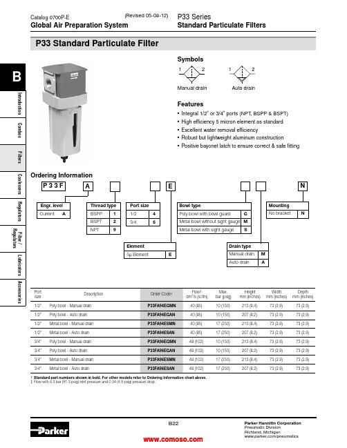
Standard Filtration
5 Micron
Useful Retention†
85 cm3 (2.8 US oz.)
Port Size
BSPP / BSPT / NPT
1/2, 3/4
Weight
0.46 kg (1.01 lbs)
* Inlet pressure 6.3 bar (91.3 psig). Pressure drop 0.34 bar (4.9 psig). † Useful retention refers to volume below the quiet zone baffle.
Filters
Combos Introduction
B
Dimensions
mm (inches)
73 (2.9)
36 (1.4)
73 (2.9)
Repair and Service Kits
Plastic bowl / Bowl guard manual drain Metal bowl / Sight gauge manual drain
Operating
Plastic Bowl -25°C to 52°C (-13°F to 125°F)
Temperature Metal Bowl -25°C to 65.5°C (-13°F to 150°F)
Max. Supply Plastic Bowl
Pressure
Metal Bowl
10 bar (150 psig) 17 bar (250 psig)
73 (2.9)
207 (8.2)
73 (2.9)
73 (2.9)
B22
派克液压中文样本

液压注意 – 用户方责任 错误或不当地选择或使用本样本或有关资料阐述的产品,可能会导致人生伤亡及财产损失! 本样本以及其它由派克汉尼汾公司及其子公司、销售公司与授权分销商所提供的资料,仅供用户专业技术人员在对产品和系统的选型进行深入调查考证时参考。
用户应全面分析自身设备的运行工况、适用的工业标准,并仔细查阅现行的样本,以详细地了解产品及系统的相关信息,通过自己的分析和试验,对产品及系统的独立的最终选择负责,确保能满足自身设备的所有性能、耐用性、维修型、安全性以及预警功能等要求。
对于派克或其子公司或授权分销商而言,应负责按用户提供的技术资料和规范,选择和提供适当的元件或系统,而用户则应负责确定这些技术资料和规范对其设备的所有运行工况和能合理预见的使用工况是否充分和准确。
目录目录页次概述 1 订货代号 2 技术参数 4 变量控制器 5 控制选项 “C”, 压力限定(恒压)变量控制器 5 控制选项 “L”, 负载传感及压力限定变量控制器 6 控制选项 “AM”, 带遥控口的标准型先导式压力限定变量控制器 7 控制选项 “AN”, 带ISO 4401 NG06先导阀安装界面的先导式压力限定变量控制器 8 控制选项 “AE”及“AF”, 带电磁比例调节的先导式压力限定变量控制器 9 控制选项 “AMT”, “ALT”及“LOT”, 带最高压力限定的扭矩限定(恒功率)变量控制器 10 P1性能特性 11典型流量特性 11 典型总效率特性 13 典型轴输入功率特性 15 典型噪声特性 18 典型轴承寿命 20 PD性能特性 22典型流量特性 22 典型总效率特性 24 典型轴输入功率特性 26 典型噪声特性 29 典型轴承寿命 31 安装尺寸 33 P1/PD 018 33 P1/PD 028 36 P1/PD 045 40 P1/PD 060 44 P1/PD 075 49 P1/PD 100 54 P1/PD 140 59 变量控制器安装尺寸 65 可提供的扩展的液压产品 75派克汉尼汾备记派克汉尼汾概述简介, 优点派克汉尼汾简介 • 开式回路用轴向柱塞式变量液压泵 • 中压,连续工作压力280 bar • 高驱动转速型,适用于行走机械; 低噪声型,适用于工业应用 • 静音及高效的控制效能 优点 • 总结构尺寸紧凑 • 低噪声• 流量脉动小,进一步降低噪声• 采用弹性密封,不使用密封垫,从而避免外泄漏的产生• 总效率高,功耗小,减小发热• 采用带无泄漏调节装的简单变量控制器 • 符合SAE 及ISO 标准的安装法兰及油口 • 采用圆锥滚柱轴承,使用寿命长 • 全功率后驱动能力• 后部或侧面油口配置可选• 泄油口的配置对水平安装及驱动轴向上垂直安装均适用• 带有最大及最小排量调节选项 • 具有壳体至吸口单向阀选项,可延长轴封寿命 • 使用、维修方便 脉动容腔技术下列图表所示为侧向油口配置P1/PD 18, 28及45泵采用 “脉动容腔” 技术的效果,脉动容腔可降低泵出口处的压力脉动幅值40-60%,这样,无需增加成本来加装噪声缓冲元件,便可大大降低液压系统的整体噪声,P1系列 PD 系列出口压力p / bar平均压力脉动 / b a rP1 045出口压力脉动2600 rpm 无脉动容腔2600 rpm 带脉动容腔订货代号18 ml, 28 ml, 45ml派克汉尼汾P 类型 01 驱动轴 转向R 5密封材料E 油口配置0 壳体-吸口 单向阀 0 排量调节 018 排量 S 安装法兰 及油口 S 轴封 M 应用范围A 设计系列0 通轴驱动选项 C0控制选项0附加控制选项 00油漆 00修改代号系列 P D * 仅适用于045排量, “S”型安装法兰及油口00 标准型, 无修改M2 按要求修改 代号修改代号 * 适用于028及045排量 ** 仅适用于045排量 代号设计系列 A 现行设计系列5 氟碳橡胶 (FPM) 代号密封材料 A 82-2 SAE A M33x2 M27x2 BSPP 1/4”, 3/8” 101-2 SAE B M42x2 M27x2 BSPP 1/4”, 1/2” 101-2SAE B M48x2M33x2Ø38/25DN51/25BSPP 1/4”, 1/2”B ISO M33x2 M27x2 BSPP 1/4”,3/8”ISO M42x2 M27x2 BSPP 1/4”, 1/2” ISO M48x2M33x2Ø38/25DN51/25BSPP 1/4”, 1/2”代号 018排量 028排量 045排量 安装法兰及油口 安装 法兰 螺纹 油口 辅助 油口 安装 法兰 螺纹 油口 辅助 油口 安装法兰螺纹油口法兰 油口辅助 油口 S 82-2 SAE A SAE 16/12 SAE 4/6 101-2 SAE B SAE 20/12 SAE 4/8 101-2SAE B SAE 24/16Ø38/2561系列SAE 4/10M ISO M33x2 M27x2 M12x1.5 M16x1.5 ISO M42x2 M27x2 M12x1.5 M22x1.5 ISO M48x2M33x2Ø38/25DN51/25M12x1.5M22x1.5代号 018驱动轴 028驱动轴 045驱动轴 01 SAE A 11T 花键SAE B-B 15T 花键 SAE B-B 15T 花键02 SAE 19-1平键Ø0.75” SAE B-B 平键Ø1” SAE B-B 平键Ø1” 08— SAE B 13T 花键 SAE B 13T 花键 04 ISO/DIN 平键, Ø20ISO/DIN 平键, Ø25ISO/DIN 平键, Ø25 06 SAE A 9T 花键— — PD 工业液压用 代号 系列P1 行走机械用 代号 排量 018 18 ml/rev (1.10 in 3/rev) 028 28 ml/rev (1.71 in 3/rev) 045 45 ml/rev (2.75 in 3/rev) 代号 类型 P 开式回路用变量柱塞泵 U*通用 代号应用范围 S 工业液压 (PD) M 行走机械 (P1) R 顺时针 (右转)L 逆时针 (左转)代号 转向 代号 轴封 S 单唇轴封 * 并不具有控制功能,仅在运输时予以防护,详情见第7页的控制说明。
Parker Zander 迷你过滤器系列:压缩空气、气体和疲劳过滤器说明书

Compressed air,gas and vacuum filtersCompressed air filters are now recognised as being an integral part of any system.Few,if any, compressed air systems can ope-rate successfully without high effi-ciency filters.Production and pro-cess standards demand the finest quality air and components are now manufactured to such tight tolerances that no contamination is permitted.We are one of the leaders in the purification of compressed air,gas and vacuum filters.Their product development is lead by strongpartnerships with compressed airand gas users to ensure the bestavailable product for increasinglydemanding applications.Dust,dirt and oil mist filtration iscommon enough today.ParkerZander emphasises,not only thefiltration efficiency but,important-ly,links this to energy costs interms of pressure differential,pro-duct consistency and reliability.Micro-filter-compressed air,gas and vacuum filtersBoth types of housings are built to the highest quality standards and have a double surface protection. The aluminium housings are alu-chromed and epoxy powder coated,the steel housings are intensivly cle-aned,polyester primed and acrylicpainted.Thanks to the attention of qualitysurface treatment,Parker Zanderoffers a10year guarantee on thefilter housings.This gives confiden-ce to the user!G-Housings with threaded connection from G1/4to G3 -High grade aluminium casting -Alu-chromed in and outside to prevent corrosion-Powder coated to ensure top quality finish F-Flanged housingsDN80to DN300-Welded mild steel vessels -Sand blasted,cleaned and de-greased-Polyester primed in and outside -Acrylic paint outsideMicro-filters in two housing formats:Filter HousingsUntreated and Alu-chromed filter bowlsafter a salt spray test acc.toDIN50021SS>250hoursAll Micro-filter housings are two piece.This means that,no matter what the size is,one person can change the filter ele-ments.This saves having to employ a helper!The F flanged filter housings,which can weigh up to a ton,have a hinged lower cover,which one person can open and close,when it is time to change the elements.Parker ZANDER Micro-filterMicro-filter Housing ConstructionOther types of housingMicro-filter Tie RodThe tie rod fixing of the element to the housing ensures that the ele-ment sits in the housing without any possibility of movement and therefore leakage between the dirty and clean side.The lower end cap of the element is firmly secured to the tie rod.This elimi-nates any possibility of the end cap flying off under severe shock conditions.Equally,the tie rod makes the ele-ment easier to change.There is no risk of the element end cap corro-ding.This does occur when alumini-um threads on the element corrode into the housing.This means anexpensive new housing instead of a simple ele-ment replacement.A small difference with large cost savings!Parker Zander element secured with tie rodAnother methodMicro-filter Modular ConceptThe user can install simply and economically Micro-filters inmodular units up to the ing a filter combination kit,the installer can link together up to three filters in a set.This lowers the conse-quential pressure drop.These filter combinationscan be easily wall mounted with brackets.Parker Zander filter housings combinati-onsOther types of housing linked with pipe or nip-ples3piece hous-ing with retain-ing ring2piece housingG FWDH KW G1/4-G3 DN80-DN300Standard combination (up to G13size only)Combination kits wall brackets G2StandardScrewedplugs Pressure diffe-rential gaugemanual drainFilter with G1/2thread connection,plug in(Standard on V–XP4)Filter with G1thread connection,oil removal"no-loss”condensate drain ED3000range.G2connection with activated carbon filter,Wall bracketsExamplesEOPK2K3Electronic filtermonitor DeltatronicOil indicatorElectronic level sensing drain Electronic level sensing drain Parker Zander filters use machine pleated elements,which form the heart of the filter.These pictures -higher dirt holding capacity -longer service life -lower operating costsTechnical DataC a p a c i t y *1n o m i n a lC o n n e c t i o nM a x .p r e s s u r eD i m e n s i o n sW e i g h tF i l t e r e l e m e n t*2calculated for constant velocity and 20°CExample 1:If you have a flow of 1300m 3/h (1bar a and 20˚C)–)at a minimum working pressure of 10bar e,what size filter do you require?Answer:Flow ÷f =1300m 3/h ÷1.38=940m 3/h =>G14size Example 2:What is the nominal flow through a G14filter with a minimum working pressure of 10bar e?Answer:Flow:·f =940m 3/h ·1.38=1300m 3/h (1bar a and 20˚C)Micro-filterParker Zander mm mm mm mm Anzahl/Type m 3/h G/DN bar A B C D kg TypeG 230G 1/4166016514600,61/1030G 350G 1/4168721521751,01/1050G 570G 3/8168721521901,01/1070G 7100G 1/21687285211601,21/1140G 9180G 3/416130325431353,81/2010G 11300G 116130425432354,51/2020G 12470G 11/216130525433355,01/2030G 13700G 11/216130725435256,41/2050G 14940G 216164825485209,61/3050G 171450G 21616410754877012,31/3075G 181940G 21/21625010507460024,61/5060G 192400G 31625012007475027,01/5075F 171850DN 8016380128017553052,01/3075F 192920DN 8016440132020553079,01/5075F 203700DN 100165001440230550106,02/3075F 305550DN 100165001440230550106,53/3075F 407400DN 150166401590280550148,04/3075F 6011100DN 150167901650300550208,06/3075F 8014800DN 200167901730340550230,08/3075F 10018500DN 200168401780360550368,010/3075F 12022200DN 250169401940420600450,012/3075F 16029600DN 250169401940420600460,016/3075F 20037000DN 300169401970450600520,020/3075*1Calculated at 1bar a and 20˚C at 7barg working pressureFilter Element Performance Tables Pre-filter element V–0.02bar (dry)–0.07bar (saturated)–99.99%(3µ)General Purpose Filter ZP –0.03bar (dry)–0.10bar (saturated)–99.9999%(1µ)–≤0.5mg/m 3(1bar a and 20˚C)Oil Removal Filter XP –0.06bar (dry)–0.15bar (saturated)–99.99999%(0.01µ)–≤0.01mg/m 3(1bar a and 20˚C)Super Fine Filter XP4–0.12bar (dry)–0.28bar (saturated)–≥99.99999%(0.01µ)–≤0.001mg/m 3(1bar a and 20˚C)Activated Carbon Filter A –0.03bar -≤0.003mg/m 3(1bar a and 20˚C)with an inlet concentration of ≤0.01mg/m 3Activated Carbon Cartridge KTA –Depending on size 0.15-0.4bar –bar (Oil Removal as A grade)Conversion factor f for other operating pressures*2Operating pressure bar e12345678910111213141516f=0.250.380.500.630.750.881.001.131.251.381.501.631.751.882.002.13DimensionsPre-filter,General purpose filter and Superfine filter V,ZP,ZX,XP4Standard format with automatic condensate drainGrades VD (E),ZPD(E),XPD(E)and XP4(E)Complete with automatic drain and differential pressure gauge (E with volt-free contact)Activated carbon filter A &KTAStandard format with manual drainActivated carbon filter AOP &KTAOPComplete with manual drain and oil indicatorDimensions with electronic condensate drainsLS rangeLC rangeG2-G13G14-G17/F17G18-F20F40-F120F160-F200G2-G13G14-G19/F19F20-F40F60-F200ED 3002ED 3004ED 3007ED 3030ED 3100ED2010ED2010ED2010ED2020MKMKMKMKMKMKMKMKMKM14-G38G12-G12G12-G12G10-G12G10-G12M14-G12G12-G12G10-G12G10-G34G10-G12Parker Hannifin CorporationZANDER Aufbereitungstechnik GmbH Im Teelbruch 118D-45219EssenTel:+49(0)20549341Fax:+49(0)2054934164www.zander.deYour local authorized Parker distributor。
Parker 12AT 50AT、80AT 80UT系列转动过滤器说明说明书

212AT/50AT80AT/80UT SeriesSpin-On FiltersApplications for Spin-On Filters• Mobile Equipment • Hydrostatic Drives • Industrial Power Units • Reservoir BreathersMounting•for flexibilityGauges/Switches • Identifies element condition during operation• No mess, oil is contained inside • Easy to handle • Single anddouble length filters for longer lifePorts• Both NPT and SAEstraight thread connections available. SAE Code 61 Flange on 80AT.Interchangeability • Parker canisters fit manycompetitors' heads. Contact Hydraulic & Fuel Filtration Division, search the Par<>Fit Toolkit at , or download our app.Parker’s latest range of Spin-On filter technology provides users withreliable performance in a lightweight, compact and cost effective package. These solutions provide protection to critical system components in a variety of low pressure applications.In addition to increased flow rates, Parker has expanded the product family to include new filter head configurations and flanged porting along withconsistency in filter element condition options.Recognized as a leader in product quality, Parker applies the latest in designand manufacturing techniques to deliver on our promise.Spin-On filters can be used in suction and return line filterapplications with pressures to 150 psi (10.3 bar).Improving system fluid cleanliness levels, providing better cold start performance and meeting service interval expectations are the primary objectives in the AT/UT series design. Parker filters utilize several types of filtration media to meet the demanding requirements of today’s applications.• Cellulose MediaThe original and most common media is made of naturalfibers. These twisted fibers are larger and more irregular than synthetic fibers — creating more resistance to flow or pressure drop.• Synthetic MediaThese man-made glass fibers are very uniform in size and shape — creating the least possible resistance to flow and providing improved efficiency to protect sensitive controls. • Par-Gel MediaA highly absorbent copolymer laminate with an affinity for water — allows hydraulic or lubrication fluid to pass freely but water is bonded to the media and forever removed from the system.312AT/50AT/80AT/80UT SeriesPerformanceFlow vs. Pressure LossLPM GPMP S I DB A R12AT -1 AssemblyLPMGPMP S I DB A R12AT -2 Assembly1086420LPM GPMP S I DB A R50AT -1 Assembly30252015105LPMGPMP S I DB A R30252015105LPMGPMP S I DB A R80AT -1 Assembly80UT -1 Assembly1086420LPM GPMP S I DB A R50AT -2 Assembly161412108642GPMP S I DB A RLPM181614121086420GPMP S I DB A R LPM80UT -2 Assembly80AT -2 AssemblyInstallation and Specification DataPressure Rating:Maximum AllowableOperating Pressure (MAOP): 150 psi (10.3 bar)Design Safety Factor: 2.5:1Operating Temperatures:-40ºF to 225ºF (-40ºC to 107ºC)Canister Collapse Rating:100 psid minimumCanister Condition Indicators:Gauge: Color coded 15/25 psi Gauge: Color coded vacuum Pressure Switch: Normally open 20 +/- 2 psi 5 Amps @ 24 VDC Vacuum Switch: Normally open 5" +/- 1" Hg 1.0 Amp @ 120 VAC Filter Material: Head: AluminumCanister: Low Carbon Steel Shipping Weights (approximate):Single length: 1.6 lbs.Double length: 2.7 lbs.Drawings are for reference only. Contact factory for current version.Spin-On FiltersLinear Measure: millimeterinchThread DepthDia 4Spin-On FiltersPressure Rating:Maximum AllowableOperating Pressure (MAOP): 150 psi (10.3 bar)Design Safety Factor: 2.5:1Operating Temperatures:-40ºF to 225ºF (-40ºC to 107ºC)Canister Collapse Rating:100 psid minimumCanister Condition Indicators:Gauge: Color coded 15/25 psi Gauge: Color coded vacuum Pressure Switch: Normally open 20 +/- 2 psi 5 Amps @ 24 VDC Vacuum Switch: Normally open 5" +/- 1" Hg 1.0 Amp @ 120 VAC Filter Material: Head: AluminumCanister: Low Carbon Steel Shipping Weights (approximate):Single length: 3.9 lbs.Double length: 4.8 lbs.Installation and Specification DataDrawings are for reference only. Contact factory for current version.Linear Measure: millimeterinch127.805.0357.152.2529.201.1525.401.005DiaInstallation and Specification DataPressure Rating:Maximum AllowableOperating Pressure (MAOP): 150 psi (10.3 bar)Design Safety Factor: 2.5:1Operating Temperatures:-40ºF to 225ºF (-40ºC to 107ºC)Canister Collapse Rating:100 psid minimumCanister Condition Indicators:Gauge: Color coded 15/25 psi Gauge: Color coded vacuum Pressure Switch: Normally open 20 +/- 2 psi 5 Amps @ 24 VDC Vacuum Switch: Normally open 5" +/- 1" Hg 1.0 Amp @ 120 VAC Filter Material: Head: AluminumCanister: Low Carbon Steel Shipping Weights (approximate):Single length: 11.3 lbs.Double length: 13.0 lbs.Drawings are for reference only. Contact factory for current version.Dual Spin-On FiltersLinear Measure: millimeterinchNPT Integral ThreadsGauge Port (4 places)Torque to 2-3 turns from finger tight6Ports (Both Ends) Integral Threads+1DANGER!Read and followall safety instructions.Failure to do so could resultin serious bodily injury ordeath.2. Turn off power supply topumping unit.3. Tag pumping unit out ofservice for filter change.4. Remove the old filter, whilecollecting all spilled fluid.Dispose of the old filter inaccordance with local, stateor federal regulations.5. Apply a thin film oflubricating oil to the gasketof the new filter.6. Thread new filter on the flowadapter or manifold untilthe gasket makes contact.Tighten according to filterlabel.7. Turn on fluid supply.8. Pressurize the system andcheck for leaks.WARNING! A pressuredifferential indicator mustbe installed for any systemcapable of generating morethan 25 psid across the filter.2. Filter unit must be installedusing a suitable mountingdevice or rigid piping.3. Filter unit must be installedwith flow in proper direction.4. Filter should be inspectedevery six months andchanged annually when slowflow occurs.5. Water absorbing filters- when the differentialpressure reaches 20-25 psidthe filter could be pluggedwith water and shouldbe immediately replaced.Failure to replace couldresult in internal filter ruptureresulting in water downstream.Spin-On Filters8Return Line Applications1. 25 lb bypass in flow adapterrecommended.2. Filter unit must be installedin the circuit just before thereservoir. DO NOT use ashutoff valve in the returnline for the filter that is beingchanged. A check valve isacceptable.3. Filter unit must be sizedto accept the total flowduring discharging from thecylinders and actuators.Suction Side Applications1. 3-5 lb bypass in flowadapter recommended toprevent pump cavitation.2. A vacuum gauge isrecommended to monitorfilter condition.3. Cavitation of the pump canbe a problem with the filteron the suction line. Alwaystry to minimize restriction byover sizing the filter, or byusing a microglass media.6. If water stoppage issuspected, remove the waterabsorbing filter and pour thecontents in a jar. If fluid iscloudy or water separates inthe jar, the filter is most likelyplugged with water. If wateris excessive in the jar it maybe necessary to have thetank cleaned or drained priorto further use.Spin-On FiltersAccessory Parts ListIndicating Pressure Gauge (15 PSI)Indicating Pressure Gauge (25 PSI)Pressure Switch1/8-27NPTF Vacuum Switch Linear Measure: millimeterinch1/8 NPTSeals IncludedIndicating Vacuum Gauge9Spin-On FiltersReservoir BreatherSizingSelect the proper size canister for the maximum rate of reservoir draw down or air exchange rate. As a rule of thumb, clean pressure drop should be limited to 0.18 psid (5" H 2O).A pipe flange, weld collar, etc. may be used to connect the adapter kit to the reservoir. Make sure that air is not able to leak around the adapter. When mounting on the side of the reservoir, make sure the installation is above the surface of the fluid.Recommended canister change out is after 500 hours of operation.More frequent replacement may be required when operated in heavily contaminated areas such as grinding operations, primary metal mills, and on mobile equipment. Under such conditions, increase replacement frequency to every 250 hours.* 99% Removal efficiency for particles larger than the stated size in air.Graphs are for 03C canisters only. Total pressure drop across canister, adapter, and pipe may be found by adding pressure drops below:+ 1.5% for each inch of 12AT adapter or 3/4" pipe used.+ 3.0% for each 3/4" elbow used.+ 1.0% for each inch of 50AT adapter or 1-1/4" pipe used.+ 2.0% for each 1-1/4" elbow used.Typical Installations mounted on side or top of reservoirAllow 1.25" for canisterremoval clearanceLinear Measure: millimeterinch1012AT/50AT/80AT/80UT SeriesSpin-On FiltersHow T o OrderSelect the desired symbol (in the correct position) to construct a model code.Example:Notes:1. Selecting 80AT or 80UT in Box 1 requires the selection of “G” in Box 6 and “H” in box 8.2. Nominal flow rates for single length filters: 12AT - 12GPM; 50AT - 35 GPM; 80AT/80UT - 55 GPM.Replacement Canisters11Aerospace Filtration Division Greensboro, North Carolina 336 668 4444Bioscience & Water Filtration Division Bioscience Filtration Oxnard, California877 784 2234Water PurificationCarson, California310 608 5600Engine Mobile Aftermarket Division Kearney, Nebraska308 234 1951Engine Mobile Original Equipment Division Modesto, California209 521 7860HVAC Filtration Division Industrial Gas Filtration &Generation DivisionLancaster, NY800 343 4048Industrial ProcessFiltration DivisionMineral Wells, T exas940 325 2575Bioscience EngineeringFiltration Division EMEABirtley, United Kingdom+44 (0) 191 410 5121Engine Mobile FiltrationDivision EMEADewsbury, United Kingdom+44 (0) 1924 487 037Gas Separation &Filtration Division EMEAT eam Valley, United Kingdom+44 (0) 191 402 9000Australia Filtration DivisionCastle Hill, Australia+61 2 9634 7777China Filtration DivisionShanghai, China+86 21 2067 2067India Filtration DivisionChennai, India+91 22 4391 0700Korea Filtration DivisionHwaseon City, Korea+82 31 359 0852Latin America Filtration DivisionSao Paulo, Brazil+55 12 4009 3500Parker Filtration Group。
派克液压中文样本
液压注意 – 用户方责任 错误或不当地选择或使用本样本或有关资料阐述的产品,可能会导致人生伤亡及财产损失! 本样本以及其它由派克汉尼汾公司及其子公司、销售公司与授权分销商所提供的资料,仅供用户专业技术人员在对产品和系统的选型进行深入调查考证时参考。
用户应全面分析自身设备的运行工况、适用的工业标准,并仔细查阅现行的样本,以详细地了解产品及系统的相关信息,通过自己的分析和试验,对产品及系统的独立的最终选择负责,确保能满足自身设备的所有性能、耐用性、维修型、安全性以及预警功能等要求。
对于派克或其子公司或授权分销商而言,应负责按用户提供的技术资料和规范,选择和提供适当的元件或系统,而用户则应负责确定这些技术资料和规范对其设备的所有运行工况和能合理预见的使用工况是否充分和准确。
目录目录页次概述 1 订货代号 2 技术参数 4 变量控制器 5 控制选项 “C”, 压力限定(恒压)变量控制器 5 控制选项 “L”, 负载传感及压力限定变量控制器 6 控制选项 “AM”, 带遥控口的标准型先导式压力限定变量控制器 7 控制选项 “AN”, 带ISO 4401 NG06先导阀安装界面的先导式压力限定变量控制器 8 控制选项 “AE”及“AF”, 带电磁比例调节的先导式压力限定变量控制器 9 控制选项 “AMT”, “ALT”及“LOT”, 带最高压力限定的扭矩限定(恒功率)变量控制器 10 P1性能特性 11典型流量特性 11 典型总效率特性 13 典型轴输入功率特性 15 典型噪声特性 18 典型轴承寿命 20 PD性能特性 22典型流量特性 22 典型总效率特性 24 典型轴输入功率特性 26 典型噪声特性 29 典型轴承寿命 31 安装尺寸 33 P1/PD 018 33 P1/PD 028 36 P1/PD 045 40 P1/PD 060 44 P1/PD 075 49 P1/PD 100 54 P1/PD 140 59 变量控制器安装尺寸 65 可提供的扩展的液压产品 75派克汉尼汾备记派克汉尼汾概述简介, 优点派克汉尼汾简介 • 开式回路用轴向柱塞式变量液压泵 • 中压,连续工作压力280 bar • 高驱动转速型,适用于行走机械; 低噪声型,适用于工业应用 • 静音及高效的控制效能 优点 • 总结构尺寸紧凑 • 低噪声• 流量脉动小,进一步降低噪声• 采用弹性密封,不使用密封垫,从而避免外泄漏的产生• 总效率高,功耗小,减小发热• 采用带无泄漏调节装的简单变量控制器 • 符合SAE 及ISO 标准的安装法兰及油口 • 采用圆锥滚柱轴承,使用寿命长 • 全功率后驱动能力• 后部或侧面油口配置可选• 泄油口的配置对水平安装及驱动轴向上垂直安装均适用• 带有最大及最小排量调节选项 • 具有壳体至吸口单向阀选项,可延长轴封寿命 • 使用、维修方便 脉动容腔技术下列图表所示为侧向油口配置P1/PD 18, 28及45泵采用 “脉动容腔” 技术的效果,脉动容腔可降低泵出口处的压力脉动幅值40-60%,这样,无需增加成本来加装噪声缓冲元件,便可大大降低液压系统的整体噪声,P1系列 PD 系列出口压力p / bar平均压力脉动 / b a rP1 045出口压力脉动2600 rpm 无脉动容腔2600 rpm 带脉动容腔订货代号18 ml, 28 ml, 45ml派克汉尼汾P 类型 01 驱动轴 转向R 5密封材料E 油口配置0 壳体-吸口 单向阀 0 排量调节 018 排量 S 安装法兰 及油口 S 轴封 M 应用范围A 设计系列0 通轴驱动选项 C0控制选项0附加控制选项 00油漆 00修改代号系列 P D * 仅适用于045排量, “S”型安装法兰及油口00 标准型, 无修改M2 按要求修改 代号修改代号 * 适用于028及045排量 ** 仅适用于045排量 代号设计系列 A 现行设计系列5 氟碳橡胶 (FPM) 代号密封材料 A 82-2 SAE A M33x2 M27x2 BSPP 1/4”, 3/8” 101-2 SAE B M42x2 M27x2 BSPP 1/4”, 1/2” 101-2SAE B M48x2M33x2Ø38/25DN51/25BSPP 1/4”, 1/2”B ISO M33x2 M27x2 BSPP 1/4”,3/8”ISO M42x2 M27x2 BSPP 1/4”, 1/2” ISO M48x2M33x2Ø38/25DN51/25BSPP 1/4”, 1/2”代号 018排量 028排量 045排量 安装法兰及油口 安装 法兰 螺纹 油口 辅助 油口 安装 法兰 螺纹 油口 辅助 油口 安装法兰螺纹油口法兰 油口辅助 油口 S 82-2 SAE A SAE 16/12 SAE 4/6 101-2 SAE B SAE 20/12 SAE 4/8 101-2SAE B SAE 24/16Ø38/2561系列SAE 4/10M ISO M33x2 M27x2 M12x1.5 M16x1.5 ISO M42x2 M27x2 M12x1.5 M22x1.5 ISO M48x2M33x2Ø38/25DN51/25M12x1.5M22x1.5代号 018驱动轴 028驱动轴 045驱动轴 01 SAE A 11T 花键SAE B-B 15T 花键 SAE B-B 15T 花键02 SAE 19-1平键Ø0.75” SAE B-B 平键Ø1” SAE B-B 平键Ø1” 08— SAE B 13T 花键 SAE B 13T 花键 04 ISO/DIN 平键, Ø20ISO/DIN 平键, Ø25ISO/DIN 平键, Ø25 06 SAE A 9T 花键— — PD 工业液压用 代号 系列P1 行走机械用 代号 排量 018 18 ml/rev (1.10 in 3/rev) 028 28 ml/rev (1.71 in 3/rev) 045 45 ml/rev (2.75 in 3/rev) 代号 类型 P 开式回路用变量柱塞泵 U*通用 代号应用范围 S 工业液压 (PD) M 行走机械 (P1) R 顺时针 (右转)L 逆时针 (左转)代号 转向 代号 轴封 S 单唇轴封 * 并不具有控制功能,仅在运输时予以防护,详情见第7页的控制说明。
- 1、下载文档前请自行甄别文档内容的完整性,平台不提供额外的编辑、内容补充、找答案等附加服务。
- 2、"仅部分预览"的文档,不可在线预览部分如存在完整性等问题,可反馈申请退款(可完整预览的文档不适用该条件!)。
- 3、如文档侵犯您的权益,请联系客服反馈,我们会尽快为您处理(人工客服工作时间:9:00-18:30)。
TTF
最大:500 L/min, 10 bar
特点&好处
典型应用
• 垃圾车• 移动式起重机• 动力站• 轮式装载机• 钻井设备
TTF 系列回油管路过滤器
TTF 油箱顶置回油管路过滤器内设有磁铁和低阻滞的全流量旁通阀,具有预过滤功能。
由于采用了由里向外的过滤原理,受污染的油液因此不可能倒流回系统。
TTF 系列过滤器可处理的流量最大可达500l/min ,最大压力可达10bar ,用户可选过滤器端盖上的注油口,第二个回油口和用户自定义的扩散器。
也可提供集成式的(TSR 系列)带有4个回油口的过滤器滤头。
TTF
TSR
1
345
6
7
810
1112
13
141516
9a
9b
类型 1-125/2-170/2-230/2-3002-400/2-500
类型1-60/1-90/1-120
滤芯安装间隙
F
81
36
最低油位
安装孔
B 137
L
H
Ø50
Ø102±1Ø41
0.3
3.2
B
A
A
Ø165
64
81
81
4x ISO228G 1/8”(BSP)
4x Ø11
12
工作压力:最大. 10 bar .安装方式:油箱顶置安装.接口:
螺纹 BSP 接口.
法兰接口可按要求提供
集成式滤头TSR 可按要求提供流量可达 250 l/min.过滤器外壳:铝质滤头和端盖.密封材料:
丁腈橡胶, 氟橡胶, 氯丁橡胶.工作温度范围:-40 - +120°C.旁通阀设定:
开启压力 0.8 / 1.5 或 2 bar .其它要求请咨询过滤效果:
决定于多次通过实验符合ISO 16889.液流疲劳特性:
过滤材质可确保获得最佳的疲劳寿命
过滤材质:
Microglass III & Ecoglass III LEIF ®滤芯.
也可提供10μm 纸质纤维和40μm 不锈钢金属网滤芯的爆破压力:10 bar (ISO 2941)压力指示器选项:设定值 0.7 或 1.2 bar .其他的设定值请咨询.目视压力表.
电讯式压力继电器.选项:
扩散器列类型 P (直管,无开孔板区域)
扩散器 T (带有封闭的扩散器端帽和开孔板区域,当进入油箱的油液接近油箱底部或为了确保进入的油液处于油箱液位之下时推荐使用)磁铁组件:
标准的 TTF400 和 500 作为标准供货不包括磁铁端盖上注油口(可选)堵塞.
过滤器滤芯:
LEIF ®滤芯带有可多次使用的金属滤芯护套 可选传统的带有碳钢端帽的滤芯.
LEIF ®滤芯专利产品可保证使用真正原装产品。
注意:LEIF ®滤芯可与矿物油和合成酯类型油液兼容.其他油液请咨询Parker 过滤部门.LEIF ®符合 ISO 14001 质量标准。
标准长度: TSR2
类型
H.F TSR 120
185201TSR 200271286TSR 250
404
421
FP
(
可选螺堵堵塞的注油口)
A-A 视图无漏斗型
A-A 视图带漏斗型
提示:长度代码为9和10的TTF 系列过滤器标准供货不带磁铁。
提示:长度代码为9和10的TTF 系列过滤器标准供货不带磁铁。
扭矩负载过滤器端盖
长度代码为5-最大扭矩为4Nm
长度代码为6或更长-最大扭矩为10Nm
扭矩负载过滤器端盖
长度代码为5-最大扭矩为15Nm 长度为6或更长-最大扭矩为40Nm
长度代码为5-最大扭矩为4Nm
长度代码为6或更长-最大扭矩为10Nm
扭矩负载过滤器端盖
长度代码为5-最大扭矩为15Nm 长度为6或更长-最大扭矩为40Nm 对于TTF2系列,可选11/2"SAE-3000PSI 或G2"
对于TTF2系列,可选11/2"SAE-3000PSI 或G2"
FP
(可选螺堵堵塞的注油口)
俯视图
俯视图
d
h
h 1
H 1
ØD1
ØD
d
h
h 1
H 1
ØD1
ØD
H 2
100
TTF5或更长
TTF2,3,4
96k
b
A
5°
R
R 1
A
R296
k
b
A
5°
R
R1
A
R2
对于低压过滤器而言,推荐的初始压差水平为最大0.5bar.
如果所使用的工作介质粘度不同于32cS t, 则过滤器的压降可按如下的公式估算:△p =(△p32*所用介质的粘度)/32cSt
Flow (l/min)∆p (b a r )
∆p (
P S I D )
00
50
100
150
200
250
Flow (l/min)∆p (b a r )
∆p (
P S I D )
Flow (l/min)∆p (b a r )
∆p (P S I D )
流量(l/min )
流量(
l/min ) 流量(l/min ) 流量(
l/min ) Flow (l/min)
对于低压过滤器而言,推荐的初始压差水平为最大0.5bar.
如果所使用的工作介质粘度不同于32cSt , 则过滤器的压降可按如下的公式估算:△p =(△p32*所用介质的粘度)/32cSt
Flow (l/min)∆p (b a r )
∆p (P S I D )
Flow (l/min)
∆p (b a r )
∆p (P S I D )
Flow (l/min)∆p (b a r )
∆p (P S I D )
Flow (l/min)
∆p (b a r )
∆p (P S I D )流量(l/min ) 流量(l/min ) 流量(l/min ) 流量(l/min ) Flow (l/min)
∆p (b a r )
∆p (P S I D )
流量(l/min )
Flow (l/min)∆p (b a r )
∆p (P S I D )
Flow (l/min)∆p (b a r )
∆p (P S I D )
Flow (l/min)∆p (b a r )
∆p (P S I D )
Flow (l/min)
∆p (b a r )
∆p (P S I D )
Flow (l/min)∆p (b a r )
∆p (P S I D )
Flow (l/min)∆p (b a r )
∆p (P S I D )
Flow (l/min)∆p (b a r )
∆p (P S I D )
流量(
l/min ) 流量(l/min ) 流量(
l/min ) 流量(l/min ) 流量(l/min ) 流量(l/min ) 流量(
l/min ) 低压过滤器TTF 系列
21继电器1 = COM. 2 = N.C. 3 = N Ø30.5
9
58
75
用于直径为 1, 7-2, 3mm 电缆Amp 6.3x8接线端子27 A/F M10x1无24 A/F
保护端盖74
559
M10x1 G/8(BSP )
Ø28
46
M10X1
技术参数42V/4A G1/8
常开继电器
常闭继电器
G 1/8(BSP)Ø289
Protective cover
M10x1
24A/F
557495875Specifications Specifications
Protective cap with dual cable duct for 1,7-2,3mm diameter cable
27A/F
Ø30.5M10x1
Amp 6.3x8terminals
2
3
1Switch 1=COM.2=N.C.3=N.O.
T T 937872Q Normally Normally 开关
21继电器
1 = COM.
2 = N.C.
3 = N
Ø30.59
58
75
用于直径为 1, 7-2, 3mm 电缆
Amp 6.3x8
接线端子27 A/F M10x1
G1无
订货信息
Box 1Box 2Box 3Box 4 Box 5 Box 6 Box 7 Box 8 TTF
9
05QL
V
S3H L241Box 1 Box 2 Box 3 Box 4
Box 5 Box 6 Box 7 Box 8 TSR 3
20QL
B G2
E
2G20
3
Box 4 Box 5 Box 8
产品订货型号
以TTF 系列过滤器型号组成为例:
以TSR 系列过滤器型号组成为例:
高亮的字符 (表示可供件号)
标准件
标准绿色选项半标准件非标准件
提示: 标准的件号有备货,半标准件供货周期比非标准件短。
供货信息。