JFE-582测深仪中文操作说明书
测深仪DS2008安装操作手册

型号: DS2008
Enjoy Your Discovery!
J-V-C
NLT-DS2008-SSCN V110225
安全操作
警告
内置高压电路,谨防电击! 不要打开本设备
只有专业技术人员才能对本 设备进行维修。
若有水浸入本设备,请立 即关闭面板上的电源。
若继续使用本设备,可能会引 起电源短路。此种情况请和本公司维修 部联系。
换能器、钢罩安装示意图 .............................................27 换能器、钢罩外形尺寸图 .............................................28 换能器钢罩船体焊接步骤 .............................................29 换能器钢罩船体焊接图 ................................................30 主机安装 ......................................................................31 直立式安装 .............................................................. 31 悬挂式安装 .............................................................. 32 嵌入式安装 .............................................................. 32 系统连接 .................................33 IR261 数字复显仪简介 .......................................................34 简介 ...........................................................................34 IR261 面板示意图 ..........................................................34 IR261 电气连接 .............................................................34 IR261 操作说明 .............................................................35 IR261 安装 ..................................................................36 直立式、悬挂式安装 ................................................... 36 嵌入式安装 .............................................................. 37
地下管线测试仪操作手册说明
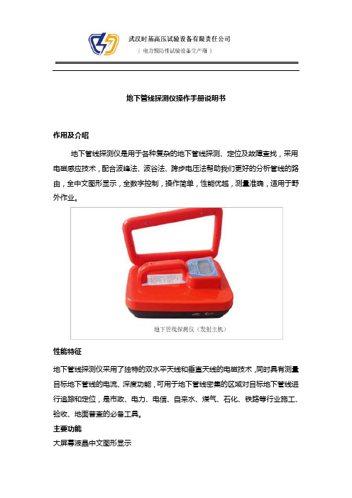
地下管线探测仪操作手册说明书作用及介绍地下管线探测仪是用于各种复杂的地下管线探测、定位及故障查找,采用电磁感应技术,配合波峰法、波谷法、跨步电压法帮助我们更好的分析管线的路由,全中文图形显示,全数字控制,操作简单,性能优越,测量准确,适用于野外作业。
性能特征地下管线探测仪采用了独特的双水平天线和垂直天线的电磁技术,同时具有测量目标地下管线的电流、深度功能,可用于地下管线密集的区域对目标地下管线进行追踪和定位,是市政、电力、电信、自来水、煤气、石化、铁路等行业施工、验收、地面普查的必备工具。
主要功能大屏幕液晶中文图形显示直埋电缆故障的精确定位自带充电电池,不需市电,便于野外操作多种探测模式,适合各种复杂管线的探测连续自动阻抗匹配,不需人工干预多天线、多通道,直接显示电缆埋深寻测50Hz运行电缆路径具有背光功能适合夜间使用电流测量用于平行管线内置欧姆表可测环路电阻地下未知管线的普查带电电缆的路径查找第四章:技术指标地下管线定位仪发射机技术指标:工作频率:音频、射频、组合频率匹配负载:5欧姆-3000欧姆功率输出:低挡(1W)、高挡(3W)工作模式:直连法、感应法、耦合法电池类型:8节一号电池连续工作时间:大于8小时阻抗显示:四位数字过热过流:自动保护工作温度:-10°C - 50°C尺寸大小:16cm×16cm×39 cm3重量:4公斤地下管线寻测仪接收机技术指标:工作频率:音频、射频、50无源交流频率天线模式:波谷法、波峰法信号强度表示:条形图、数字量程0--999声音指示:随信号强度变化的音调增益控制:按键式数字显示动态范围:105db电流指示:显示被测电缆的有效电流值最大探深:不小于5米直读深度测量:三位数字显示,最大直读深度2.5米精度*:音频:±(1-5)% 射频:±(5-12)%*与现场环境、非同心线的形状、邻近管线的分布等情况有关工作温度:-10°C - 50°C电池型号:6节二号电池连续工作时间:大于20小时。
测深仪说明书

华测测深仪产品系列D330测深仪操作手册第一版上海华测导航技术有限公司二○一○年九月目录第一章测深仪的工作原理 (1)§1.1测深仪简介 (1)§1.2测深仪的技术原理 (1)§1.2.1回声测深的原理 (2)§1.2.2测深仪相关参数 (2)§1.3测深仪的相关名词 (4)§1.3.1水深数据分类 (4)§1.3.2数据格式 (4)§1.3.3测量周期设置 (5)§1.3.4声速设置 (6)§1.3.5吃水深度设置 (7)第二章D330测深仪 (8)§2.1性能指标及特点 (8)§2.2标准配置单 (10)§2.3安装连接图 (11)§2.4测深软件主界面 (12)§ 2.4.1主菜单 (12)§ 2.4.2快捷工具栏 (13)§ 2.4.3状态栏 (14)§ 2.4.4测量参数设置 (14)§ 2.4.5调用屏幕键盘 (15)§2.5操作步骤 (16)§ 2.5.1水深数据采集 (16)§ 2.5.2水深数据回放 (16)§ 2.5.3水深数据复制和备份 (17)第三章与GPS联机测量 (18)§3.1连接GPS (18)§ 3.1.1与GPS设备的连接安装 (18)§ 3.1.2连接安装的注意事项 (18)§3.2水上测量软件的设置 (19)§3.3升级和注册 (22)§ 3.3.1固件升级 (22)§ 3.3.2注册测深仪 (22)第四章其他相关操作 (28)§4.1触摸屏的校准 (28)§4.2整机的维护注意事项 (30)§ 4.2.1主机的维护 (30)§ 4.2.2换能器的维护 (30)§ 4.2.3换能器连接杆的维护 (31)§ 4.2.4安全注意事项 (33)附录联系方式 (34)第一章测深仪的工作原理第一章测深仪的工作原理§1.1测深仪简介首先感谢您选择了华测D330型测深仪,这里我们将向您介绍该仪器的性能、操作和使用要点,它对于您掌握和使用这台仪器会有一定的帮助,并通过您的熟练应用为您带来外业工作上的方便、快捷和理想的测量成果。
福禄克网络测线仪使用说明书

FLUKE网络测试仪器说明书班级:330910姓名:***学号:********一、福禄克测试仪初始化步骤:1、充电:将Fluke dtx系列产品主机、辅机分别用电源适配器充电,直至电池显示灯转为绿色;2、设置语言:操作:将fluke dtx系列产品主机旋钮转至“SET UP”档位,按右下角绿色按钮开机;使用↓箭头;选中第三条“Instrument setting ”(本机设置)按“ENTER”进入参数设置,首先使用→箭头,按一下;进入第二个页面,↓箭头选择最后一项Language按“ENTER”进入; ↓箭头选择最后一项Chinese 按“ENTER”选择。
将语言选择成中文后才进行以下操作。
3、自校准:取fluke dtx系列产品Cat 6A/Class EA 永久链路适配器,装在主机上,辅机装上Cat 6A/Class EA 通道适配器。
然后将永久链路适配器末端插在Cat 6A/Class EA 通道适配器上;打开辅机电源,辅机自检后,“PASS”灯亮后熄灭,显示辅机正常。
“SPECIAL FUNCTIONS”档位,打开主机电源,显示主机、辅机软件、硬件和测试标准的版本(辅机信息只有当辅机开机并和主机连接时才显示),自测后显示操作界面,选择第一项“设置基准”后(如选错用“EXIT”退出重复),按“ENTER”键和“TEST”键开始自校准,显示“设置基准已完成”说明自校准成功完成。
二、设置福禄克测试仪基本参数操作:将fluke dtx系列产品主机旋钮转至“SET UP”档位,使用“↑↓”来选择第三条“仪器值设置”,按“ENTER”进入参数设置,可以按“←→”翻页,用“↑↓”选择你所需设置的参数,按ENTER进入参数修改,用“↑↓”选择你所需采用的参数设置,选好后按ENTER选定并完成参数设置。
三、福禄克测试仪测试过程:⒈根据需求确定测试极限值和电缆类型:通道测试还是永久链路测试?是CAT5E还是CAT6还是其他?⒉关机后将测试标准对应的适配器安装在主机、辅机上,如选择“TIA CAT5E CHANNEL”通道测试标准时,主辅机安装“DTX-CHA002”通道适配器,如选择“TIA CAT6A PERM.LINK”永久链路测试标准时,主辅机各安装一个“DTX-PLA002”永久链路适配器。
航海仪器 操作说明
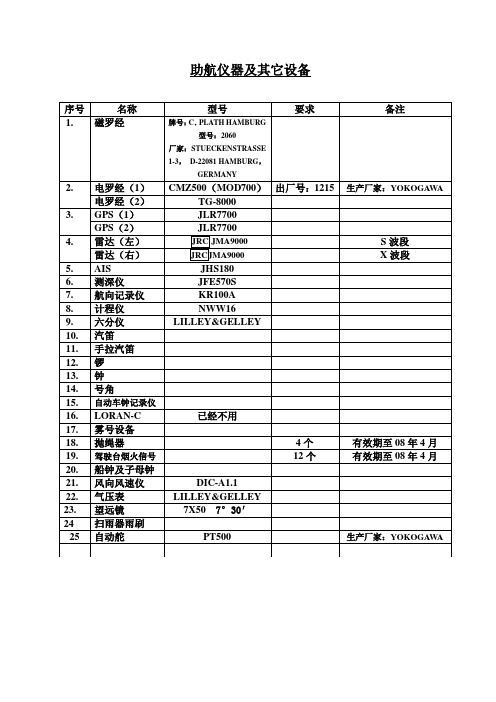
助航仪器及其它设备TG-8000电罗经操作说明一、开机1.打开罗经控制箱内的主电源开关,打开罗经操作面板上的电源开关(POWER),此时电罗经开始工作。
2.设置罗经启动时间。
3.设置罗经启动方位。
4.设置电罗经内部纬度系统。
5.调整罗经复示器与主罗经同步。
6.罗经稳定时间大约需6小时,此时禁止校正电罗经误差。
7.设置电罗经内部船速系统。
8.确认罗经系统的真方位。
9.选择罗经真方位显示模式。
二、关机1.关掉各电罗经复示器。
2.关掉主罗经操作面板上的电源开关。
3.关掉主罗经控制箱内的主电源开关,此时电罗经停止工作。
RT2048VHF操作说明一、开机1.旋转VHF操作面板上的电源及音量开关,打开电源并选择合适音量。
2.按数字键输入VHF频道。
3.调节操作面板上的SQ旋钮,进行静燥调节。
4.5.按/取消双功值守功能。
6.按二、关机旋转VHF操作面板上的电源开关,关掉电源,VHF停止工作。
KR100A航向记录仪操作说明一、开机1.向下掀开记录仪下方的盖板,将“RECORD”开关扳至“START”位置,“LIGHT”开关扳至“ON”位置,“SPEED”开关选择“NORMAL”2.向左掀开记录仪上方的盖板,按下操作面板右下角的电源开关(白色),此时记录仪开始工作并自动跟踪。
二、关机1.将上述“RECORD”开关扳至“STOP”位置,“LIGHT”开关扳至“OFF”位置。
2.按操作面板右下角的电源开关关掉电源,记录仪停止工作。
ECHO SOUNDER JFE-380 操作手册

General InformationThank you for purchasing the JFE-380 Echo-Sounder manufactured by Japan Radio Co., Ltd.. The JFE-380 conforms to the IMO (International Maritime Organization) performance standards, enabling seabed displays and digital depth displays.Before attempting to operate this equipment, please read this instruction manual thoroughly to ensure correct and safe operation in accordance with the warning instructions and operation procedures.You are strongly recommended to store this instruction manual carefully for future reference. In the event that you have an operational problem or malfunction, this manual will provide useful instructions.General Information iBefore You BeginSymbols Used In This ManualTo ensure that the equipment is used safely and correctly, and that the operator and third parties are not exposed to danger or damage, pictograms are used in this manual and on the equipment itself. These pictograms are described below.Please familiarize yourself with these pictograms and the meanings they convey before reading the rest of the manual.Failure to observe a warning indication, leading to incorrect handling, may result in death or serious injury to the operator.Failure to observe a caution indication, leading to incorrect handling, may result in injury to the operator, or physical damage to the equipment.Example PictogramsThis mark is intended to alert the user to the presence of precautions includingdanger and warning items. The picture in each mark alerts you to operations thatshould be carefully performed.This mark is intended to alert the user to the presence of prohibited activity. Thepicture/word in/beside each mark alerts you to operations that are prohibited.This mark is intended to alert the user to the presence of necessary instructions.The picture in each mark alerts you to operations that must be performed.Warning LabelsWarning labels are affixed to the cover of Display unit andConnection box.High voltage circuit exists inside the cover. Do not removethe cover.Do not attempt to remove, damage, or modify, the warninglabels.Before You Begin iiUsage HintsDo not remove the cover of this set. Otherwise, you may touch a high-voltage part and suffer from an electrical shock.Do not dismantle or modify this equipment. Failure to observe this warning may result in fire, electric shock, or damage.Do not place any vessels containing water or other liquids, or metal objects, on top of this equipment. If water is spilled on or metal objects fall into the equipment there is a risk of fire, electric shock, or damage.Do not insert or remove the power cord or operate switches with a wet hand.Otherwise, you may suffer from an electrical shock.Usage Hints iiiDo not damage, break or modify the power cord.When a heavy object is placed on the cord or the cord is heated, pulled, or forcibly bent, the cord will be broken resulting in a fire or an electrical shock.Do not use this set at a voltage other than the supply voltage stated on the set.Otherwise, a fire, an electrical shock, or a failure may occur.In the event of water of metal objects falling inside the equipment, immediately turn off the power switch, then contact JRC or its agent.There is a risk of file or electric shock if you continue to use the equipment.If you notice smoke, unusual smells, or abnormal heat coming from the equipment, immediately turn off the power switch, then contact JRC or its agent.There is a risk of fire, electric shock, or damage if you continue to use the equipment.There are no customer-serviceable parts inside. Unauthorized inspections and repairs could cause fires and electrical shock hazards.Please call our field representative or your nearest JRC office for inspection and repair services.Use only the specified fuses.The use of other fuse may cause fire and/or damage.The Main switch on the CQD-2082 I/F unit must be turned off during replacing a fuse.Usage Hints ivPlease contact JRC or its agent for the electricalinstallation of this equipment. Electrical installationsGNDUsage Hints vWhen removing the power cord, be sure to remove the power cord terminal correctly.If the power cord is pulled, the cord may be damaged resulting in a fire or an electrical shock.Do not install the units on the place being poor ventilation.Otherwise, the set that is heated may cause a fire or failure.For safety when the equipment is to be left unused for an extended period, turn off the power switch.When turning on the power, be sure not to press any operator panel key at the same time. Alternates to the hardware configuration of the until could cause the unit to malfunction.Take care when laying the transducer cable, power cable, and earth lead as positioning has an affect on electromagnetic interference. There is a risk of interfering with other equipment or the echo-sounder being interfered with by the other equipment.After installing the echo-sounder, turn on the power to all other equipment to check for interference with or from all the equipment. Interference may cause malfunctions.Usage Hints viExternal ViewExternal View viiContentsGeneral Information ..................................................................................................... Before You Begin ......................................................................................................... Usage Hints ................................................................................................................... External View ................................................................................................................ Explanation of Terms ...................................................................................................1. Introduction ..............................................................................................................1.1 Function ...........................................................................................................…1.2 Feature ............................................................................................................….1.3 Components ........................................................................................................1.4 Construction ........................................................................................................1.5 System Configuration ..........................................................................................2. Control Panel .........................................................................………………………..3. Display ................................................................................................................…..3.1 Standard mode ....................................................................................................3.2 History mode ..................................................................................................…..3.3 Docking mode ..................................................................................................…4. Operation ..................................................................................................................4.1 Basic Operations ..................................................................................................4.2 Menu Operations .................................................................................................4.3 Master Reset ........................................................................................................5. Replacing the Fuses .......................................................................................……..6. Consider Installation ...............................................................................................7. Installation ...............................................................................................................7.1 Installing the Recorder Unit ...........................................................................…..7.2 Installing the Transducer ......................................................................................7.3 Connecting Components .....................................................................................8. Troubleshooting ......................................................................................................9. After-sales Service ..................................................................................................9.1 When Requesting Servicing .................................................................................9.2 Recommendations for Inspection and Maintenance.............................................10. Disposal ..............................................................................................................…10.1 Disposal of this equipment .............................................................................…11. Specifications ....................................................................................................…. Appendix ....................................................................................................…………… i iii iv viii x 1 1 1 2 3 5 6 7 7 8 9 10 10 16 27 28303132 34373839 393940 404142Information ...................................... Please refer to ‘Place of Contact’ on back cover.Explanation of TermsBeam angle: The angle that sound waves spread out from the transducer. Sound waves spread out in a conical manner taking the center of the bottom surface of the transducer at the apex of the cone.Bubbling: The phenomenon where the image of the seabed is interrupted due to air bubbles caused by the ship's hull or the propeller during a voyage.IMO: abbreviation for the International Maritime Organization.MED: abbreviation for the Marine Equipment Directive. This is the directive for marine equipment in Europe. This directive unifies format approval standards implemented separately by each European.NMEA0183: formats for the National Marine Electronics Association. NMEA0183 is the format used when sending or receiving depth, position, water temperature, ship speed and other information between marine equipment.STC: Sensitivity Time Control is used for reduce shallow water clutter. Shallow seabed echo is strong and deep seabed echo is weak. So, the STC controls the sensitivity to normalize seabed echo for precision seabed tracking.Transducer: Device that emits ultrasonic waves in water and receives the signals reflected off the seabed. This is equivalent to an antenna on a radio.UTC: abbreviation for the Universal Time Coordinated.Explanation of Terms ix1. Introduction1.1 FunctionThe JFE-380 Echo-Sounder consists of a transducer mounted on the bottom of the ship's hull and a main unit that displays information on the depth and formation of the seabed.This information is gained by using ultrasonic waves sent from the transducer that are then reflected off the sea bottom and picked up again by the transducer. The JFE-380 also has the following functions:(1) depth alarm, (2) power fail alarm, (3) output of depth data, (4) output of depth and power fail alarms.1.2 FeatureThe JFE-380 features the following:• Tree display modes; standard, history, and docking.• Depth data for last 24 hours in memory to play back the past sounding information.• Dual frequency mode and two transducers are available in option. (*requires an optional equipment)• When the depth becomes shallower than a previously set value, a depth alarm is issued by buzzer and LCD display.• When power is cut to the main unit, a power fail alarm is issued by buzzer and LCD display. • Contact signals can be output for both depth and power fail alarms.• Data on depths can be output.• No need for time-consuming reading of depths using a scale against the profile of the seabed on the paper! The current depth can be seen at a glance.• Self-diagnostic functions can be selected from a menu, improving ease of maintenance. 1. Introduction 11.3 ComponentsThis section lists the components.Name Type No. Qty.RemarksDisplay unit NJA-98 1Connection box NQD-2120 1TX/RX cable CFQ-9129 1 10mPower supply cable CFQ-9130 1 10mCommunication cable CFQ-9133 1 10mMatching box (primary) AW-154F 1 200kHztransducer mounting (primary) NKF-341 1 200kHz (with cable 20,30,40m)AW-154F 1 200kHzMatching box (secondary) AW-154F-50 1 50kHzNKF-341 1 200kHz (with cable 20,30,40m) NKF-345 1 50kHz (with cable 20,30,40m) Transducer mounting (secondary) NKF-392C 1 200kHz (with cable 20,30,40m)Printer NKG-91 1External Buzzer CGC-300B 1Flush mounting kit BRBX05339 1 Color : MUNSELL N4Option Table mounting kit BRBX05353 11. Introduction 21.4 ConstructionThe following shows the external dimensions of the JFE-380.1. External Dimension of JFE-380Unit : mm2. Dimensions of AW-154F/AW-154F-50 Matching boxUnit : mm1. Introduction 3The external dimensions illustrated below are for the standard equipment. Please refer to the separately supplied drawings if your specifications are not standard.1. NKF-341/NKF-345 (Installed on ship’s bottom)Unit : mm2. NKF-392C (Installed on ship’s bottom)Unit : mm1. Introduction 41.5 System ConfigurationC o n n e c t i o n b o x1. Introduction 52. Control PanelThis section describes the names and functions of the control panel and its controls. 2 1346 58 7911 10Figure 2-1 Control PanelNo. Name Function 1ACK Cancels the buzzer. 2 MENU Displays the menu.3 Arrows Move a cursor.4ENT Selects an item. 5 MODE Switches the display modes.6 CLR Clears an item.7 (RANGE) +/– Switches the depth range to shallow or deep. 8 (GAIN) +/– Adjusts the sensitivity high or low.9 DAY NIGHT Enhances the visibility of the screen.10PWR/PANEL Switches the equipment power on and off, adjusts thebrightness of the panel. Press and hold both the PWR/PANEL and the BRILL keys to turn off the power.11 BRILL Adjusts the screen brilliance.2. Control Panel 63. Display3.1 Standard mode (dual frequency)3 Display 73.2 History modeKeel height value3. Display 83.3 Docking mode3. Display 94. Operation4.1 Basic OperationsTurning Power OnPress and hold the PWR/PANEL key for three seconds.Turning power OFFPress and hold both the PWR/PANEL and the BRILL keys for three seconds.PANELPress the PWR/PANEL key, and use the arrow keys to adjust the control panel brightness. The control panel illumination can not be turned fully off, it can only be dimmed.BRILLThe screen brilliance is adjusted by pressing the BRILL key. Set the brilliance to optimum visibility by using the arrow keys.Note:Use the Day/Night Vision also to enhance the visibility of the screen depending in the surrounding light condition.4. Operation 10Each time you press the (RANGE) + key, the measuring range increases in the sequence 10, 20, 50, 100, 200, 500, 800 meters.Each time you press the (RANGE) – key, the measuring range decreases in the sequence 800, 500, 200, 100, 50, 20, 10 meters.Note:1. As per the draft setting, the seabed image may shift outside the depth measuring range.2. You must display the seabed, otherwise you don’t see the depth value.In the Automatic range mode, the range scale is automatically adjusted.Turn on the power or press and hold both the (RANGE) + and – keys for three seconds. Once Automatic range mode is selected, the text “AUTO” will appear on the screen.The Automatic range mode is cancelled by pressing the (RANGE) + or – key.Note:1. The Automatic range mode can be set by a dedicated menu function.2. Default setting of the automatic range is 10m.4. Operation 11Select the step from 0 to 30.Pressing the (GAIN) + key increases sensitivity.Pressing the (GAIN) – key decreases sensitivity.If the receiver sensitivity is set too high, noise will also be displayed on the screen, making it difficult to distinguish the seabed. The seabed color should be orange, red or color between orange and red. Adjust the sensitivity to an appropriate value by monitoring the image being plotted on the screen. (See figure below)IncreasesensitivityGood Decrease sensitivityAutomatic Gain In the Automatic gain mode, the sensitivity is automatically adjusted.Press and hold both the (GAIN) + and – keys for three seconds. Once Automatic gain mode is selected, the text “GAIN:AUTO” will appear on the screen and LONG will be selected at STC function.The Automatic range mode is cancelled by pressing the (GAIN) + or – key.Note:1. The Automatic gain mode can be set by a dedicated menu function.2. Default setting of the automatic gain is 10 in the steps 0 to 20.4. Operation 12Pressing the MODE key choose the display mode among STANDARD, HISTORY, and DOCKING.[Single frequency]Each press of the MODE key brings up the display mode as follows, “Standard mode, History mode, Docking mode.”[Dual frequency]Each press of the MODE key brings up the display mode as follows, “Single frequency standard mode (primary), Single frequency standard mode (secondary), Dual frequency standard mode, Single frequency history mode (primary), Single frequency history mode (secondary), Docking mode.”Use the Day/Night Vision to enhance the visibility of the screen depending in the surrounding light condition.Select day1, day2, night1, or night2.Note:The color be set by a dedicated menu function.Press the ACK key to cancel the depth alarm buzzer.4. Operation 134. Operation 144. Operation 154.2 Menu OperationsDISPLAYALARMINITIAL PRINTER CONT COMMUNICATION MAINTENANCE > > > > > >Press the MENU key. The window shown above appears on the screen. While watching the display, use the arrow keys to select the item to be changed. The selected item is highlighted on the display. In the figure at above, "DISPLAY" is selected.When an item is highlighted, press the ENT key to change the setting.To switch to normal operating, press the CLR key several times.Note:You can press the MENU key also to return to normal operation at any time the menu window is displayed.4. Operation 16DISPLAYSCROLL SPEED CLUTTER INTERFERENCE GAINRANGEDRAFT CURSOR FAST4OFF AUTO MANUAL 6.1ONScroll speed: Choose one among slow, standard, and fast.Clutter: Suppresses small noise. Choose one among 11 levels. “0” is the weakest. Interference: Eliminates noise from other boats. “OFF” does not eliminate the noise.“IR1” compares it with the last data. “IR2” compares it with the last two data. “IR3” compares it with the last three data.Gain: Choose manual or automatic.Range: Choose manual or automatic.Draft: Enter the desired value. The draft can be set between 0.0 and 50.0 m in steps of 0.1 m.Cursor: “OFF” does not display the cursor. “ON” displays the cursor. “AUTO” displays the cursor for 30 seconds after the cursor movement is stopped.ALARMKEY ACK RELAY MODE DEPTH ALARM SYSTEM ALARM ON CONTINUOUS >>Key acknowledgement: Enables / disables the keypads beep. Relay mode: Choose intermittent or continuous.4. Operation 17DEPTH SETTING20.0Display the window shown above.Pressing and holding the upward-arrow key increases the depth setting of the depth alarm. Pressing and holding the downward-arrow key decreases the depth setting of the depth alarm.Press the ENT key to finish setting.If the measured depth is less than the set depth alarm value, a warning character blinks and the buzzer sounds.Notes:1. The buzzer sounds for depth and system alarms. You can check which alarm is beingissued from the blinking characters.2. If, due to bubbling, etc., it is not possible to discriminate the sea bottom, it is also notpossible to trigger the depth alarm. When sailing in shallow waters, please check the sea bottom reflected on the screen.3. The alarm tone sounds from the hole at the front panel. Do not block this hole.The currently set depth alarm is displayed on the screen.Note:The depth can be set between 0.0 and 99.9 meters.Highlight the alarm item you wish to activate or deactivate.Select OFF to deactivate the alarm.Select ON to activate the alarm.Press the ENT key to finish setting.4. Operation 18INITIALMEMORY INTERVAL COLORDEPTH DISPLAY MODE PRIMARY SECONDARYDATE/TIME 30S > TRAN >>>Memory interval: “30S” saves the sounding data every 12 hours. “1min” saves the sounding data every 24 hours.Color: Adjust color of the screen and character for the DAY NIGHT key.Depth display mode: “SURF” displays the depth below water surface. “TRAN” displays the depth below the transducer. “KEEL” displays the depth below the keel. (see figure A) Primary: Enter the data of the primary transducer; frequency, position, STC, inner, and keel. Secondary: Enter the data of the secondary transducer; frequency, position, STC, inner, and keel.Date/time: Set the time, the date, and a time difference. GPS synchronization “OFF” uses the inner clock. GPS synchronization “ON” uses the ZDA data to synchronize the inner clock.4. Operation 19PRINTER CONTPRINTERPRINT MODELOG LENGTHSPEED ON COPY 10min 4800bpsPrinter:Enables / disables to print.Print mode: “COPY” prints the data displayed on the present screen.“HISTORY” prints allthe saved data graphically.“LOG” prints a specific period of the saved data. (see figure C for example)Log length:Choose a log length for “LOG” which explained just above.Speed: Choose a baud rate of the printer port.Figure C4. Operation 20DEPTHVer1.5Ver2.3ALLDisplay the window shown above. The format changes each time you press the up or downward-arrow key.Notes:1. There are three output formats: NMEA0183V2.3, NMEA0183V1.5, or ALL.2. In the case of NMEA0183V2.3, only "SDDPT" sentences are output.$SDDPT, xxx.x, x.x, x.x *hh (CR)(LF)(1) (2) (3) (4)(1) Depth measured from the transducer regardless of the depth display mode setting (inmeters only.)(2) According to the depth display mode:DISP-SURF: Draft value (no + or – sign preceding values) DISP-TRANS: 0.0DISP-KEEL: Keel height compensation (– sign preceding values)(3) Measuring range: RANGE (in meters only)(4) Checksum (result after each ASCII code of every character between "S" just after "$" and"X" just before " * " is EXORed.)3. In the case of NMEA0183V1.5, the output sentence varies according to the depth displaymode setting.• When DISP-SURF is set, only the "SDDBS" sentence is output.$SDDBS, xxx.x, f, xxx.x, M, xxx.x, F(CR)(LF)(1) (2) (3)• When DISP-TRANS is set, only the "SDDBT" sentence is output.$SDDBT, xxx.x, f, xxx.x, M, xxx.x, F(CR)(LF)(1) (2) (3)• When DISP-KEEL is set, only the "SDDBK" sentence is output.$SDDBK, xxx.x, f, xxx.x, M, xxx.x, F(CR)(LF)(1) (2) (3)The field values are the same in each of the three sentence types:(1) Depth value after compensation (in feet)(2) Depth value after compensation (in meters)(3) Depth value after compensation (in fathoms)(4) No check sum4. Operation 21ALARMOFFONDisplay the window shown above. Use the arrow keys to select OFF or ON.When OFF is selected, ALR sentence is not output.When ON is selected, ALR sentence is output according to the depth and system alarm setting.Notes:ALR(Set Alarm State)$SDALR,hhmmss.ss,xxx,A,A,c--c*hh<CR><LF>(3)(4)(5)(1) (2)1. Time of alarm condition change,UTC2. ID number of the alarm source351 primary depth alarm352 secondary depth alarm353 primary depth lost354 secondary depth lost356 recording paper is not good357 printer connection is not good360 primary output data is not good361 primary input data is not good362 primary input sensitivity data is not good363 secondary output data is not good364 secondary input data is not good365 secondary input sensitivity data is not good366 backup data area is not good3. Alarm condition (A = threshold exceeded, V = not exceeded)4. Alarm's acknowledge state (A = acknowledged, V = unacknowledged)5. Alarm's description text4. Operation 22SYSTEMOFFONDisplay the window shown above. Use the arrow keys to select OFF or ON.When OFF is selected, a cyclical PJRC is not output.When ON is selected, PJRC, PJRCL, and PJRCM is output to the depth output port. PRINTER PORT OUTPRINTERPCDisplay the window shown above. The mode switches each time you press the up or downward-arrow key.When PRINTER is selected, a printer control signal is output.When PC is selected, PJRCP is output according to the print mode setting. PJRCM is output after PJRCP.Notes:1. Any settings output PJRCU every 1 second.2. Output sentence and sourcePJRCU depth, offset, selected rangePJRCL maintenancePJRCM system datadataPJRCP print4. Operation 23SELF TEST CONTROL UNIT LCD UNITKEY UNIT PRINTER TEST ALARM TEST > > > > > >Display the window shown above. Use the up or downward-arrow key to select CONTROL UNIT.Press the ENT key to start the memory test.The results of the memory test are shown on the screen.• During testing, nothing is shown on the screen.• The results are shown for each PROM, SRAM, and VRAM.If OK : OKIf no good : NGIf NG is displayed, the Transducer Controller is faulty and requires servicing. (See the list of offices at the end of this manual.)SELF TEST CONTROL UNIT LCD UNITKEY UNIT PRINTER TEST ALARM TEST > > > > > >Display the window shown above. Use the up or downward-arrow key to select color.Press the CLR key to exit.This test fills the whole screen with colors, which are black, red, green, blue, and white. The color changes each time you press the up or downward-arrow key. If there is any dropout, the Panel or Transducer Controller may be faulty. Please contact JRC or its agent. (See the list of offices at the end of this manual.)4. Operation 24KEY UNITBRILLDisplay the window shown above.Press each location on the panel.• If operation is OK, a key name is displayed in the key unit window. In the figure at above, the result of that the BRILL key is pressed.• If operation is NG, nothing remains.If faulty, the Panel or Transducer Controller may be faulty and may require servicing. (See the list of offices at the end of this manual.)SELF TESTCONTROL UNITLCD UNITKEY UNITPRINTER TESTALARM TEST > > > > >>Display the window shown above.Use the up or downward-arrow key to select PRINTER TEST.Press the ENT key to start the recording paper surface check.This check prints a test pattern on the recording paper. (See figure B for example) If the printing is blurred, it may be faulty and may require servicing. Please contact JRC or its agent. (See the list of offices at the end of this manual.)Figure B4. Operation 25。
船舶地面站操作手册驾驶室仪器操作规程

INMARSAT-C船舶地面站操作规程
INMARSAT船舶地面站操作规程
中/高频/SSB无线电装置操作规程
甚高频无线电装置操作规程
高频无线电装置操作规程
NVATEX航行警告接收机操作规程
气象传真机操作规程
AIS船用全球自动识别系统操作规程
回声测深仪操作规程
GPS接收机操作规程
自动操舵仪操作规程
电罗经操作规程
磁罗经操作规程
电磁记程仪操作规程
VDR船载航行数据记录仪操作规程
操作规程
注意事项备注
双向无线电话操作规程
SART 操作规程
EPIRB 操作规程
INMARSAT-F 操作规程
RADAR 雷达操作规程
RADAR雷达操作规程
雷达操作规程
舵机操作程序
1、通知机舱舵机供电。
2、打开舵机开关,选择舵机组。
3、选择操纵方式,随动方式。
4、转动舵轮试验舵角指示。
5、最后舵角指示回零。
6、舵机备好。
应急舵操作规程。
测深仪使用说明
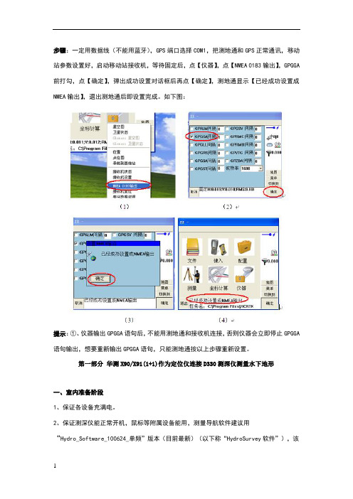
步骤:一定用数据线(不能用蓝牙),GPS端口选择COM1,把测地通和GPS正常通讯,移动站参数设置好,启动移动站接收机,等待固定后,点【仪器】,点【NMEA 0183输出】,GPGGA 前打勾,点【确定】,弹出成功设置对话框后再点【确定】,测地通显示【已经成功设置成NMEA输出】,退出测地通后即设置完成。
如下图:提示:①、仪器输出GPGGA语句后,不能用测地通和接收机连接,否则仪器会立即停止GPGGA 语句输出,想要重新输出GPGGA语句,只能测地通按以上步骤重新设置。
第一部分华测X90/X91(1+1)作为定位仪连接D330测深仪测量水下地形一、室内准备阶段1、保证各设备充满电。
2、保证测深仪能正常开机,鼠标等附属设备能用,测量导航软件建议用“Hydro_Software_100624_单频”版本(目前最新)(以下称“HydroSurvey软件”),该注册的地方提前注册好(HydroSounder软件和HydroSurvey软件),数据通讯测试好,如:GPS数据可输入HydroSurvey软件、HydroSounder软件可测水深(若测试,要插换能器且换能器一定要放水里,以防打坏换能器或损坏工控机)、水深数据可输入HydroSurvey软件。
3、保证GPS搜星、固定正常,输出GPGGA格式正常,注册正常。
4、控制点或参数找好,若需要做背景图提前做好。
二、外业准备阶段1、正常架设RTK(1+1),正常固定后去做点校正(同陆地操作一样)。
注:如果在同一个工地多次架站,注意HydroSurvey软件没有“重设当地坐标”功能,所以第二次、第三次。
架站,一定架设在已知点或每次都重新做点校正。
2、上船安装好换能器,保证换能器吃水深浅合适,固定换能器连接杆子时保证杆子垂直于水平面,保证杆子上下固定、前后固定、左右固定,连接好测深仪各设备后,测深仪开机。
注:换能器建议安装在中间靠船头方向一点的地方(船头上下跳动较大,船尾发动机、螺旋桨容易产生杂波),吃水可米不等,一般湖泊、河流吃水小一点,海洋测量吃水深一点,一般米(吃水太浅容易产生气泡,吃水太深,岸边测量容易换能器搁浅)。