最新Cisco路由模拟器实验总汇
2024版年度思科路由器配置笔记与交换机模拟器教程

2023REPORTING 思科路由器配置笔记与交换机模拟器教程•路由器与交换机基础•思科路由器配置详解•思科交换机配置详解•思科模拟器使用方法•故障排查与网络优化•总结与展望目录20232023REPORTINGPART01路由器与交换机基础路由器与交换机简介路由器一种网络设备,用于连接不同网络,实现网络间的数据传输和路由选择。
交换机一种网络设备,用于在同一网络内部进行数据传输,实现设备间的快速通信。
网络拓扑结构与设备连接网络拓扑结构描述网络中设备连接方式的模型,常见的有星型、树型、环型和网状型等。
设备连接通过网络线缆将路由器、交换机、计算机等设备连接起来,形成一个可通信的网络。
IP地址与子网掩码IP地址用于唯一标识网络中的设备,由32位二进制数组成,分为网络地址和主机地址两部分。
子网掩码用于划分IP地址中的网络地址和主机地址,通过与IP地址进行按位与运算得到网络地址。
A BC D路由器与交换机的基本配置路由器基本配置包括设置路由器的主机名、密码、接口IP 地址、路由协议等。
配置文件备份与恢复对路由器和交换机的配置文件进行备份,以便在设备出现问题时可以快速恢复配置。
交换机基本配置包括设置交换机的主机名、密码、VLAN 、端口速率、双工模式等。
远程管理与故障排除通过远程登录到路由器和交换机进行管理和故障排除,提高网络维护效率。
2023REPORTINGPART02思科路由器配置详解进入接口配置模式使用`interface`命令进入特定接口的配置模式,如`interface FastEthernet 0/0`。
启用接口使用`no shutdown`命令启用接口,使其能够正常工作。
配置IP地址在接口配置模式下,使用`ip address`命令为接口配置IP地址和子网掩码,如`ip address 192.168.1.1 255.255.255.0`。
配置接口带宽和延迟可以使用`bandwidth`和`delay`命令来配置接口的带宽和延迟参数,以优化网络性能。
实验报告路由器配置

实验二:路由器互连实验一、实验目的:1. 路由器1.、路由器2、路由器3互连。
2. 配置虚拟终端(telnet)。
二、实验要求:1.熟悉Cisco路由器模拟软件Cisco packet tracer的使用;2.利用该软件设计一个包含3个路由器、交换机的网络,网络拓扑、网络数量、路由器型号自定;3.根据所设计网络的结构,掌握网络规划方法。
三、实验步骤:1.首先在模拟器中构建出网络拓扑结构如下:2.在控制台微机的超级终端中分别配置路由器R1,R2,R3以下命令均以Router1为例配置主机名,配置模式口令格式如下:Router>enableRouter#config tRouter(config)#hostname Router1Router1(config)#enable secret 501Router1(config)#^Z配置接口(局域网和广域网)IP地址配置命令格式如下:Router1#config tRouter1(config)#int FastEthernet0/0Router1(config-if)#ip address 192.5.5.1 255.255.255.0Router1(config-if)#no shutdownRouter1(config-if)#^Z配置Router Rip协议命令格式如下:Router1#config tRouter1(config)#router ripRouter1(config-router)#network 192.5.5.0Router1(config-router)#network 201.100.11.0Router1(config-router)#^Z广域网接口协议配置命令格式如下:Router1#config tRouter1(config)#int Serial0/0/1Router1(config-if)#encapsulation hdlcRouter1(config-if)#bandwidth 64Router1(config-if)#^Z广域网接口时钟配置命令格式如下:Router1#config tRouter1(config)#int Serial0/0/1Router1(config-if)#clock rate 64000Router1(config-if)#^Z保存新的启动配置文件copy 命令格式如下:Router1#copy running-config startup-config路由器状态查看命令show常用格式如下:show interface[type slot/port]:该命令可以查看相关接口信息。
CISCO路由器PPPoE实验报告
CISCO路由器PPPoE实验报告题⽬:PPPOE实验实验拓扑如下:实验要求:1.在pppoe-client2路由器上使⽤NAT协议,让内部主机能够上⽹2.路由器pppoe-client2和pppoe-client1通过pppoe协议拨号连接pppoe-server服务器,3.在pppoe-server和ISP-router之间使⽤ospf路由选择协议实验⽬的:掌握1.pppoe在路由器上的配置过程2.NAT3.单区域ospf实验步骤:1.使⽤⼩凡模拟器搭建实验环境。
2.2.在pppoe-server 路由器上配置如下PPPoe-server(config-if)#username cisco password cisco 创建⼀个拨号帐号。
PPPoe-server(config)#vpdn enable //启⽤vpdn虚拟私有拨号⽹络协议PPPoe-server(config)#vpdn-group adsl0 //创建⼀个虚拟私有拨号⽹络组,起名为adsl0 PPPoe-server(config-vpdn)#accept-dialin //允许拨⼊改组PPPoe-server(config-vpdn-acc-in)#protocol pppoe //并启⽤pppoe协议%Only one PPPoE VPDN group can be configuredPPPoe-server(config-vpdn-acc-in)#virtual-template 1 //关联⼀个虚拟接⼝PPPoe-server(config-vpdn-acc-in)#exitPPPoe-server(config-vpdn)#pppoe limit per-mac 10 //限制拨号连接的mac数⽬为10PPPoe-server(config)#int f0/0 启⽤物理接⼝PPPoe-server(config-if)#ip add 1.1.1.1 255.255.255.0 配置ip地址PPPoe-server(config-if)#no shutPPPoe-server(config-if)#pppoe enable 并在该物理接⼝下启⽤pppoe协议PPPoe-server(config-if)#int virtual-template1 配置虚拟接⼝PPPoe-server(config-if)#ip address 200.0.0.1 255.255.255.0PPPoe-server(config-if)#peer default ip address pool ad 指定拨⼊端的iP池,名字为ad PPPoe-server(config-if)#pppauthentication chap pap callin 启⽤混合认证⽅式PPPoe-server(config-if)#ppp ipcp dns 202.102.128.68 202.102.134.68 给拨⼊端指派dns PPPoe-server(config-if)#ip local pool vt1 200.0.0.20 200.0.0.254 指定拨⼊端能够使⽤的ip范围PPPoe-server(config)#PPPoe-server(config)#router ospf 10 启⽤ospf路由选择协议PPPoe-server(config-router)#net 200.0.0.0 0.0.0.255 area 0 通告直连⽹络号PPPoe-server(config-router)#net 100.0.0.0 0.0.0.255 area 0PPPoe-server(config-router)#pppoe-server(config)#do sho ip rou ospf 查看ospf路由表5.0.0.0/32 is subnetted, 1 subnetsO 5.5.5.5 [110/11] via 100.0.0.2, 00:03:07, FastEthernet1/0pppoe-server(config)#pppoe-server(config)#do ping 5.5.5.5 测试Type escape sequence to abort.Sending 5, 100-byte ICMP Echos to 5.5.5.5, timeout is 2 seconds:Success rate is 100 percent (5/5), round-trip min/avg/max = 20/211/364 mspppoe-server(config)#do sho ip rou ospf5.0.0.0/32 is subnetted, 1 subnetsO 5.5.5.5 [110/11] via 100.0.0.2, 00:03:07, FastEthernet1/0pppoe-server(config)#在pppoe-client2上配置如下pppoe-client2(config)#vpdn enable 同上,在路由器作为拨⼊端时也要启⽤vpdn协议pppoe-client2(config)#int f0/0 pppoe-client2(config-if)#no shut 启⽤连接拨号的物理接⼝pppoe-client2(config-if)#*Mar 1 00:19:54.511: %LINK-3-UPDOWN: Interface FastEthernet0/0, changed state to up*Mar 1 00:19:55.511: %LINEPROTO-5-UPDOWN: Line protocol on Interface FastEthernet0/0, changed state to up pppoe-client2(config-if)#pppoe enable 同样启⽤pppoe协议pppoe-client2(config-if)#*Mar 1 00:20:56.283: %LINK-3-UPDOWN: Interface Virtual-Access1, changed state to up*Mar 1 00:20:57.283: %LINEPROTO-5-UPDOWN: Line protocol on Interface Virtual-Access1, changed state to up pppoe-client2(config-if)#pppoe-client dial-pool-number ?<1-255> Dialer pool numberpppoe-client2(config-if)#pppoe-client dial-pool-number 1 定义⼀个拨号池为1pppoe-client2(config-if)#exitpppoe-client2(config)#int dialer0 启⽤拨号接⼝pppoe-client2(config-if)#ip add negotiated ip地址协商pppoe-client2(config-if)#ip mtu 1492 默认mtu为1500由于pppoe包头占⽤8字节pppoe-client2(config-if)#no shutpppoe-client2(config-if)#encapsulation ppp 启⽤封装协议pppoe-client2(config-if)#ppp authentication chap pap callin 指定认证⽅式pppoe-client2(config-if)#ppp chap hostname ciscopppoe-client2(config-if)#ppp chap password ciscopppoe-client2(config-if)#ppp pap sent-username cisco password ciscopppoe-client2(config-if)#dialer pool 1 启⽤拨号池此时拨号⾃动开始连接pppoe-client2(config-if)#ppp ipcp dns request 请求获取dnspppoe-client2(config-if)#exitpppoe-client2(config)#int f0/0pppoe-client2(config-if)#ip add 2.2.2.2 255.255.255.0pppoe-client2(config-if)#no shutpppoe-client2(config-if)#exitpppoe-client2(config)#int f0/0pppoe-client2(config-if)#shutpppoe-client2(config-if)#*Mar 1 00:38:58.891: %LINK-5-CHANGED: Interface FastEthernet0/0, changed state to administratively down*Mar 1 00:38:59.891: %LINEPROTO-5-UPDOWN: Line protocol on Interface FastEthernet0/0, changed state to down pppoe-client2(config-if)#*Mar 1 00:39:55.127: %DIALER-6-UNBIND: Interface Vi2 unbound from profile Di0pppoe-client2(config-if)#*Mar 1 00:39:55.135: %LINK-3-UPDOWN: Interface Virtual-Access2, changed state to down pppoe-client2(config-if)# *Mar 1 00:39:56.115: %LINEPROTO-5-UPDOWN: Line protocol on Interface Virtual-Access2, changed state to down pppoe-client2(config-if)#pppoe-client2(config-if)#pppoe-client2(config-if)#no shutpppoe-client2(config-if)#*Mar 1 00:41:33.659: %LINK-3-UPDOWN: Interface FastEthernet0/0, changed state to up*Mar 1 00:41:34.659: %LINEPROTO-5-UPDOWN: Line protocol on Interface FastEthernet0/0, changed state to up pppoe-client2(config-if)#exi*Mar 1 00:41:50.519: %DIALER-6-BIND: Interface Vi2 bound to profile Di0pppoe-client2(config-if)#ex*Mar 1 00:41:50.527: %LINK-3-UPDOWN: Interface Virtual-Access2, changed state to up pppoe-client2(config-if)#pppoe-client2#^Zpppoe-client2#*Mar 1 00:41:54.491: %SYS-5-CONFIG_I: Configured from console by console*Mar 1 00:41:55.159: %LINEPROTO-5-UPDOWN: Line protocol on Interface Virtual-Access2, changed state to uppppoe-client2#sho ip int bri 获取到pppoe-server分配的ip地址,拨号成功Interface IP-Address OK? Method Status Protocol FastEthernet0/0 2.2.2.2 YES manual up up Ethernet1/0 unassigned YES unset administratively down down Ethernet1/1 unassigned YES unset administratively down down Ethernet1/2 unassigned YES unset administratively down down Ethernet1/3 unassigned YES unset administratively down down Virtual-Access1 unassigned YES unset up up Virtual-Access2 unassigned YES unset up up Dialer0 200.0.0.20 YES IPCP up up pppoe-client2#ping 200.0.0.1Type escape sequence to abort.Sending 5, 100-byte ICMP Echos to 200.0.0.1, timeout is 2 seconds:Success rate is 100 percent (5/5), round-trip min/avg/max = 8/175/392 mspppoe-client2#以下是为了内⽹主机能够通过pppoe-client来nat上⽹的配置。
cisco模拟器之------交换机、路由器、vlan的综合实例

cisco模拟器之------交换机、路由器、vlan的综合实例主要实现功能:a)位于路由器同⼀侧的不同⽹段的主机之间实现通信。
b) 位于不同路由器的主机之间实现通信。
⽹络拓扑图:命令配置:switch0的配置:Switch(config)#vlan 11 //划分⼦⽹11Switch(config-vlan)#name T11Switch(config-vlan)#no shutdownexitSwitch(config)#vlan 22 //划分⼦⽹22Switch(config-vlan)#name T22Switch(config-vlan)#no shutdownexitSwitch(config)#interface fastethernet 0/1Switch (congfig-if)#switchport mode trunk //把0/1接⼝设为trunk模式Switch (config-if)#no shutdownSwitch (config-if)#exitSwitch(config)#interface fastethernet 0/2 //把0/2接⼝划分给⼦⽹11Switch (congfig-if)#switchport access vlan 11Switch (config-if)#no shutdownSwitch (config-if)#exitSwitch(config)#interface fastethernet 0/3Switch (congfig-if)#switchport access vlan 22 //把0/3接⼝划分给⼦⽹22Switch (config-if)#no shutdownSwitch (config-if)#exitSwitch1的配置:Switch(config)# vlan 11Switch(config-vlan)#name T11Switch(config-vlan)#no shutdownexitSwitch(config)# vlan 22Switch(config-vlan)#name T22Switch(config-vlan)#no shutdownexitSwitch(config)#interface fastethernet 0/1Switch (congfig-if)#switchport mode trunkSwitch (config-if)#no shutdownSwitch (config-if)#exitSwitch(config)#interface fastethernet 0/2Switch (congfig-if)#switchport access vlan 11Switch (config-if)#no shutdownSwitch (config-if)#exitSwitch(config)#interface fastethernet 0/3Switch (congfig-if)#switchport access vlan 22Switch (config-if)#no shutdownSwitch (config-if)#exitRouter0的配置:Switch (config)#int f0/1.1 //在0/1接⼝下划分⼦接⼝0/1.1Switch (config)#int f0/1.2 //在0/1接⼝下划分⼦接⼝0/1.2Switch(config)#interface fastethernet 0/1.1 //配置⼦接⼝0/1.1的路由信息Switch (congfig-subif)#encapsulation dot1Q 11 //单臂路由Switch (config-subif)#ip address 192.168.48.1 255.255.255.0Switch (config-subif)#exitSwitch(config)#interface fastethernet 0/1.2 //配置⼦接⼝0/1.2的路由信息Switch (congfig-subif)#encapsulation dot1Q 22 //单臂路由Switch (config-subif)#ip address 192.168.49.1 255.255.255.0Switch (config-subif)#exitSwitch(config)#interface fastethernet 0/1Switch (congfig-subif)#no shutdownSwitch (congfig-subif)#exitSwitch (congfig)#interface fastethernet 0/0 //配置接⼝0/0的路由信息Switch (config-subif)#ip address 192.168.127.1 255.255.255.0Switch (congfig-subif)#no shutdownSwitch (congfig-subif)#exitSwitch (config)#ip route 192.168.64.0 255.255.255.0 192.168.127.2 //配置静态路由协议Switch (config)#ip route 192.168.72.0 255.255.255.0 192.168.127.2Switch (config)#exitRouter1的配置:Switch (config)#int f0/1.1Switch (config)#int f0/1.2Switch(config)#interface fastethernet 0/1.1Switch (congfig-subif)#encapsulation dot1Q 11Switch (config-subif)#ip address 192.168.64.1 255.255.255.0Switch (config-subif)#exitSwitch(config)#interface fastethernet 0/1.2Switch (congfig-subif)#encapsulation dot1Q 22Switch (config-subif)#ip address 192.168.72.1 255.255.255.0Switch (config-subif)#exitSwitch(config)#interface fastethernet 0/1Switch (congfig-subif)#no shutdownSwitch (congfig-subif)#exitSwitch (congfig)#interface fastethernet 0/0Switch (config-subif)#ip address 192.168.127.2 255.255.255.0Switch (congfig-subif)#no shutdownSwitch (congfig-subif)#exitSwitch (config)#ip route 192.168.48.0 255.255.255.0 192.168.127.1Switch (config)#ip route 192.168.49.0 255.255.255.0 192.168.127.1Switch (config)#exit分别给各台主机配置ip以及其他信息:结果每台主机都可以通信。
cisco路由器实验报告

cisco路由器实验报告
《cisco路由器实验报告》
在网络通信领域,路由器是一种非常重要的设备,它可以实现不同网络之间的
数据传输和转发。
而cisco路由器作为全球领先的网络设备制造商,其产品在
市场上有着很高的知名度和影响力。
为了更好地了解和掌握cisco路由器的使
用和性能,我们进行了一系列的实验,并在此进行报告。
首先,我们对cisco路由器进行了基本的配置和连接,包括设置IP地址、子网
掩码、网关等基本网络参数。
在这一步骤中,我们深入了解了cisco路由器的
操作界面和命令行配置方式,对其操作和管理有了更深刻的认识。
其次,我们进行了路由器之间的互联实验,通过配置路由器之间的静态路由和
动态路由协议(如OSPF、EIGRP等),实现了不同网络之间的数据传输和转发。
在这个实验中,我们深入了解了cisco路由器的路由选择算法和路由表的构建
过程,对网络的数据传输和转发有了更深入的了解。
除此之外,我们还进行了一些高级功能的实验,如ACL(访问控制列表)的配
置和应用、NAT(网络地址转换)的配置和应用等。
这些实验让我们更加深入
地了解了cisco路由器在网络安全和地址转换方面的应用。
总的来说,通过这些实验,我们对cisco路由器的使用和性能有了更深入的了解,对网络通信的原理和技术有了更深刻的认识。
希望通过这份实验报告,可
以为更多对cisco路由器感兴趣的人提供一些参考和帮助。
同时,也希望cisco
路由器在未来的发展中能够更加完善和强大,为网络通信领域带来更多的创新
和进步。
8、思科模拟器RIP实验hao

思科模拟器RIP基本操作实验一、实验拓扑图:二、操作步骤:1、实验步骤1:-注意用ZXR10 1800路由器做本实验RT1配置:RT1>enable------进入特权RT1#config t------进入全局RT1(config)#interface fastEthernet 0/0 -------进入快速以太网第0/0口RT1(config-if)#no shutdown -----------开启端口RT1(config-if)#ip address 1.1.1.254 255.255.255.0 --------给端口设定IP地址RT1(config-if)#ex ----------推出接口模式RT1(config)#interface fastEthernet 0/1 -------进入快速以太网第0/1口RT1(config-if)#no shutdown -----------开启端口RT1(config-if)#ip address 2.2.2.1 255.0.0.0RT1(config-if)#exitRT1(config)#router rip ----------开启RIP协议进程RT1(config-router)#network 1.0.0.0 -------向其他路由器宣告自己的直连网段,让别人学习RT1(config-router)#network 2.0.0.0-------向其他路由器宣告自己的直连网段,让别人学习RT1(config-router)#exit------推出路由配置模式RT2配置:Router#configure tRouter#configure terminalRouter(config)#ho RT2RT2(config)#interface fastEthernet 0/0RT2(config-if)#no shutdownRT2(config-if)#ip address 2.2.2.2 255.0.0.0RT2(config-if)#exRT2(config)#interface fastEthernet 0/1RT2(config-if)#no shutdownRT2(config-if)#ip address 3.3.3.1 255.0.0.0RT2(config-if)#exiRT2(config)#router ripRT2(config-router)#network 2.0.0.0RT2(config-router)#network 3.0.0.0RT3配置:Router>enRouter#configure terminalRouter(config)#Honame RT3RT3(config)#interface fastEthernet 0/0RT3(config-if)#no shutdownRT3(config-if)#ip address 3.3.3.3 255.0.0.0RT3(config-if)#exitRT3(config)#interface fastEthernet 0/1RT3(config-if)#no shutdownRT3(config-if)#ip address 4.4.4.1 255.0.0.0RT3(config-if)#exitRT3(config)#router ripRT3(config-router)#network 3.0.0.0RT3(config-router)#network 4.0.0.0RT3(config-router)#exitRT3(config)#exit三、验证配置结果:验证方法如下:1、PC0配置相应的IP地址和网关后,PC之间互相可以ping通;2、用PC0去PING上图中的所有IP地址,看有哪些能PING通;2、用show ip route观察交换机上的路由表,认识RIP。
思科模拟器试验步骤.概要
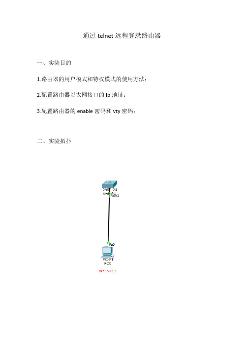
通过telnet远程登录路由器一、实验目的1.路由器的用户模式和特权模式的使用方法;2.配置路由器以太网接口的Ip地址;3.配置路由器的enable密码和vty密码;二、实验拓扑三、实验步骤第一步:按照拓扑图搭建实验环境;第二步:实验步骤;(1)步骤一:配置路由器以太网接口IP地址;1、交换机上基本操作Switch>enable \\进入全局模式Switch#conf t \\进入特权模式Switch(config)#interface vlan 1 \\进入端口Switch(config-if)#ip address 192.168.1.10 255.255.255.0 \\配置IP地址Switch(config-if)#no shutdown \\打开端口Switch(conffig-if)#exit \\回到上一步2、配置虚拟终端密码Switch(config)#line vty 0 4 \\进入vty虚拟终端Switch(config-line)#password 123 \\配置telnet密码Switch(config-line)#login \\注册Switch(config-line)#exit \\回到上一级模式下四、实验调试(1)通过telnet访问路由器在计算机配置网卡的IP地址为192.168.1.1/255.255.255.0,并打开DOS命令行窗口。
首先测试计算机和路由器的IP连通性,在进行Telnet远程登录。
如下:Ping statistics for 192.168.1.10:Packets: Sent = 4, Received = 0, Lost = 4 (100% loss),PC>ping 192.168.1.10Pinging 192.168.1.1 with 32 bytes of data:Request timed out.Reply from 192.168.1.10: bytes=32 time=0ms TTL=255Reply from 192.168.1.10: bytes=32 time=0ms TTL=255Reply from 192.168.1.10: bytes=32 time=0ms TTL=255Ping statistics for 192.168.1.10:Packets: Sent = 4, Received = 3, Lost = 1 (25% loss),Approximate round trip times in milli-seconds:Minimum = 0ms, Maximum = 0ms, Average = 0ms//以上表明计算机能ping通路由器接口fastethernet0/1的IP地址PC>telnet 192.168.1.10 //从计算机telnet路由器以太网卡上的IP地址Trying 192.168.1.10 ...OpenUser Access VerificationPassword:Switch>enablePassword:Switch#//输入vty的密码123、输入enable的密码456,能正常进入路由器的特权模式。
思科模拟器实训报告模板
一、实训背景随着信息技术的飞速发展,网络技术在各行各业中的应用日益广泛。
为了提高网络工程师的实践能力,本实训采用思科模拟器进行网络设备配置与故障排除的模拟操作,通过实际操作来加深对网络原理和技术的理解。
二、实训目标1. 熟练掌握思科模拟器的使用方法。
2. 熟悉网络设备的配置过程,包括路由器、交换机、PC等。
3. 掌握网络协议的配置,如IP地址、VLAN、RIP、OSPF等。
4. 学会网络故障的排查和解决方法。
三、实训内容1. 思科模拟器简介2. 网络设备配置3. 网络协议配置4. 网络故障排查四、实训步骤1. 环境准备- 下载并安装思科模拟器(如Packet Tracer)。
- 熟悉模拟器界面和基本操作。
2. 网络设备配置- 添加网络设备:路由器、交换机、PC等。
- 配置设备IP地址、子网掩码等网络参数。
- 配置VLAN,实现不同VLAN间的通信。
- 配置RIP、OSPF等动态路由协议。
3. 网络协议配置- 配置静态路由,实现不同网络间的通信。
- 配置NAT,实现私有网络与公网之间的通信。
- 配置DHCP,实现自动分配IP地址。
4. 网络故障排查- 模拟网络故障,如IP冲突、路由故障等。
- 使用命令行或网络诊断工具进行故障排查。
- 解决故障,恢复网络正常运行。
五、实训总结1. 实训收获- 通过本次实训,熟练掌握了思科模拟器的使用方法。
- 加深了对网络设备配置和网络协议配置的理解。
- 学会了网络故障的排查和解决方法。
2. 实训体会- 实践是检验真理的唯一标准。
通过实际操作,更加深刻地理解了网络原理和技术。
- 在实训过程中,遇到了很多困难,但通过查阅资料、请教同学和老师,最终克服了困难,提高了自己的实践能力。
3. 改进建议- 增加实训项目,提高实训难度。
- 邀请有经验的网络工程师进行现场指导,提高实训效果。
- 建立实训交流平台,方便同学之间互相学习和交流。
六、实训报告以下为实训报告示例:实训项目一:网络设备配置1. 添加网络设备:路由器、交换机、PC等。
- 1、下载文档前请自行甄别文档内容的完整性,平台不提供额外的编辑、内容补充、找答案等附加服务。
- 2、"仅部分预览"的文档,不可在线预览部分如存在完整性等问题,可反馈申请退款(可完整预览的文档不适用该条件!)。
- 3、如文档侵犯您的权益,请联系客服反馈,我们会尽快为您处理(人工客服工作时间:9:00-18:30)。
实验一:1. 口令和设备名设置添加任意的交换机或路由器,先对交换机进行操作,双击SwitchA switch>enpassword: ;第一次密码为空,直接回车switch#conf t ;进入全局配置模式switch(config)#hostname swa ;设置交换机名swa(config)#enable secret aaa ;设置特权加密口令为aaaswa(config)#enable password aax ;设置特权非密口令为aaxswa(config)#line console 0 ;进入控制台口(Rs232)状态swa(config-line)#login ;允许登录swa(config-line)#password aa ;设置登录口令aaswa(config-line)#line vty 0 4 ;进入虚拟终端virtual tty swa(config-line)#login ;允许登录swa(config-line)#password a ;设置登录口令aswa(config-line)#exit ;返回上一层swa(config)#exit ;返回上一层swa#sh run ;看配置信息swa#exit ;返回命令swa>enpassword: ;试验哪一个口令可以通过双击ROA对路由器进行与交换机类似的设置。
2. 清除口令清除交换机口令,实际中是在开机时按住交换机上的mode钮,本模拟机按Ctrl+Break清除路由器口令,参考如下:双击ROA先配置路由的特权口令:router>enpassword: ;第一次密码为空,直接回车router#conf t ;进入全局配置模式router(config)#enable secret aaa ;设置特权加密口令为aaarouter(config)#exit ;返回router#exitrouter>enpassword:aaarouter#清除口令是打开寄存器配置开关:router#reload ;重新启动,按Ctrl+Break rommon>rommon>confreg 0x2142 ;跳过配置,26xx 36xx 45xx rommon>reset;重新引导,等效于重开机router>enpassword:router#conf trouter(config)#enable secret bbb ;设置特权加密口令为aaa router(config)#config-register 0x2102 ;正常使用配置文件router(config)#exitrouter#exitrouter>enpassword:bbbrouter#=============================================================================== =================实验二:计算机与交换机IP地址设置图文件:switch1规划ip地址:PCA: 10.65.1.1PCB: 10.65.1.2SWA: 10.65.1.31.双击PCA输入用户名:root输入口令:linux设置IP :[root#PCA root]# ifconfig eth0 10.65.1.1 netmask 255.255.0.0查看IP :[root#PCA root]# ifconfig删除IP : [root#PCA root]# ifconfig eth0 10.65.1.1 netamsk 255.255.0.0 down设置网关:[root#PCA root]# route add default gw 10.65.1.9 查看网关:[root#PCA root]# route删除网关:[root#PCA root]# route del default gw 10.65.1.9 2.双击PCB输入用户名:root输入口令:linux设置IP :[root#PCB root]# ifconfig eth0 10.65.1.2 netmask 255.255.0.0设置网关:[root#PCB root]# route add default gw 10.65.1.93.双击SWA进入特权模式: switch>en进入全局配置模式: switch#conf t进入默认VLAN状态: switch(config)#int vlan 1设置ip地址和掩码: switch(config-if)#ip address 10.65.1.3 255.255.0.0 设置switch的网关: switch(config)#ip defaule-gateway 10.65.1.9查看设置: #sh run4.回PCA[root@PCA root]# ping 10.65.1.1[root@PCA root]# ping 10.65.1.2[root@PCA root]# ping 10.65.1.35.修改PCB的ip地址修改为不同网段的一个ip地址,再从PCA Ping PCB。
修改为相同网段的一个ip地址,再从PCA Ping PCB。
断开交换机与PCB计算机连线,再从PCA Ping PCB。
[root@PCA root]# ping 10.65.1.2=============================================================================== =================实验三交换机VLAN实验图文件:switch2规划ip地址PCA的ip 地址: 10.65.1.1PCB的ip 地址: 10.66.1.1PCC的ip 地址: 10.65.1.3PCD的ip 地址: 10.66.1.3SWA的ip 地址: 10.65.1.7SWB的ip 地址: 10.65.1.8SWA的f0/1~f0/3 vlan 2 ,f0/8为trunkSWB的f0/2~f0/4 valn 2 ,f0/1为trunk2.设置VLAN双击SWA: 改名Switch为SWA,建立2个vlan: 2 3SWA#vlan databaseSWA(vlan)#vlan 2SWA(vlan)#vlan 3SWA(vlan)#exitSWA#conf tSWA#sh vlan将f0/1,f0/2,f0/3 加入到vlan 2SWA(config)#int f0/1SWA(config-if)#switchport access vlan 2SWA(config-if)#int f0/2SWA(config-if)#switchport access vlan 2SWA(config-if)#int f0/3SWA(config-if)#switchport access vlan 2SWA(config-if)# Ctrl+zSWA#sh vlan与SWA类似设置SWB 的VLAN。
3.测试可通性从PCA到PCC测试:(通)[root@PCA root]# ping 10.65.1.3从PCA到PCB测试:(不通:不是一个网段,且不在一个VLAN) [root@PCA root]# ping 10.66.1.1从PCB到PCD测试:(不通:要求trunk)[root@PCB root]# ping 10.66.1.3从PCA到SWA测试:(通)[root@PCA root]# ping 10.65.1.7从PCA到SWB测试:(通)[root@PCA root]# ping 10.65.1.8从SWA到PCA测试:(通)SWA#ping 10.65.1.1从SWA到SWB测试:(通)SWB#ping 10.65.1.8再将连接两个交换机的接口设置成trunk。
SWA(config)#int f0/8SWA(config-if)#switchport mode trunkSWB(config)#int f0/1SWB(config-if)#switchport mode trunk测试从PCA和PCB到PCC、PCD、SWA、SWB的可通性。
5.装入Switch3图文件(1)都不设vlan情况下,测试连通性。
(2)设置有vlan情况下,测试连通性。
(3)使用trunk情况下,测试连通性。
=============================================================================== =================实验四:路由器的升级1. 在ROM监控模式下,使用console通过计算机的超级终端设置。
装入图文件:router1a要求路由器的console与计算机的rs232相连。
router>Ctrl+Break ;进入ROM监控状态rommon>copy xmodem:c2621.bin flash:c2621.bin ;从console升级IOS####################################################### ############################################################### ###############################################ok!rommon>dir flash:c2621.bin这种方式传送的速度比较慢,使用的是RS232串行接口的速率,波特率一般为9600,但不需要IOS的支持,在IOS损坏的情况下往往使用这种方式。
2. 在特权模式下的升级装入图文件:router1b要求TFTP Server (PCA) 接入路由器的以太口,且PCA的ip 地址与路由接口的ip地址在一个网络段。
设置TFTP的ip地址为:10.65.1.1双击HostA:login: rootpassword: linux[root#linux root]# ifconfig eth0 10.65.1.1 netmask 255.255.0.0 [root#linux root]# ifconfig ;查看IP地址双击要升级的路由器:设置与之tftp server相联接口f0/0的ip地址router(cnfig-if)#ip address 10.65.1.2 255.255.0.0router#copy tftp flash:tftp server ip address:10.65.1.1flash file name:C2621.bin####################################################### ############################################################### ###############ok!router#dir flash:c2621.bin这种方式传输的速度较快,使用的是以太网的速率。