2013增压透平膨胀机毕业设计翻译
发动机类毕业设计外文翻译
1 SummarizeOutline uses a more compact design along with the engine and has in a big way, the engine produces the waste heat density also obviously increases along with it. Some essential regions, if around a row of tyre valve radiates the question to have first to consider, the cooling system even if appears the small breakdown also possibly to create the disaster in such region consequence. The engine cooling system radiation ability generally should satisfy when the engine full load radiation demand, because this time engine produces the quantity of heat is biggest. However, when partial loads, the current capacity which the cooling system can have the power loss, which the water pumping station provides the refrigerant current capacity surpasses needs. We hoped starts the starting time to be as far as possible short. Because engine time discharges pollutant more, the oil consumption is also big. The cooling system structure has a more tremendous influence to the engine cold starting time.2 Characteristics of modern engine cooling systemModern engines series characteristic tradition cooling system function reliably protects the engine, but also should have the function which the improvement fuel economy and reduces discharges. Therefore, the modern cooling system must synthesize under the consideration the factor: Engine interior friction loss; Cooling system water pump power; Burning boundary condition, like combustion chamber temperature, complete density, complete temperature. The advanced cooling system uses systematized, the modular design method, the overall plan considered each influence factor, causes the cooling system both to guarantee the engine normal work, and enhances the engine efficiency and the reduction discharges.2.1 The temperatures set point Temperatures hypotheses firing in bursts motive operating temperature limit value are decided by a row oftire valve the peripheral region maximum temperature. The most ideal situation is according to the metal temperature but is not the refrigerant temperature control cooling system, like this can protect the engine well. Because the cooling system hypothesis cooling temperature is by the full load time most is big is the foundation, therefore, engine and cooling system in partial loads time is at not too the perfect condition, when urban district travel and low speed travel, can have the high oil consumption and discharge. Supposes the fixed point through the change refrigerant temperature to be possible to improve the engine and the cooling system in partial loads time performance. According to a row of tyre valve the peripheral region temperature limit value, may elevate either reduce the refrigerant or the metal temperature supposes the fixed point. Elevates or reduced temperature all respectively has the characteristic, this is decided the goal which achieved to the hope.2.2 Enhances the temperature Enhances the temperature to suppose the fixed-point enhancement operating temperature to suppose the fixed point is one kind of comparison the method which welcome. Enhances the temperature to have many merits, it directly affects the engine loss and the cooling system effect as well as the engine discharging formation. Will enhance the operating temperature to enhance the engine Mac reduce the engine to rub wears, reduces the engine fuel oil consumption. The research indicated that, the engine operating temperature to rubs the loss to have the very tremendous influence. Discharges the temperature the refrigerant to enhance to 150 ℃, causes the cylinder temperature to elevate to 195 ℃, the oil consumption drops 4%-6%. Maintains the refrigerant temperature in 90-115 ℃ scope, causes the engine machine oil the maximum temperature is 140 ℃, then oil consumption in partial loads time drops 10%. Enhances the operating temperature also obvious influence cooling system the potency. Enhances the refrigerant or the metaltemperature can improve the engine and disperse the steam heat transfer transmission the effect, reduces the refrigerant the speed of flow, reduces the water pump the rated power, thus reduces the engine the power dissipation. In addition, may select the different method, further reduces the refrigerant the speed of flow.2.3 Reduce the temperatures set point Reduced temperatures suppose the fixed point to reduce the cooling system the operating temperature to be possible to enhance the engine charge efficiency, reduces the inlet temperature. This to the combustion process, the fuel oil efficiency and discharges advantageously. The reduced temperature supposes the fixed point to be allowed to save the engine movement cost, enhances the part service life. The research indicated, if the cylinder head temperature reduces to 50 ℃, the ignition angle of advance may 3 ℃ A but not have the engine knock ahead of time, the charge efficiency enhances 2%, the engine operational factor improvement, is helpful to the optimized compression ratio and the parameter choice, obtains the better fuel oil efficiency and discharges the performance.2.4 Precise cooling system Precise cooling systems precise cooling system mainly manifests in the cooling jacket structural design and in the refrigerant speed of flow design. In precise cooling system, hot essential area, if around a row of tyre valve, the refrigerant has an greater speed of flow, the heat transfer efficiency is high, the refrigerant gradient of temperature changes slightly. Such effect comes from to reduce these place refrigerant channels the lateral section, enhances the speed of flow, reduces the current capacity. The precise cooling system design key lies in the determination cooling jacket the size, the choice match cooling water pump, guaranteed the system the radiation ability can satisfy when the low speed big load essential region operating temperature demand. The engine refrigerant speed of flow rangeof variation is quite big, from time 1 m/s to maximum work rate time 5 m/s. Therefore should considered the cooling jacket and the cooling system whole that, mutually supplemented, display biggest potential. The research indicated that, uses the precise cooling system, in the engine entire work rotational speed scope, the refrigerant current capacity may drop 40%. Covers the cooling jacket to the air cylinder the precise design, may make the ordinary speed of flow to enhance from 1.4m/s to 4 m/s, greatly enhances the cylinder cover or cap thermal conductivity, cylinder cover or cap metal temperature drop to 60 ℃.2.5 Divergences types cooling system Divergences types cooling system divergence type cooling system for other one kind of cooling system. In this kind of cooling system, the hine oil temperature, will cylinder cover or cap friendly cylinder body cools by respective return route, the cylinder cover or cap friendly cylinder body has the different temperature. The divergence -like cooling system has the unique superiority, may cause engine each part to suppose the fixed-point work at the most superior temperature. The cooling system overall efficiency achieves in a big way. Each cooling return route will suppose under the fixed point or the speed of flow in the different cooling temperature works, will create the ideal engine temperature distribution. The ideal engine hot active status is the cylinder head temperature lower but the air cylinder body temperature relative is higher. The cylinder head temperature is lower may enhance the charge efficiency, increases. The temperature is low also greatly may promote completely to burn, reduces CO, HC and the NOx formation, also enhances the output. The higher air cylinder body temperature can reduce the friction to lose, directly improves the fuel oil efficiency, indirectly reduces in the cylinder the peak value pressure and the temperature. The divergence type cooling system may cause the cylinder cover and the cylinder body temperaturediffers 100 ℃. The cylinder temperature may reach as high as 150 ℃, but the cylinder cover temperature may reduce 50 ℃, reduces the cylinder body to rub loses, reduces the oil consumption. The higher cylinder body temperature causes the oil consumption to reduce 4%-6%, when partial loads HC reduces 20%-35%. When the damper all opens, the cylinder cover and the cylinder body temperature supposes the definite value to be possible to move to 50 ℃ and 90 ℃, improves the fuel oil consumption, the power output from the whole and discharges.2.6 Controllable cooling system Controllable engine cooling system tradition engine cooling system belongs to the passive form, the structure simple or the cost is low. The controllable cooling system may make up at present cooling system the insufficiency. Now the cooling system design standard solves time the full load radiation problem, thus partially shoulders time the oversized radiation ability will cause the engine power waste. This to the light vehicle said especially obvious, these vehicles majority time all under the partial loads go in the urban district, only uses the partial engine power, causes a cooling system higher loss. In order to solve the engine to get down the hot question in the peculiar circumstance, the present cooling system volume was bigger, causes the evaporation efficiency to reduce, has increased the cooling system power demand, lengthened the engine during warm machine-hour. The controllable engine cooling system generally includes the sensor, the execution and the electrically controlled module. The controllable cooling system can act according to the engine working condition adjustment cooling quantity, reduces the engine power loss. In the controllable cooling system, the execution for the cooling water pump and the thermostat, generally and the control valve is composed by the electrically operated water pump, may act according to requests to adjust the cooling quantity. Temperature sensor for a system part, but rapidly bequeaths the engine hot conditionthe controller. Controllable installment, if the electrically operated water pump, may suppose the temperature the fixed point from 90 ℃ to enhance to 110 ℃, saves 2%-5% fuel oil, CO reduces 20%, HC reduces 10%. When steady state, the metal temperature ratio tradition cooling system is high 10 ℃, the controllable cooling system has the quicker response ability, may cool the temperature to maintain is supposing the fixed point ±2 ℃ the scope. From 110 ℃ drops to 100 ℃ only needs 2 s. The engine during warm machine-hour reduces 200s, the cooling system operating region draws close to the work limit region, can reduce the engine cooling temperature and the metal temperature undulation scope, reduces circulates the fatigue of metal which the hot load creates, lengthens the component life.3 ConclusionIn front of 3 conclusions introduced several kind of advanced cooling systems have the improvement cooling system performance the potential, can enhance the fuel oil efficiency and discharge the performance. The cooling system can control the nature is improves the cooling system the key, can the controlling expression to the engine structure protection essential parameter, like the metal temperature, the refrigerant temperature and the machine oil temperature and so on can control, guarantees the engine to work in the safety margin scope. The cooling system can make the rapid reaction to the different operating mode, the most earth saves the fuel, reduces discharges, but does not affect the engine overall performance. Looked from the design and the operational performance angle that, divergence type cooling and precise cooling unifies has the very good prospects for development, both can provide the ideal engine protection, and can enhance the fuel oil efficiency and discharge the nature. This kind of structure is advantageous to forming the engine ideal temperature distribution. Directly to a cylinder coveror cap row of tyre valve around the supplies refrigerant, reduced the cylinder head temperature change, causes the cylinder cover temperature distribution to be evener, also can maintains the machine oil and the cylinder body temperature at the design operating region, has a lower friction to damage the pollution withdrawal. method as follows: 1st, the cooling system function, is part of quantity of heats which absorbs the engine part carries off, guaranteed the diesel engine various components maintain in the normal temperature range. cooling system function and maintenance maintenance2nd, the cooling water should be does not contain dissolves the Xie salt the soft water, like clean river water, rain water and so on. Do not use hard water and so on the well water, water seepage or sea water, guards against produces, causes the engine to radiate not good, question occurrence and so on air cylinder heat.3rd, with the funnel when joins the cooling water the water tank, must prevent the water splashes to on the engine and the radiator, prevented on the radiator fin and the organism accumulates the dust, smears, affects the cooling effect.4th, if when the engine lacks the water causes the hyperpyrexia, cannot immediately add water, should cause the engine idling speed to revolve 10 □15 minutes, after the uniform temperature slightly reduces, slowly does not join the cooling water in the engine situation.5th, the winter, the water tank planted agent adds the hot water. After the start should surpass 40 degree-hour the slow revolution to the water temperature to be able to work. After the work had ended, must put the completely cooling water.6th, must regularly eliminate in the water tank, must frequently scour the sludge to the forced-air cooling engine radiator fin, dirty is filthy. The radiator fin cannot damage, after if damages must promptlyreplace, in order to avoid influence radiation effect.4 LathesLathes are machine tools designed primarily to do turning, facing and boring, Very little turning is done on other types of machine tools, and none can do it with equal facility. Because lathes also can do drilling and reaming, their versatility permits several operations to be done with a single setup of the work piece. Consequently, more lathes of various types are used in manufacturing than any other machine tool.The essential components of a lathe are the bed, headstock assembly, tailstock assembly, and the leads crew and feed rod.The bed is the backbone of a lathe. It usually is made of well normalized or aged gray or nodular cast iron and provides s heavy, rigid frame on which all the other basic components are mounted. Two sets of parallel, longitudinal ways, inner and outer, are contained on the bed, usually on the upper side. Some makers use an inverted V-shape for all four ways, whereas others utilize one inverted V and one flat way in one or both sets, They are precision-machined to assure accuracy of alignment. On most modern lathes the way are surface-hardened to resist wear and abrasion, but precaution should be taken in operating a lathe to assure that the ways are not damaged. Any inaccuracy in them usually means that the accuracy of the entire lathe is destroyed.The headstock is mounted in a foxed position on the inner ways, usually at the left end of the bed. It provides a powered means of rotating the word at various speeds . Essentially, it consists of a hollow spindle, mounted in accurate bearings, and a set of transmission gears-similar to a truck transmission—through which the spindle can be rotated at a number of speeds. Most lathes provide from 8 to 18 speeds, usually in a geometric ratio, and on modern lathes all the speeds can be obtained merely by moving from two to four levers. An increasing trend is to provide a continuouslyvariable speed range through electrical or mechanical drives.Because the accuracy of a lathe is greatly dependent on the spindle, it is of heavy construction and mounted in heavy bearings, usually preloaded tapered roller or ball types. The spindle has a hole extending through its length, through which long bar stock can be fed. The size of maximum size of bar stock that can be machined when the material must be fed through spindle.The tailsticd assembly consists, essentially, of three parts. A lower casting fits on the inner ways of the bed and can slide longitudinally thereon, with a means for clamping the entire assembly in any desired location, An upper casting fits on the lower one and can be moved transversely upon it, on some type of keyed ways, to permit aligning the assembly is the tailstock quill. This is a hollow steel cylinder, usually about 51 to 76mm(2to 3 inches) in diameter, that can be moved several inches longitudinally in and out of the upper casting by means of a hand wheel and screw.The size of a lathe is designated by two dimensions. The first is known as the swing. This is the maximum diameter of work that can be rotated on a lathe. It is approximately twice the distance between the line connecting the lathe centers and the nearest point on the ways, The second size dimension is the maximum distance between centers. The swing thus indicates the maximum work piece diameter that can be turned in the lathe, while the distance between centers indicates the maximum length of work piece that can be mounted between centers.Engine lathes are the type most frequently used in manufacturing. They are heavy-duty machine tools with all the components described previously and have power drive for all tool movements except on the compound rest. They commonly range in size from 305 to 610 mm(12 to 24 inches)swing and from 610 to 1219 mm(24 to 48 inches) center distances,but swings up to 1270 mm(50 inches) and center distances up to 3658mm(12 feet) are not uncommon. Most have chip pans and a built-in coolant circulating system. Smaller engine lathes-with swings usually not over 330 mm (13 inches ) –also are available in bench type, designed for the bed to be mounted on a bench on a bench or cabinet.Although engine lathes are versatile and very useful, because of the time required for changing and setting tools and for making measurements on the work piece, thy are not suitable for quantity production. Often the actual chip-production tine is less than 30% of the total cycle time. In addition, a skilled machinist is required for all the operations, and such persons are costly and often in short supply. However, much of the operator’s time is consumed by simple, repetitious adjustments and in watching chips being made. Consequently, to reduce or eliminate the amount of skilled labor that is required, turret lathes, screw machines, and other types of semiautomatic and automatic lathes have been highly developed and are widely used in manufacturing.5 Limits and TolerancesMachine parts are manufactured so they are interchangeable. In other words, each part of a machine or mechanism is made to a certain size and shape so will fit into any other machine or mechanism of the same type. To make the part interchangeable, each individual part must be made to a size that will fit the mating part in the correct way. It is not only impossible, but also impractical to make many parts to an exact size. This is because machines are not perfect, and the tools become worn. A slight variation from the exact size is always allowed. The amount of this variation depends on the kind of part being manufactured. For examples part might be made 6 in. long with a variation allowed of 0.003 (three-thousandths) in. above and below this size. Therefore, the part could be 5.997 to 6.003 in. and still be the correct size. These are knownas the limits. The difference between upper and lower limits is called the tolerance.1 概述随着发动机采用更加紧凑的设计和具有更大的比功率,发动机产生的废热密度也随之明显增大。
过程装备与控制工程毕业设计外文翻译(英文)
Dalian University of Technology
Dalian, Liaoning, China
WeiWei
School of Chemical Machinery,
Dalian University of Technology
Dalian, Liaoning, China
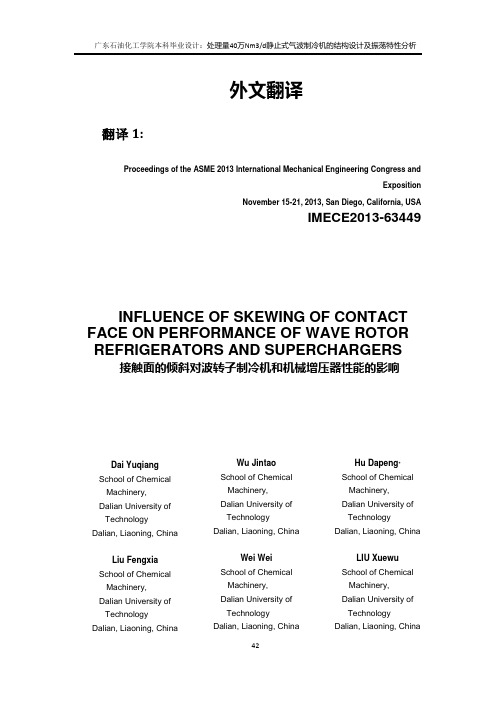
Fig.1Theoriginal wave rotor refrigerator and theexperimental arrangement
CAUSES OF SKEWING OF CONTACT FACE IN
1 Gradual Opening Process of Rotor Channels
The skewing of contact faces causes uneven distribution of velocity and large local loss. With rotation Mach number smaller than0.3,the skewing of contact face can be alleviated. To reduce the adverse influence of rotation Mach number, a smaller rotor channel width or higher rotational speed is necessary.
When a rotor channel gradually opens to the highpressure(HP) inlet port, one portion of the channels is exposed in gas streams while the others are closed by walls, which can cause boundary layer separations. In our work, two aspects of static analysis (with zeroconvectedvelocity) and dynamic analysis with constant nonzeroconvectedvelocity are performed.
增压透平膨胀机组通用使用维护说明书(杭氧产品)
增压透平膨胀机组通用使用维护说明书(杭氧产品)【关键词】增压透平膨胀机,使用维护说明书【论文摘要】增压透平膨胀机组通用使用维护说明书(杭氧产品)I.概述II.机组简介一.透平膨胀机的构造二.增压机三.供油装置四.膨胀机流量调节五.快速安全关闭六.增压气体过滤器七.增压机出口气体冷却器八.增压机回流阀III.操作说明一.开车前准备工作及检查项目二.膨胀机启动三.运行中的检视四.膨胀机停车IV.拆装说明V.维护说明VI.主要故障及其处理VII.密封器跑合本标准适用于增压机制动的,工作轮直径系列为Ø100毫米到Ø450毫米的,采用油轴承的透平膨胀机组。
I.概述本机组利用气体经膨胀机进行绝热膨胀,产生空分装置所必须的冷量,其所产生的机械功又被增压机所吸收,用以提高增压气体的压力。
机组所使用的气体应为不含有机械杂质(金属粉尘,分子筛,珠光砂粉末等)并经净化处理的干净气体。
II.机组简介机组由以下主要部分组成:(具体交货内容以合同和产品装箱清单为准。
)1.带保冷箱及底架的透平膨胀机;2.供油装置;3.增压机;4.增压机进口气体过滤器;5.增压机出口气体冷却器;机组主要组成部分除增压机气体过滤器和气体冷却器外装在一公用底架上而成一整体,用地脚螺栓固定在混凝土基础上。
必须防止周围的震动和冲击传给机组,暗转进出气管时,要保证外界作用在透平进出气管法兰上的力和力矩不超过允许值(见附图1)。
字句所需的绝热材料和润滑油由用户自备。
一.透平膨胀机(以下简称膨胀机)的构造参见膨胀机总图气体由进气管进入蜗壳,经喷嘴叶片通道进入工作轮并做机械功,然后经扩压室排出。
膨胀机流量的调节系统是依靠一安装在冷箱顶上的执行机构带动喷嘴叶片转动而改变通道截面积来实现的。
1. 膨胀机蜗壳:蜗壳直接固定在底架上并支承膨胀机主机及增压机。
蜗壳内容纳了膨胀机叶轮和喷嘴环。
在排气侧有一压圈借助一弹性压紧机构而压在喷嘴叶片上,使喷嘴叶片的端面没有间隙。
川空PLPK-833[1].3 38.5-4.8型增压膨胀机组使用维护说明书
![川空PLPK-833[1].3 38.5-4.8型增压膨胀机组使用维护说明书](https://img.taocdn.com/s3/m/1ae42d492b160b4e767fcfc5.png)
PLPK-833.3/38.5-4.8型增压透平膨胀机组 使用说明书四川空分设备(集团)有限责任公司2008年12月1概述本机组工作介质先经增压机增压,冷却后进入板式换热器,然后再进入膨胀机进行绝热膨胀降温产生液化设备所需的冷量,与此同时产生的机械功又为增压机所吸收。
2技术参数(设计工况)2.1增压机:工作介质:空气气量:50000Nm3/h±30%(0℃,0.10133MPa)进口压力:2.767MPa(A)出口压力:≥4.0MPa(A)进口温度:313K2.2膨胀机:工作介质:空气气量:50000Nm3/h±30%(0℃,0.10133MPa)进口压力:3.95MPa(A)出口压力:0.58MPa(A)进口温度:163K绝热效率:≥86%转速:24990r/min2.3仪控整定值说明:轴承油压可根据现场运转情况进行调整。
3机组简介本机组由增压透平膨胀机主机、供油系统、增压机后冷却器等组成,用地脚螺栓将其固定于混凝土基础上,同时必须防止周围的振动和冲击传给本机组,安装各进出口管道时必须防止管道重量和明显的安装应力附加在机组上。
本机组所需绝热材料和润滑油等,由用户自备。
3.1透平膨胀机:工作介质由进口管进入蜗壳,经转动喷咀再进入工作轮作功,然后经扩压室、排气管排出。
膨胀机气量调节是依靠安装在冷箱顶上的气动薄膜执行机构带动喷咀叶片转动,从而改变其通道截面积来实现,执行机构的阀杆行程反映了喷咀通道宽度的变化,阀杆总行程约为50mm,阀杆下移使喷咀通道关小,上移则开大。
3.1.1蜗壳:为不锈钢铸造结构,固定在机身上,通过机身与底座相连,蜗壳内容纳有喷咀和膨胀机叶轮。
3.1.2 转子:二端分别装有膨胀机叶轮和增压机叶轮(二者均为闭式),为一刚性转子,套装在机身轴承上。
3.1.3 轴承:前、后轴承均为径向推力联合式轴承,由进油管供给清洁而充足的润滑油,使转子能长期稳定运转,采用铂电阻温度计测量轴承温度。
毕业设计外文参考资料及译文

Fundamental information, including the effects of porosity, water-to-cement ratio, cement paste characteristic, volume fraction of coarse aggregates, size of coarse aggregates on pervious concrete strength, had been studied [3, 9−12]. However, for the reason that the porosity played a key role in the functional and structural performances of pervious concretes [13 − 14], there was still a need to understand more about the mechanical responses of pervious concretes proportioned for desired levels of porosities. Although it was possible to have widely different pore structure features for a given porosity, or similar pore structure features for varied porosities in pervious concrete, it was imperative to focus on the mechanical responses of pervious concrete at different designed porosities. However, compared with the related research on conventional concrete, very limited study had been conducted on the fracture and fatigue behaviors of pervious concrete, which were especially important for pavement concrete subjected to heavy traffic and to severe seasonal temperature change. The presented work outlined the raw materials and mixing proportions to produce high-strength supplementary cementitious material (SCM) modified pervious concrete (SPC) and polymer-intensified pervious concrete (PPC) at different porosities within the range of 15%−25%. Then, the mechanical properties of pervious concrete, including the compressive and flexural strengths, fracture energy, as well as fatigue property, were investigated in details.
外文翻译原文
ORIGINAL ARTICLEStudy on the correlated design method of plate holes for progressive dies based on functional featureZhi-Xin Jia &Hong-Lin Li &Xue-Chang Zhang &Hong-Bing Wu &Ming-Cai FangReceived:1March 2009/Accepted:12October 2009/Published online:27October 2009#Springer-Verlag London Limited 2009Abstract There are a lot of holes in a progressive die for mounting inserts,assembles,and standards.This paper gives the classification of plate holes of progressive die design according to their structural types and relationships between the correlating parts and the plate holes and describes an automated hole design system for progressive dies.Taking advantage of prebuilt design knowledge and standard parts database,this system is able to generate the correlated holes on the main plates of progressive dies,such as upper die shoes,lower die shoes,stripper plates,punch plates,die plates,punch backing plates,and die backing plates according to the inserted parts or functional assem-bles.A descriptive model is set up.The feature library technology is adopted to develop the function for the design of plate holes,which can improve the efficiency and shorten the design cycle.The hole design system is built on the top of SolidWorks,taking advantage of its built-in modules,including part,assembly,and drawing.We use progressive die for motor core as concrete examples to demonstrate the power of our system.Experimental results show that our system cannot only improve the design quality but also reduce the design time and cost.Keywords Progressive die .Hole .Correlated design .Library feature1IntroductionA progressive die is used in various industries such as aerospace,electronics,automobiles,and electrical appliances for producing sheet metal components in large quantities.As a progressive die may contain a large number of operations such as punching,blanking,bending,lancing,et al.,it has been regarded as complex and requires a great deal of expertise.Usually,the progressive design procedure is composed of two phases,operations (stamping process)planning and die structure design.Stamping process planning is to produce a flat pattern of a model of stamped metal and then plan stamping operations to obtain strip layout.The die structure design process is as follows:(1)according to the size of the strip layout,the die set is determined and the overall structure of die is generated;(2)then the inserts,punches,dies,and other forming parts are designed including positioning and locating holes;and (3)based on the specific circumstances,assistive devices are inserted such as pilot pins,ejectors,screws,dowel pins,springs,standard parts,etc.The progressive die structure design usually costs about 2/3design cycle time.There are a lot of holes in a progressive die for mounting inserts,assembles,and standards,and hole design is tedious,time-consuming,and error prone.This study is concentrated on the correlated design of holes on plates.The developments of automated,basic knowledge and intelligent design systems are studied by researchers all over the world.Cheok and Nee presented a review of research and design before 1998in the design automation of tools for metal stampings and proposed a framework for an integrated design system for progressive dies [1].Wang et al.did some research of association technology in assembly design for precision progressive die on AutoCADZ.-X.Jia (*):X.-C.Zhang :H.-B.WuNingbo Institute of Technology,Zhejiang University,1#Qianhu Road,Ningbo 315100,People ’s Republic of China e-mail:jzx@H.-L.Li :M.-C.FangSchool of Mechanical Engineering,Ningbo University,818Fenghua Road,Ningbo 315211,People ’s Republic of ChinaInt J Adv Manuf Technol (2010)49:1–12DOI 10.1007/s00170-009-2371-6[2].Kumar et al.developed an intelligent system for automatic modeling of progressive die[3].They also presented an expert system for automation of strip-layout design process using the production rule-based expert system approach of artificial intelligence on AutoCAD [4].Choi et al.developed a system written in AutoLISP on the AutoCAD for strip layout and die layout and a tool kit on the SmartCAM software for modeling and postprocessing with a PC[5–7].Based on knowledge-based rules,Kim et al.developed a system for electric product with bending and piecing operations written in AutoLISP on the AutoCAD with a PC[8].Tor et al.investigated the suitability of using a blackboard framework for stamping process planning in progressive die design[9].Li et al. adopted feature-and rule-based approach and developed an integrated modeling and process planning system for planning bending operations of progressive dies using C++and ObjectARX of AutoCAD[10].Farsi and Arezoo described a two-stage method to determine bending sequence in progressive dies[11].Chang et al.established a genetic algorithm to solve the problems of ranking the working steps in progressive dies using AutoCAD as a drawing tool[12].Taking advantage of neural network and computer-aided design(CAD)software,Pilani et al. proposed a method for automatically generating an optimal die face design based on die face formability parameters [13].Based on sheet metal operations,Singh and Sekhou developed a punch machine selection expert system,which was built in AutoCAD and used AutoLISP[14].Jiang et al. proposed a flexible and complete insert representation scheme and analyzed the complex assembly relationships and constraints between inserts and components[15]. Almost all the design systems mentioned above belong to 2D patterns.As it is not easy to find defects,check interference, modify correlated drawings,etc.in2D patterns,the development of3D software and PC technology,which describes parts in solid modeling,can dramatically help to resolve the above problems.This technique has gradually become a mainstream tool in the design industry.In recent years,more and more systems were developed on top of3D software.An automated nesting and piloting system for progressive die according to minimum scrap strategy on 3D SolidWorks was developed by Ghatrehnaby and Arezoo [16].Roh and Lee proposed a hull structural modeling system for ship design,built on top of C++and3D CAD software[17].Chu et al.developed a computer-aided parametric design system for3D tire mold production by in CATIA[18].Kong et al.developed a Windows native3D plastic injection mold design system based on SolidWorks with Visual C++[19].Lin et al.in National Kaohsiung First University of Science and Technology developed structural design systems for3D drawing dies based on functional features in Pro/E and CATIA software[20,21].Lin and Kuo also developed an integrated RE/RP/CAD/CAE/CAM system for magnesium alloy shell of mobile phone in3D software[22].Compared with the much work done in the computer-aided process planning,less work in structure design has been done. Most of the work is concentrated in the computer-aided process planning[1–4,7–13,16–19].Jia et al.presented a relationship model of structural relevance in progressive dies [23].Wang et al.discussed association technology in assembly design for precision progressive die on AutoCAD [2].Jiang et al.discussed the inserts design automation[15]. They proposed a representation scheme of inserts using an object-oriented,feature-based approach.Methods of standard part library construction and modeling methods of punches and dies were discussed in references on SolidWorks[24, 25].Zhao et al.in HuaZhong University of Science and Technology discussed correlated design of standardized parts and components in CAD system for progressive die on AutoCAD[26].For die structure design,the designer can treat each function feature as a design unit[15,20].According to the design norm and standard part library of our partner who is a progressive die company,this study describes a hole design system based on function feature in SolidWorks software.There are several commercial progressive die design systems available in the market, e.g.,progressive die wizard on NX,progressive die expert on Pro/ENGINEER, LOGPRESS on SolidWorks,TopSolid/Progress,et al. These packages can fulfill the holes design in condition that the users set up their own part library and make some customization.As the die companies are mainly small-and medium-sized enterprises,discussion with the local tool and die industry indicates that those systems are too expensive and beyond what they could afford to invest in. In addition,the commercial packages for progressive die contain“generic”design rules provided by die design textbooks,course materials,component manufacturer’s catalogues,etc.,while each die company concentrates on several classes of dies and has its own company’s specific design rules,parameters,and tooling components.Hence, the development of hole design system is necessary especially for the companies which have their own specific component library and in-house design rules.In order to make die design more flexible and efficient with higher quality,this paper proposes a computer-aided structural design system of holes on the plates of progressive die based on functional feature according to a set of design rules of a local progressive die company. Taking advantage of well-organized die design knowledge base,standard parts database,hole feature library database, and an integrated3D CAD environment,our system is ableto output hole structure correlated design for the main plates of a progressive die,such as upper die shoe,lower die shoe,punch holding plate,punch backing plate,die holding plate,and so on.Upon user’s input of strip layout, selection of die set,and design information of correlating parts,the parts are inserted into the die assemble,and correlated holes on the plates are constructed automatically.A system has been implemented which is interfaced with a parametric and feature-based CAD system,SolidWorks through C++.An example is provided to demonstrate our approach and to show its effectiveness in progressive die design.The rest of the paper is organized as follows:Section2 describes the design procedure for progressive die,hole classification,and the descriptive model for design of hole on plates for progressive dies.Section3explains the architecture of the structural design system for holes on plates and deals with the process for constructing the holes design with the help of library feature in detail.Section4 demonstrates the hole designing of a progressive die for the motor core using the proposed system.Conclusions are given in Section5.2Hole classification and the descriptive modelfor progressive diesThe structure of a progress die usually consists of an upper die shoe,a lower die shoe,a punch holder plate,upper backing plates,a lower plate,a punch backing plate,a die backing plate,and other die structure components required by each process station such as punches,dies,strip guide pins,lifters, guide posts and bushings,et al.,as shown in Fig.1.Figure1shows the structure of a typical progressive die.There are a lot of holes on the main parts such as upper die shoe,lower die shoe,punch holder plate,upper backing plates,die holder plate,punch backing plate,die backing plate,etc.,which are used for connecting, locating,and installing.The holes are different in structure,function,tolerance,and fit.Meanwhile,holes on different plates have complex correlated relations for different kinds of correlating parts or assembles,such as punches,dies,screws,pilot pin assembles,lifter pin assembles,etc.When the parameters or location is changed for the correlating parts,the size or the location must also change to fit,which cannot be defined and achieved by functions provided by general3D CAD software.Hence,the relationship among the holes,the correlating parts(or assembles),and the correlated plates must be studied on the basis of relevance.So in this paper, we first give classification for holes on plates by structure then analyze the relationship between the plate holes and associated parts and present a descriptive model.2.1Hole classification by structureBy studying the structure of the progressive dies,six types of holes are summarized according to their structure.They are through hole,step hole,blind hole,screw hole,figure hole,and combined hole.The characters of the different kinds of holes are listed below in detail.2.1.1Through holeThe hole goes through the plate.The assemble of guideposts and bushes which are employed for aligning the die set associates with the upper die shoe,the stripper holding plate, and the bottom die shoe,as shown in Fig.2.The holes on the stripper holding plate and the bottom die shoe are through holes.2.1.2Step holeThe hole has one or two steps.As shown in Fig.3,when screws and pins are employed to connect and locate two plates,the step holes are usually adopted.In Fig.1,the hole on upper die shoe is also a step hole for amounting the guide seat and the housing plate.2.1.3Blind holeThe hole is blind.Figure4shows that a slot punch is amounted on the punch holding plate by a supporting plate and a screw.A blind hole must be constructed on the stripper holding plate below in order to avoid colliding when the upper die set moves down to shear.2.1.4Screw holeThe screw hole is mainly used for screw.As shown in Fig.3,a screw hole is constructed on the connected plate.2.1.5Figure holeThe figure hole is mainly for noncircular punches and dies. As shown in Fig.4,the slot punch which is formed by wire electrical discharge machining goes through punch holding plate,stripper holding plate,and stripper plate.The contour of figure holes on the three plates is as same as that of slot punch,while the fits and tolerance are different.In addition, when the outside contour of the die inserts is noncircular, the hole on die holding plate is also regarded as figure hole, as shown in Fig.5.2.1.6Composite holeThe composite hole means that the geometric structure of the hole is complex and can be viewed as the combination(a) A set of progressive die(b) Holes on bottom die shoeHole for pilotpin components Upper die shoeHole for guideposts and bushesStripper b acking plate Stoppers Bottom die shoeHook screwHoles for hook screwHole for pilot pin components Stripper plate Die insertsBottom die shoe backing plateFig.1The structure of a typical progressive die.a A set of progressive die.b Holes on bottom dieshoeComponents for rolling ball guide post, guide cushion etc.1-guide post 2- guide bushes 3- guide bushes 4- guide seat 5-housing plate 6- inner hex screw 7- Helical-coil spring 8- steel ball retainer9- steel ball retainer 10- internal retaining ringsFig.2Assembly for guide post and bushes and the plate holesof several simple holes.For example,in order to facilitate the installation and lifting,usually four hook screws are mounted on large plates such as upper die shoe,bottom die shoe,and stripper plate,and the holes for hook screws are combined holes as shown in ually on the progressive die,typical components such as pilot pin assemble and lifter pin assemble are employed which are composed by plug screw,spring,cylinder pin,pilot,or lifter.Figure 7shows one pilot pin assemble and the holes on the correlated plates.The hole on upper die shoe is a composite hole that consists of a through hole and a screw hole.2.2Classification according to the relationship between the correlating parts and correlated plates From the points of relevance,the above-mentioned various holes associate the correlating parts (or function assemble)and the correlated plates.The relationship between the correlating parts and correlated plates can be classified into three categories,which are one to one,one to many,many to many,as shown in Fig.8.2.2.1One to oneIt means the one correlating part and the one correlated plate,as shown in Fig.8a .For example,when the hook screw is mounted on the upper die shoe or the bottom die shoe or the stripper plate as shown in Fig.6,the hook screw is the correlating part while the upper die shoe or the bottom die shoe or the stripper plate is the correlated part.The hook screw hole is the connector.This kind of relation is simple.2.2.2One to manyIt means the relation between one correlating part and a group of correlated plates,as shown in Fig.8b .This kind of relationship exists commonly such as a threaded fastener connected two or three plates and pins located two plates.There are also many such examples in relevant punch and die structures.In Fig.4,the slot punch is amounted by the supporting plate and screw.The slot punch is the correlating part that associates the punch holding plate,stripper holding plate,and stripper plate and three holes with different fits on the corresponding plate.In Fig.5,the die is the correlating part that results in threeholes,Composed dies Circular dieFig.5Die insert and relevantholesScrew and pinFig.3Step hole,screw hole,and pinholePunch1-screw 2-suporting plate 3- slot punchFig.4Figure hole,blind hole,and screwed holerespectively,on die holding plate,die backing plate,and bottom die shoe.The die is amounted on the die holding plate with an interference fit.The diameter of the circular holes on the die backing plate and the bottom die shoe is increasingly larger than the maximum contour size of the scrap in order to let the scrap drop down smoothly.2.2.3Many to manyIt indicates the relation between a group of correlating parts and several correlated plates,as shown in Fig.8c .In a set of progressive die,assembles such as guideposts and bushes,the pilot pins,and lifter pins are common components which can be standardized.In Fig.2,the assemble of guideposts and bushes composed of ten parts associates with the correlated three parts,upper die shoe,stripper backing plate,and bottom die shoe.In Fig.7,the pilot pin assemble consists of plug screw,spring,cylinder pin,pilot,and adjusting collar.The correlated parts are upper die shoe,punch backing plate,punch holding plate,stripper holding plate,stripper plate,and die holding plate.2.3The descriptive model of plate holes and associated partsFrom the analysis of the relationship of the correlating parts and the correlated plates,we can see that two conditions must be met in order to achieve the correlated structure design of holes on plates:1.The size of the hole(s)on the correlated part(s)will bedetermined by the correlating part(s).2.When location of the correlating parts is moved or the sizeof the correlating parts is edited,so too do the holes on the correlated plates.Hence,we establish a descriptive model that views the correlating parts as controller.The relationship model of associated holes is defined as follows:Class associated holes:Correlating part (one part or a functional assemble)Location points for the correlating part Correlated plates (one or a group of parts)Corresponding library features of holes (one or a group)3Construction process for correlated hole design system for progressive dieParameterized die design takes changeable sizes of die structure as parameters and then changes the die structure sizes by means of a relationship formula for the parameters so as to fulfill the design objectives.But in the relevant hole design process for progressive die,some portions of thedieHook screwFig.6Composite hole for hookscrewPilot pin assemble1-plug screw 2-spring 3-cylinder pin 4-adjusting collar 5-pilot pinFig.7Pilot pin assemble and relevant holesstructure,such as guides,punches,dies,lifters,and supporting plates,may be rather different in shape,so it is impossible to meet the design requirements by simply changing the structure size alone.Therefore,in this document,various structures of the main parts of a progressive die are partitioned into functional features,and the same functions are catego-rized into a single identical functional module.The resulting structural chart of the functional modules for holes on plates for progressive dies is shown in Fig.13.The standard punches,for example,are classified into three types:circular, rectangular,and irregular.The configuration for parts and assembly are adopted to express multiple kinds of parts and components.The library feature technology is used to accomplish the hole structure in accordance with the design criteria and design standards.3.1Application of library featureLibrary feature is modeled by using the function provided by SolidWorks software.The function let the user define customized feature by composing a group of simple feature with user-defined parameters.By extracting the feature parameters and establishing template files,user can achieve variable design for parts and assemblies.So users can quickly and easily build their own library features which can be loaded when needed.The user-defined library features are regarded as a simple feature like other features provided by SolidWorks software.When the library features is added onto the design part,they can also be parameterized in shape and location which enlarge the scope of the feature-based modeling module and simplified the modeling process effectively.b One to manyc Many to manya One to oneFig.8a One to one.b One tomany.c Many to manyFig.9Part and hole drawings for hook screw Fig.10Hook screw with three configurationsDuring the progressive die design procedure in Solid-Works software environment,different kinds of holes usually are modeled by employing the “cut-extrude ”or “hole wizard ”function.For some complex holes,e.g.,composite hole,repetitive use of “cut-extrude ”,or “hole wizard ”functions with various parameters are needed.Because there are a lot of holes on the plates and some holes are often reused,it is very convenient to establish hole feature library with various structures which can be loaded by program.As a result,the efficiency of the design is improved to a large extent.The characteristics of library feature are:1.Flexibility,the production is simple and convenient 2.The size and the structure can be self-definition 3.Positioned by setting the reference point4.The same structure with different sizes can be producedby multiple configurations Select hook screw hole as an example.The modeling processes and applications for library feature are as follows:1.Set up a desired folder for saving user-defined featuresin the design library directory.2.Draw a sketch point coincidence with the origin point,name the sketch as “locating sketch ”,then model the hole structure by employing the feature of “cut-extrude ”,“hole ”,“hole wizard ”,and so on.3.Select one or a group of features and drag them todesired folder and name the library feature with a file extension “.sldlfp ”.4.If the hole has multiple group of parameters,multipleconfigurations will be set up.Reference PlaneReference PointfeaturesFig.11Hole library feature with three configurations for hook screwFig.12Hole design system for progressive die5.When the defined library feature is loaded on a plate,the locating point on the plate is indicated and the configuration is also selected (Figs.9,10,and 11).3.2Program based on library featureSolidWorks software provides a series of redevelopment application programming interface (API)functions.The programmer can use Visual Basic,Visual C++,or other programming tools that support the object linking and embedding technology to call these API functions directly.These functions can be used to deal with the library feature by accessing “LibraryFeatureData ”.On the basis of hole library features,developer can get the parameters and configurations for each hole file with extension filename “.sldlfp ”and use them to model the plate holes which are in accordance with the design standard and criteria.This method reduces the programming workload and is more convenient and efficient than holes modeling step by step by program.So the redevelopment cycle is shortened.3.3The structure of automatic correlated hole design systemIn order to implement the hole design task according to the criteria and standards,the proposed system also allows the user to assign the type of functional features in order to replace the design with the existing functional features.Thearchitecture of the proposed system,as shown in Fig.12,includes the following:progressive die design knowledge base,holes location selector,model generator,and user interface.Each section is described below.3.3.1Standard parts and functional assembles library Standard parts and typical functional assembles Library are essential part of CAD system.Parameterized die design takes changeable sizes of die structure as parameters and then changes the die structure sizes by means of a relationship formula for the parameters so as to fulfill the design objectives.Taking the hook screw as an example,there are 12design parameters based on the design standards shown in Fig.7.Three configurations are built corresponding to three groups of parameters for hook screw part shown in Fig.8.There are 70such standard parts and 15typical functional assemblies in our system.3.3.2Holes feature libraryHoles feature library is composed of all kinds of holes which can be parameterized and located.For example,the through hole with different size can be modeled as a hole library feature which has only one changeable parameter,hole diameter.The composed hole is complex,so we deal with the model by using multiple configurations,e.g.,the hook screw hole library feature has three configurations,as shown in Fig.9.There are ten such hole library features in our system.3.3.3Progressive die design knowledge baseFor the progressive die design to be constructed with 3D standardization,it is necessary to analyze the die structure and categorize both constructional subparts and functional features of the die.Thus,the designer can systematically classify the die structure and understand the geometric operations necessary for each functional feature during the modeling processes.These data are stored in the format of a 3D solid model template and excel files.Table 1is the excel file content for the hook screw and hole in which theTable 2Pilot pin hole design table Pilot size (diameter)Pilot assemble Upper die shoeUpper backing plate Punch holding plate Stripper backing plate Stripper plate Die holding plate 3\\Pillot::config1PilotUDS(10,10)ThrouH(x1)ThrouH(x1)ThrouH(y1)ThrouH(z1)ThrouH(d1)4\\Pillot::config2PilotUDS(12,10)ThrouH(x2)ThrouH(x2)ThrouH(y2)ThrouH(z2)ThrouH(d2)5\\Pillot::config3PilotUDS(14,10)ThrouH(x3)ThrouH(x3)ThrouH(y3)ThrouH(z3)ThrouH(d3)6\\Pillot::config4PilotUDS(16,10)ThrouH(x4)ThrouH(x4)ThrouH(y4)ThrouH(z4)ThrouH(d4)Table 1Hook screw hole design table Pilot pin size (diameter)PartHoleM16\\F32HookScrew.prt::HookScrew -M16HookScrewHole_M16M24\\F32HookScrew.prt::HookScrew-M24HookScrewHole_M24M30\\F32HookScrew.prt::HookScrew-M30HookScrewHole_M30first column records the size of screw and the second column restores the hole library feature configuration, respectively.Table2is the excel file for pilot pin assemble and holes on six plates.They can be used for training new designers,inquiring about die information, as well as the compilation,modification,and debugging of programs.3.3.4Holes location selectorThis selector provides the location data for the relating parts to be inserted into the die and the holes to be modeled. There are two types of selections:One is through the point sketch,while the other one is selected from strip layout. The point sketch is composed by a series of points that are used to locate the parts such as guide post and pushing, screws,pins,and stoppers.For the punch(dies),pilot pins, lifters,and so on which are located inside the strip layout area,the location can be determined by the selection of points or contour in the strip layout.3.3.5Correlating parts selectorThis selector provides the data of type and size related to the correlating parts.Therefore,when the system is used to design correlated holes,this selector would select the type and sizes related to parts according to the design criteria. The progressive die hole design system is divided into seven main plates and ten correlating parts,as shown in Fig.13.3.3.6Model generatorThe model generator can perform3D hole modeling process and inserting relevant parts.It can be used to construct the solid model of correlated holes on corresponding plates according to the type,quantity, location,and size parameters of candidate library features by reading the excel files.Since the parameters or configurations of the holes are recognized automatically by the system rather than resulting from interactions with the user,the modeling process for hole is performed automatically.If there exists any error during the modeling processes,the design coordinator will then send an error message to the user presenting error command and circumstance.3.3.7User interfaceThe user interface is responsible for the communication between a designer and the system.The user interface of the proposed system comprises the selection of parameters and the assigned type of correlating parts.The user interface also is responsible for the detection of incorrect input data and the management of exceptional events.4Illustrative exampleThe developed system is explained with the design of a progressive die for the motor core for house appliance.Die Main Plate(Corr e lated parts)Module(Corr elating parts)Fig.13Structure charts of holes design for progressive die。
10000 m3h增压透平膨胀机设计 毕业设计说明书

前言透平膨胀机则是实现接近绝热等熵膨胀过程的一种有效机械.目前,从空调设备、低温环境模拟到空气与多组分气体的液化分离以及极低温氢、氦的液化制冷,都有透平膨胀机的实际应用.在能源的综合利用方面,透平膨胀机作为回收能量的机械也得到了广泛的应用.对于应用天燃气作为燃料的国家,利用液化天燃气的冷量是很重要的,可以利用冷热进行发电.按利用的方法有直接膨胀、直接膨胀加郎肯循环以及混合工质等三种.不管是那一种方法,都采用透平膨胀机回收功率.可见发展前景还是十分可观。
相信通过广大的科研工作人员的努力,透平膨胀机将会获得前所未有成就及更广的应用。
本毕业设计题目是10000 m3/h增压透平膨胀机设计。
限于时间和水平,本设计难免存在一些缺点和错误,敬请导师、专家批评、指正、以便修改。
编者2013年6月3日摘要透平膨胀机是通过将来自上游的高压气流膨胀机为低压气流,连续不断的转化为机械能。
高速气流使叶轮旋转,再通过由轴承支撑的转轴将机械能传递给压缩机、发电机,也可用油制动、风机制动消耗。
关键词: 透平膨胀机轴承转轴压缩机油制动AbstractTurboexpander is a machine,which continuously converts kinetic energy into mechanical energy.This is done expending the high pressure gas from upstream to a lower pressure downstream through the expander.The high pressure gas causes the radial expander to rotate .Rotation is transmitted to the shaft,which is supported by a set of bearings.The power transmitted to the shaft can be used to drive a compressor,drive an electrical generator or can be dissipated through an oil brake or air brake.Key words: Turboexpander Bearings shaft compressor brake oil目录第一章绪论 (6)§1.1透平膨胀机的应用 (6)§1.2透平膨胀机的分类 (6)§1.3国内外透平膨胀机的发展概况 (7)第二章增压透平膨胀机的设计 (11)§2.1 设计参数 (11)§2.2 透平膨胀机的热力计算 (11) (11) (11) (11) (12) (12) (15) (15) (16) (20) (27) (28) (32) (32) (35)§2.3 增压机计算 (36) (36)§2.4 主轴的设计 (41)第三章轴的强度计算及转子的临界转速 (43)§3.1轴的强度计算 (43) (43) (43) (45) (46)§3.2键的校核 (47)§3.3转子的临界转速 (48)第四章漏气损失 (52)第五章增压透平膨胀机典型结构 (54)§5.1透平膨胀机 (54) (54) (54) (55) (55) (55)§5.2离心增压机 (55) (55) (56)§5.3供油系统 (56)§5.4紧急切断阀 (54)§5.5增压机回流阀 (55)§5.6增压机后冷却器 (55)第五章计算机编程 (58)§6.1 源程序说明 (58)§6.1 C语言程序 (58)§6.2 运行结果及分析 (65)总结 (69)参考文献 (70)文献翻译 (71)致谢 (75)第一章绪论§1.1 透平膨胀机的应用总所周知,绝热等熵膨胀是获得低温的重要效应之一,也是对外做功的一个重要热力过程,而透平膨胀机则是实现接近绝热等熵膨胀过程的一种有效机械.目前,从空调设备、低温环境模拟到空气与多组分气体的液化分离以及极低温氢、氦的液化制冷,都有透平膨胀机的实际应用.在能源的综合利用方面,透平膨胀机作为回收能量的机械也得到了广泛的应用.例如高炉气透平膨胀机、石油催化裂解再生气透平膨胀机、化工尾气透平膨胀机、烟气透平膨胀机、天燃气透平膨胀机、液化天燃气透平膨胀机、液化天燃气冷热发电透平膨胀机、排热回收利用的郎肯循环透平膨胀机等.对于应用天燃气作为燃料的国家,利用液化天燃气的冷量是很重要的,可以利用冷热进行发电.按利用的方法有直接膨胀、直接膨胀加郎肯循环以及混合工质等三种.不管是那一种方法,都采用透平膨胀机回收功率.§1.2透平膨胀机的分类此外,根据工质在工作轮中的流动的方向可以有径流式、径-轴流式和轴流式之分.按照工质从外围向中心或中心向外围的流动方向,径流式和径-轴流式又有向心式和离心式的区别.事实上,由于离心式工作轮的流动损失大,因此只有向心式才有价值.如果工作轮叶片的两侧具有轮背和轮盖,则称为闭式工作轮,轮盖没有只有轮背的称为开式工作轮,轮盖和轮背都没有的,或轮背只有中心部分而外缘被切除的,则称为开式工作轮.只有在应力很大的场合才采用开式工作轮,利用外缘的切除来降低离心力.低温装置中开式工作轮的应用并不普遍.根据一台膨胀机中包含的级数多少又可以分为单级透平膨胀机和多级透平膨胀机.为了简化结构、减少流动损失,径流透平膨胀机一般都采用单级或由几台单级组成的多级膨胀.按照工质的膨胀过程所处的状态,又有气相膨胀机和两相膨胀机之分.而两相膨胀机又有气液两相、全液两相及超临界状态膨胀的区别.§1.3 国内外透平膨胀机的发展概况在透平膨胀机的发展中有较大影响的应力为1939年苏联Ⅱ.Ⅱ.Kannua 院士提出的反动式向心径流透平.它的通流部分与前一种相比,它的根本特点在于:以后的改进是局部性的.例如在密封设备中增设了一股常温的密封气,以减少冷气体的外泄漏;采用径-轴流式工作轮和闭式工作轮,以降低通流部分的流动损失;采用转动喷嘴叶片的调节方法,以提高工况时的调节性能;改进轴承结构,提高工作转速,以适应大比焓降膨胀的需要等方面.70年代以来,两相透平膨胀机的出现,指出了设计理论方面新的研究方向.由于向心径流反动式透平膨胀机的体积流量大,结构简单,工作可靠,因而首先被应用到低压空气分离和液化装置中.由于它的体积流量大,效率又得到提高,因而使一度被淘汰的空气制冷装置又获得了一定的应用.例如用于-60~-80℃的大型低温环境模拟装置,有现成压缩空气的飞机空调装置等场合.这种型式的透平膨胀机允许的级比焓降的增加,使它也伸展到中、高压的空分装置及天燃气、油田气液化装置中.此外,由于采用了高速、可靠、少污染的气体轴承,使这种透平膨胀机也有一定的适用范围.在比焓降较小而体积流量很大时,特别是在大功率能量回收装置中,则以采用轴流式透平膨胀机为宜.在比焓降很大的场合,就需要采用多级膨胀.在体积流量很小时,采用容积式膨胀机的效率就比较高.正是由于透平膨胀机具有尺寸小、重量轻、寿命长、结构简单、操作维护方便、工质少受污染等优点,和活塞式、螺杆式等所谓容积型膨胀机相比,获得了日益广泛的应用.50年代主要用于低压、大流量的场合,60年代发展到了中小流量和中高压装置中,70年代更扩展到了更小流量的低温装置和微型制冷机中.透平膨胀机已经伸展到了过去活塞膨胀机占优势的领域中.m3/h的各类全低压空分装置使用的低压空气透平膨胀机;标志产氧量为150和300m3/h中的中压空分透平膨胀机.在这同时,还发展了各种其他用途的透平膨胀机.其中有标态进气量达180000m3/h的高空环境模拟装置用透平膨胀机,也有温度低达15K的宇宙环境模拟装置用的氦气透平膨胀机,转速达12万r/min的高能物理用大型氦液化器的氦气透平膨胀机,还有用于氢、天燃气的液化以及回收能量的氢、天燃气、油田气、化工尾气、烟气、高炉气等透平膨胀机.此外,还有低比焓降的空分-氮洗联合流程用大气量、低转速的透平膨胀机和高比焓降的中压氮液化装置用分两级膨胀的中压膨胀机.在型式方面,除了应用广泛的径-轴流反动式透平膨胀机外,还出现了轴流式透平膨胀机和多级透平膨胀机.在结构方面,有半开式工作轮,也有闭式工作轮.有风机制动的,也有发电机制动的.有转动叶片调节的,也有开启喷嘴组调节的.为了配合低温装置发展的需要,有关单位也开展了一系列试验研究工作.例如试验了带固定喷嘴、喷嘴宽度调节、转动喷嘴叶片和部分进气调节等各种调节方法;试验了风机和发电机制动的性能,编制了比较符合实际的转子-轴承系临界转速的计算程序;开始了对带液的两相透平膨胀机的研究.在制造工艺方面,也先后试验成功了工作轮的精密浇铸成型、闭式工作轮的轮盖钎接工艺、工作轮的电火花加工工艺成型、气体轴承的挤压成型等新工艺.当然,与国际上的先进水平相比,我国在透平膨胀机的发展方面任存在着一定的差距.例如对流通部分的气动性能试验研究较少,设计中还缺少综合性的最优化设计方法,三元流叶轮的制造工艺也存在一定的困难,自动控制和调节的配套能力还跟不上发展的需要.随着科学技术的现代化,这些差距必将一一得到解决.第二章增压透平膨胀机的设计§2.1设计参数§2.2透平膨胀机的热力计算工质:等熵指数 k=1.4相对密度γ=1.2928 kg/m3膨胀机进气量 q v=10000 m3/h进口压力 P0=0.89Mpa进口温度 T0=175.0K出口压力 P2=0.14Mpa气体在喷嘴内的流动损失是不可避免的.不仅有气流与壁面的摩擦,还有气体内部相互间的摩擦.这就引起了气流内部的能量交换,使喷嘴出口气流的实际速度C1低于理想速度C1S,而实际的出口比焓值高于理论的比焓值.在一元流动时,这一损失通常用经验的速度系数φ来反映.因此速度系数φ是一种综合性的损失系数,它的影响因素很多,如喷嘴的结构尺寸、叶片形状、加工质量、气流参数等。
毕设翻译

Standardization and modularization driven by minimizingoverall process effortYuval Sered,Yoram Reich *School of Mechanical Engineering,Faculty of Engineering,Tel Aviv University,Tel Aviv 69978,IsraelReceived 12July 2005;accepted 17November 2005AbstractFaster product development is a major goal for companies in competitive markets.Product platform architectures support planning for addressing diverse markets and fulfilling future market desires.Applying standardization or modularization on product platform components leverages current product design effort across future products.This work introduces a method—SMDP (standardization and modularization driven by process effort)—for focusing engineering effort when applying standardization or modularization on product platform components.SMDP calculates the total design effort from current to future generations of the platform following standardization or modularization of components.By comparing the total design cost of different simulations,we can direct the design team to standardization or modularization opportunities.The contribution of this work is in using an estimation of design effort as the basis for decision in contrast to commonly used static measures of components’interactions.Such a computational approach allows conducting sensitivity studies that address the subjective nature of various estimations needed for exercising SMDP.SMDP is illustrated in a product platform design of an external-drum plate-setter for the digital prepress printing market.q 2005Elsevier Ltd.All rights reserved.Keywords:Product platform architecture;Product family;Design for variety;Design process modeling;Design structure matrix (DSM);Reward Markov chain;Genetic algorithm1.IntroductionThe increasing heterogeneity in contemporary market-places,the wider income distribution,and the slower growth within the market,are driving the need for increased product variety.Developing robust product platform architectures with modular and standardized components could enhance the ability of companies to bring products to market faster and gain an important competitive advantage.The major benefits from this are reduced design effort and time-to-market for future generations of the product [1,2].Within the growing interest in planning for product platform,there are studies that encourage the use of platform architecture in early development stages and include the consideration of marketing,design,and manufacturing issues [3].Fujita and Ishii [4]discussed design for product variety in terms of structuring essential tasks and issues associated with variety design.They tried to optimize the system structure andthe configuration of product families simultaneously.Simpson et al.[5]applied goal programming and statistical analysis techniques to provide a method that facilitates the synthesis and exploration of a common product platform concept that can be scaled into an appropriate family of products.Messac et al.[6]described the identification of common and scaleable parameters in a family of scaleable products.Sosa et al.[7]identified modular and integrative systems and Dobrescu and Reich [8]developed flexible product architecture composed of progressively shared modules.Kreng and Lee [9]described a QFD-based approach combined with linear integer program-ming for translating customer requirements and a product into recommendations for modularizing components.The last three studies employed information on components’static inter-actions.In contrast,we based our method on modeling the dynamics of design processes.We focus our attention on the use of DFV (design for variety)[1,10]as a tool for gathering design information for the product platform architecture.DFV uses specifications ‘flows’within the project,employed by two indices,the generational variety index (GVI)and the coupling index (CI),to develop a decoupled architecture that requires less design effort for follow-up products.The utilization of the above indicesisComputer-Aided Design 38(2006)405–416/locate/cad0010-4485//$-see front matter q 2005Elsevier Ltd.All rights reserved.doi:10.1016/j.cad.2005.11.005*Corresponding author.Tel.:C 9726407385;fax:C 9726407617.E-mail address:yoram@eng.tau.ac.il (Y.Reich).static without taking into account an actual analysis of the design process.In today’s products development and in particular, architecture design of products family,improved management of development processes contributes to competitive advan-tage.The key to process improvement lies in better process understanding.One can achieve this by using modeling techniques that simplify the complexity of the design process by viewing it as a set of simpler activities with interrelation-ships.This simple model could be simulated and analyzed to find process bottlenecks that can be addressed to shorten the development cycle time and reduce the design cost[11]. Gonzalez-Zugasti et al.[12]used a meta-model of the technical performance requirements and costs to optimize the design of a family of spacecraft based on a common platform.Steward’s[13]Design Structure Matrix(DSM)can be used as a model for analyzing decision-making processes.DSM provides a simple,compact,and visual representation of a complex system and supports methods for decomposition and integration.Smith and Eppinger[14]employed an extended version of the DSM,to model design as a sequential iteration approach,which involves the sequential execution of coupled tasks.Converting Martin’s CI matrix to a task-based DSM allows for studying the relationship between design tasks, arriving at alternative strategies by ordering the design tasks, evaluating design cost,and improving the overall design process.In the following sections,we introduce a method called SMDP(standardization and modularization driven by process effort),for focusing engineering effort when applying standardization or modularization on product platform com-ponents.For this purpose,SMDP is thefirst method to use dynamic simulations of design processes instead of the static information about the interface between product components (Jose and Tollenaere[15]).SMDP is a framework for integrating several former ideas into one working model. We selected particular methods for inclusions(e.g.DFV)but they are not necessary for the use of the framework.Alternative methods to collecting relevant information or modeling design processes could be exploited if found suitable.As in any integrative effort,our work proposes extensions and adjust-ments to achieve its own goals.SMDP focuses on standard-ization and modularization for minimizing design effort as a means for reducing cost and time to market.Nevertheless, other concerns such as manufacturing,marketing,service,or maintenance cost(Gershenson et al.[16];Ishii[17];Pine[2]) could be incorporated by modeling them mathematically and modifying the objective function minimized by SMDP.This modeling,however,might not be trivial and might require similar work as presented in this paper for modeling design effort.Given that many studies deal with a focused problem and propose method to address it,there is significant importance to demonstrating the need to integrate several methods for addressing a larger problem.In addition,our work provides a methodological test of the utility of previous studies and the ability to replicate their results.Referenced work such as DFV,sequential iteration,and DSM,are reviewed in order to establish their integration as part of the overall process.Simulating the product platform design and obtaining better cost considerations in planning future designs,improves decision-making.This contribution is illustrated through a genuine test case.2.The SMDP methodIn order to minimize the total design effort(DE)across the platform generations,one needs tofind the set of components to undergo standardization(I s)and the set of components to be modularized(I m),out of the group of platform components(I).Eq.(1)presents the corresponding mathematical model.min DEðI s;I mÞs:t:I s;I m4I;I s h I m Z f(1) In this work,we do not solve this problem explicitly or optimally.Rather,we provide an algorithmic heuristic solution that is computationally feasible and practically useful.The basis of SMDP is aflexible calculation of DE.Such basis allows exercising various improvement strategies based on heuristic design concepts,detailed analysis of product design knowledge,or information of customers needs.One such improvement is designingflexible product platform architecture by standardizing some components that would not require change in future platform generations or modularizing other components that could be replaced easily without influencing other platform components.SMDP conducts a simulation of components standardization and modularization,and calculates the total design effort for each simulated case.A comparison of these costs produces the right design choices.The proposed process is composed of three stages:1.Basic data collection2.Design effort estimation3.Engineering decision-making2.1.First stage—basic data collectionThe data for product platform analysis is collected during product design reviews.We use DFV as a simple and systematic means for gathering the data related to two indices:†GVI,an indicator of the redesign effort required for a component to meet the future market requirements;and†CI,that indicates the chance that a change in one component would require a change in the other.2.1.1.Determining the GVIThefirst step generates the GVI.This establishes the drivers for generational changes in the product platform.Examples of such external drivers are customer needs,reliabilityY.Sered,Y.Reich/Computer-Aided Design38(2006)405–416 406requirements,or reduced costs.The development team has to estimate qualitatively(high/medium/low)changes in these external drivers.The external drivers are translated into engineering metrics(EM)using quality function deployment (QFD)[18].For example,EM for a passenger’s car could include‘total weight’or‘maximum speed.’Subsequently,the development team has to determine target values for the EM that will take into account the expected life of the productplatform.The last step is determining the GVI matrix using a rating system to estimate the cost of changing each component to meet the future EM target values.The rating system suggested is9/6/3/1[1,10];where nine is an indication that the component needs major redesign(over50%of initial redesign cost),six indicates partial redesign(less than50%),three is small redesign(less than30%),one is minor change(less than 15%),and0means no change required.An example of a GVI matrix is illustrated in Fig.5.2.1.2.Determining the CIIntuitively,two components are considered coupled if a change made in one requires the other to change too.The strength of this coupling is estimated by developing the basic physical layout of the product and its technology in order to identify the components and their relationships.The next step lists the specificationflow supplied from each component to other components and the specifications that it receives from others.A specificationflow is a component’s engineering feature that must be passed between designers to design their respective components.We arrange theseflows in a matrix and estimate the components sensitivities for each specification change.The rating system is again9/6/3/1indicating high, medium-high,medium-low,and negligible influence,respect-ively.Zero means no specification is affecting the component.Fig.1presents the CI matrix for arranging these sensitivities and two derived indices:CI K R indicates the strength of the specifications that a component receives from other components(sum of row values for each component).CI K S indicates the strength of the specifications that a component supplies to other components(sum of column values for each component).The indices GVI,CI K R and CI K S,are depicted in Fig.2. The last step evaluates the initial work effort of each component in the current product generation.The cost is evaluated as if the design was done for thefirst time,in isolation,where all received specifications data from other components is known in advance.The output of this stage is a description of the external and internal drivers influencing each component design.2.2.Second stage—total design effort estimationThis stage collects the information for solving Eq.(1)in a heuristic manner.An outline of this stage is given in Tables1 and2while the details are given below.We iterate on the components c2I.For each component, the simulation process changes the GVI and CI indices as if the component was made standard or modular.In doing so,we collect the information for deciding whether c2I s,c2I m,or c2I K(I s g I m).For a standardization of a component,we need to design it such that changes in other components or changes in EM caused by generational variety will not impact Table1An outline of the2nd stageStandardization phaseFor each of the n components do1.Set GVI and CI K R values to zero for standardization2.Calculate total design effort DE(Table2)Modularization phaseFor each of the components not selected for standardization do1.Set CI K S values to zero for modularisation2.Calculate total design effort DE(Table2)Table2Calculation of design effort(DE)1.Calculate the probability DSM from CI matrix2.Partition the DSM using the reachability matrix algorithm to identify blocks of coupled design tasks3.Find the optimal arrangement for every coupled-block using a genetic algorithm withfitness function based on Random Walk algorithm,which givesa minimum design cost of the block tasks4.Calculate the total design effort for current and future product generations by using cost factors derived from GVI and CImatricesFig.2.The changes that affect a component[10].Y.Sered,Y.Reich/Computer-Aided Design38(2006)405–416407the component design.Therefore,standardization involves setting the GVI and CI K R of the component to zero.For a modularization of a component,we wish to design it such that changes of the component itself due to external drives will not impact other components.Modularization means setting CI K Sto zero.We evaluate the total design effort for each case.Note that if a component is eventually selected to be standardized (modularized),it would have to be designed such that its GVI and CI K R(CI K S)values are zero.Accomplishing this target by design is outside the scope of this paper.After setting the relevant matrix values to zero,we convert the CI matrix into a design task-based probability DSM,a step that will help us model the design process.In this work,we modeled the design process using the sequential iteration model,which involves the sequential execution of a coupled set of tasks[14].During the design process,tasks may be repeated.The iterative process ends when no further problems are encountered.The sequential nature of the model requires task-ordering consideration that is discussed later in the paper.A different approach can utilize a parallel iteration model, which involves executing many tasks simultaneously[19]. Theses two models are the extremes of real processes.Any other model could be implemented as well.Converting components information into design activities and their dependencies is not trivial.Additional tasks other than actual components design(e.g.integration tasks, performance tests,systems analysis,etc.)can cause different informationflows;in addition,a component’s design can be divided into several tasks.The following section discusses the simple case of one-to-one component to task mapping,where informationflow between components design tasks is proportional to informationflow between platform’s com-ponents.Additional information of other tasks and their dependencies or alternative informationflows between tasks, can be added directly to the DSM if available.Based on the coupling between components that indicate sensitivity to change,we cannot predict whether the act of iteration will occur for one task or the other.Therefore,we would have to convert the CI matrix with the sensitivity values to a probability DSM with chance values indicating the probability of an iteration to occur.We assume that a proportional relation exists between components’sensitivities and probability of redesigning coupled components when a change occurs.Other assumptions could be exercised and tested in sensitivity studies similar to those in Section 4. Logically,this claim means that:If A and B are two coupled components and the specification of component B is affected by the design of A,we can say that a change in the design of A may cause a change to the design of B.If one conducts task B beforefinishing task A,there would be some chance that task B would have to be repeated.The greater the task dependency is, the greater is the chance of task repetition hence component redesign.The matrix in Fig.3shows task A taking four units of work and task B taking seven units of work to complete.Tasks A and B are coupled such that if A is done before B(Fig.3a),and then task B is completed,there is a chance of20%that A will have to be repeated.This is because the results of B are incompatible with the previous results of A.If B is done before A(Fig.3b), then there is a40%probability that B will be repeated after task A is completed.In this case,the left tasks order is preferred over the right order since less work is done.The reason for this is because in the left matrix,not only the probability of repetition is lower,but also the task to be repeated is cheaper. The diagonal elements(P ii)show the task efforts for completion.The off-diagonal elements(P ij)represent the strength of dependency between the two tasks as the probability to be repeated[14].A blank entry in the CI matrix corresponds to a null repeat probability in the DSM.Another property of the probability DSM is a direct result of the Reward Markov Chain model’s interpretation that forces the sum of the probability(off-diagonal)elements in each column to be bounded by one,see Eq.(2).This condition is discussed later in the paper.c j;Xi s jP ij%1(2)The following process converts CI’s sensitivity values into seven strength categories and converts the number of specifications received by each component into three other different categories.The combination of these together generates the probability values for each coupling.A different conversion system could be implemented as well.A linear distribution between upper and lower bounds of the local sensitivity space(set of non-zero values in CI matrix)is used to quantify the seven levels of coupling strengths (suggested in[20],in the DeMAID tool).Wefirst calculate the mean S and standard deviation s(s)of the sensitivity space.The upper(Eq.(3))and lower(Eq.(4))bounds of the local normalized sensitivity space are defined using the mean value and standard deviation as,S upper Z S C K1sðsÞ(3) S lower Z S K K2sðsÞ(4) where K1and K2are user-prescribed values based on experience.Once these bounds are defined,associated coupling strengths can be assigned to all other couplings,see Table3(S i is the sensitivity value from CI matrix of element in the sensitivity space).The converting system for the number of specification in each coupling is high/medium/low given by a linear distribution between the maximum number of specifica-tion in one coupling and the minimum available,which is normally one specification per coupling.The combination of these two types of categories are distributed in a linear form between0.95—for the maximum case of extremely strong dependency and large number of specifications(ES/high)and0.05—for the minimum caseof Fig.3.2!2sequential iteration DSM with two possible task orderings.Y.Sered,Y.Reich/Computer-Aided Design38(2006)405–416 408extremely weak dependency and small number of specifica-tions(EW/low).The condition in Eq.(2)dictates the use of a range between0and1(in this case5%and95%)for these categories values.Still,the sum of each column in the DSM can be more then 1;therefore,we sum up every column and consider the maximum column sum to have a normalized value of0.95.All other columns will change accordingly and all matrix values will be updated to match their column sum.The resulting matrix,with tasks effort evaluation on the diagonal,is thefinal Probability DSM.In the next process step,the reachability matrix algorithm[21] is used to partition a binary DSM and identify coupled blocks. Partitioning is the process of reordering the DSM rows and columns thus eliminating the feedback marks(above the diagonal)or moving them as close as possible to the diagonal. This will cause fewer system elements to be involved in the iteration cycle resulting in a faster development process and will identify all the coupled blocks/cycles.The binary DSM is derived from the CI matrix by marking every non-zero element as1.Following this step,each coupled block is analyzed tofind the optimal way for sequencing its task.For a particular order, the sequential iteration model is interpreted as a reward Markov Chain[14].A random walk algorithm was used to simulate the reward Markov Chain of the sequential design process.The algorithm uses the DSM probability values to select the move from one node(state)to the other.For a given ordering,the algorithm calculates the cumulative work effort.Running this algorithm large number of times(in our case1000)gives a wide range of values that can be used to calculate various statistics,which are impossible to obtain when using the analytical solution of[14]. This is important since the reward Markov Chain does not behave according to normal distribution and there is no analytical way to calculate confidence intervals for making choices between different task orderings of practical processes. In contrast,the simulation allows also calculating such confidence intervals.Another benefit of the random walk over analytical solution is that it enables the use of different design efforts in recurring iterations.For example,the cost of task j in the i C1iteration can be dependent on its cost in iteration i C ji C1Z aði;jÞC j i0!aði;jÞ!1(5) The factor a(i,j)can generally be different for each task and each iteration of that task.Its value can even be greater than one if the task effort increases from one iteration to the other. Practically,it is reasonable to assume that a significant part of the study of the design task and its basic work is conducted in thefirst iteration.Therefore,most of the invested effort is utilized at thefirst time the task is addressed;on subsequent iterations,only minor changes are conducted.Therefore,a(i,j) will most likely be less than one.In our case study,we used a constant value for a(i,j).The third advantage of random walk involves the ability to introduce modification of the reward Markov Chain into the process,including parallelizing some tasks,transition between states that are not random,etc.As discussed earlier,the smaller the design total work effort is,the better is the task ordering.The problem is tofind that best order that will give the minimum cost,since the problem computational complexity increases exponentially with the coupled block size.We use a heuristic search done with genetic algorithms(GA). Its implementation requires special chromosome coding that uses direct representation of the design tasks order and two special genetic operators:a position-based crossover and an order-based mutation[22].Thefitness function for the GA is the average of total design efforts of the specific ordering,evaluated using the Random walk algorithm on a reward Markov Chain.After arranging the design tasks and calculating the total design effort for the coupled blocks,we get to thefinal step in this stage:summing the total design effort for the whole product platform through all generations:TC platform Z TC current C TC gens;(6) where TC current is the total cost of designing the current generation and TC gens is the total cost of designing the next generations.The difference between these two is that the information used for the current product design cost does not include the effects of generational variety on the total cost. TC current is given in Eq.(7)as the sum of the initial design costs of all free components(FC)that do not belong to any coupled block.And the sum of total design cost calculated for each of the coupled blocks(B).TC current ZXi2FCCost i CXj2BCost j(7)The total cost of designing the next generations is the sum of all known and calculated elements costs each multiplied by a factor that depends on internal and external drivers:TC gens ZX mi Z1Cost iðF GVI K i C F CIR K i K F GVI K i F CIR K iÞ(8) wherem j FC j C j B j the number of cost elements.F GVI K i factor that indicates component/block’s iTable3Category converting system(Rogers1994,[20])Category name Mark Calculation for adapting thecategoryCompatiblefactorExtremelystrongES S i R S upper1Very strong VS S C35K1sðsÞ%S i!S upper0.83Strong S S C15K1sðsÞ%S i! S C35K1sðsÞ0.67Nominal N S K15K2sðsÞ!S i! S C15K1sðsÞ0.5Weak W S K35K2sðsÞ!S i% S K15K2sðsÞ0.33Very weak VW S lower!S i% S K35K2sðsÞ0.17Extremely weak EW S i%S lower0.02Y.Sered,Y.Reich/Computer-Aided Design38(2006)405–416409redesign cost due to market demands forfuture generations(external drivers).F CIR K i factor that indicates component/block’s iredesign cost due to changes received fromother components(internal drivers).The GVI factor is calculated for all future generations based on the total GVI for each component.For blocks,the total GVI is calculated relative to each component’s cost in order to derive one average factor for the entire block.Since,the selected GVI rating system is not in cost terms,but means the percentage of initial redesign cost of components required to meet future EM changes,we convert these values to a range between0(no redesign)and1(100%redesign).This is based on the assumption that the redesign cost of component does not exceed the original estimations across future generations.This assumption is reasonable when dealing with product models of the same group technology where future generations of the product do not extend beyond present technology.Other estimations,if available could be incorporated as well,but they are harder to obtain practically.The CI K R factor is calculated based on the changes imposed by components that have been affected directly by external factors or indirectly by other components change due to external factors.For coupled blocks,the average CI K R values outside the block are calculated relative to block component’s cost for components that affect the block(left to the block in the partitioned CI matrix),and components that depend on the block(below the block in the partitioned CI matrix).After summing the rows of the new CI partitioned matrix we evaluate the CI K R factor for each component/block using a similar category system presented earlier in Table3. Again we convert uniformly these categories to the range between0(no redesign)and1(100%redesign).Having more information and computational time,one could calculate more accurately the total redesign cost for future generations by utilizing the exact GVI and CI matrices for each generation.This strategy is more precise since in each generation the products specifications change to meet different market needs.2.3.Third stage—comparing results for focusing effortThe above standardization simulation is done n times for all n platform components(c2I).By comparing the calculated total design effort for each simulation,we pick the components that had smaller total design costs as candidates for redesign.Since, standardization is preferredfinancially over modularization, saving manufacturing and assembly costs[10],it is conducted first.This leads to creating the set I ponents that cannot be standardized are simulated as candidates for modularization with minimal costs considerations as conducted in the standardization phase and leading to the set I m.Actual redesign techniques for applying standardization or modularization to the selected components are not discussed here but can be easily found in literature studies such as DFV [1],scaling methods for utilizing product platform common-ality[4],and others.3.Application of SMDPWe applied SMDP for designing product platform archi-tecture of laser direct imaging(LDI)plate/image-setter for the prepress market industry.For the purpose of illustration,we used a simplified example where only eight main subsystems (components)of the LDI plotter system were considered.The input of this case study was given by leading engineers that took an active part in the design and development of prepress imaging systems for market-brand names such as CreoScitex Inc.These engineers also reviewed the results of the case study and made favorable remarks regarding their resemblance to reality.This imaging system is based on external drum technology applying direct exposure of high laser power on plate panels andfilms to convert digital input intofinished panels ready to be used in standard press-printing process.A metal drum cylinder revolves about its axis allowing a fast motion imaging axis.A laser exposure head,adjacent to the drum perimeter, driven by a smooth and precise mechanism,parallel to the drum axis,allows a slow motion imaging axis,see Fig.4.The flexible plate/film is held around the drum by a registration system using edge clamps and device for punching edge holes. Load/unload system draws a plate from an automatic cassette unit or a manual tray.After the imaging process terminates,it unloads the plate to a specialfitting in the back of the machine.A computerized control system manages the process.By analyzing where the market is headed,we plan four future products ranging from a plotter designated for small printing shops to a product that meets the large high-quality press houses.The EM of the plotter change from small plate size to twice the size in future markets.The imaging quality and accuracy evolves from1600dpi in current market to 4000dpi in future products;this is done mainly by changing the writing head from visible red-laser diode650to830nm thermal imaging diode.By doing so,we allow the customer the ability to use high-quality and high-durability plates.Another change increases the productivity EM from10to25full format plates per hour in future markets;this is also achieved by going from semi automatic setting to fully automated machine.All these EM changes affect the system’s components and may require their redesign.The measures of these effects are presented in the GVI matrix,Fig.5.Looking at the total sumof Fig.4.Illustration of external drum LDI plate/image-setter technology.Y.Sered,Y.Reich/Computer-Aided Design38(2006)405–416 410。
- 1、下载文档前请自行甄别文档内容的完整性,平台不提供额外的编辑、内容补充、找答案等附加服务。
- 2、"仅部分预览"的文档,不可在线预览部分如存在完整性等问题,可反馈申请退款(可完整预览的文档不适用该条件!)。
- 3、如文档侵犯您的权益,请联系客服反馈,我们会尽快为您处理(人工客服工作时间:9:00-18:30)。
增压透平膨胀机Pressurization turbine expander增压透平膨胀机是利用膨胀机的输出功来直接将入膨胀机前的气体增压,使得入膨胀机的膨胀气体压力升高,从而达到提高膨胀机前后压差,增加单位膨胀工质的产冷量,降低膨胀量的目的,减少膨胀量就意味着减少了循环压缩功,节约了能耗,并且还避免了机械能转变成电能而导致的损失,提高了膨胀功的回收效率,可以说它比过去常采用的电机或风机作为膨胀机的制动设备更完善。
Pressurization turbine expander expander has been used before the output of the power to directly into the expander gas pressurization, makes into the expansion of the expander gas pressure, so as to improve the pressure difference before and after the expander, increase unit expansion of the refrigerating effect, reduce the expansion amount decrease inflation means that reduces the cycle compression work, save energy consumption, and also to avoid the loss of mechanical energy into electrical energy and result in improved the expansion of the recovery efficiency of work, it is often used in motor or fan as expander braking equipment more perfect.透平膨胀机是通过将来自上游的高压气流膨胀机为低压气流,连续不断的转化为机械能。
高速气流使叶轮旋转,再通过由轴承支撑的转轴将机械能传递给压缩机、发电机,也可用油制动、风机制动消耗。
Turboexpander is a machine,which continuously converts kinetic energy into mechanical energy.This is done expending the high pressure gas from upstream to a lower pressure downstream through the expander.The high pressure gas causes the radial expander to rotate .Rotation is transmitted to the shaft,which is supported by a set of bearings.The power transmitted to the shaft can be used to drive a compressor,drive an electrical generator or can be dissipated through an oil brakeor air brake.The spare parts of the turbine expander透平膨胀机的零件Bearings 轴承ACD uses hydrodynamic bearing with tilt pad journal design and tilt pad thrust faces for most compressor loaded designs.All pads are babbitted with a tin/lead materialto increase durability and increase life.These bearings provide rotor dampeningthroughout the operating range,which provides optimum reliability of the rotor dynamics.Each bearings has an imbedded RTD in the thrust face of two pads to monitor bearing temperature;one RTD is for primary use while the second is used as a backup. 在大多数带压缩机负载的设计中,ACD使用内孔和止推面均为可倾瓦的流动动力轴承.所有瓦块镶有锡合金以增加耐久力,延长寿命.这些轴承在整个运行过程中给转子提供缓冲,使转子动力性能最佳.每个轴承均带有双支(一用一备)嵌入式热敏电阻用来检测轴承温度. Shaft 轴Each shaft is made from a solid wrought bar and heat theated to assure mechanical properties at operating conditions.Each bearing journal and thrust face is dense hard chrome plate to reduce wire wooling,and therefore increased life.The wheal attachment at each shaft end is tapered to guarantee accurate alignment of the wheel for balance repeatability.The torque is transmitted through the shaft via tangs the speed pickup.Each shaft has two ground surfaces that are used to monitor the vibration.These arease are checked at final assure that the maximum mechanical and electrical runout is within 0.00025 inches.This allows use of four vibration probes during test and operation.A key phasor slot can be added to four vibration probes during test and operation.A key phasor slot can be added to the shaft at each end for the shaft seals.These hardened teeth run in close proximity to the soft babbitted seal runners.每根转子轴都有锻件经热处理精制而成,以确保运行所需机械性能.轴承轴颈和止推面均镀以硬铬以增加硬度,延长使用寿命.轴端安装叶轮的锥面确保叶轮精确配合后保持动平衡.转矩由轴端的柄脚传递.轴上有二个相距180°方位的浅凹槽用来测量转动.另外,轴上有两段测振面,在最后组装时经仔细检查,以确保径向跳动在0.00025英寸以内.在性能测试和运行时,最多可使用四个振动探头.可以选择加装相位跟踪来测量角位移.在轴二端的轴封位置加工成梳齿状迷宫密封槽,这些硬齿在设备运行时与巴氏合金密封环紧密贴合.Expander and Compressor wheels膨胀机、增压机叶轮Both the expander and compressor wheel are manufactured from a solidforging.Each forging is ultrasonically inspected and a test specimen is taken fromeach forging and checked for mechanical properties prior to manufacturing of the wheel.Each wheel is designed for a specified set of operating conditions.These conditions may require either an open or closed wheel depending on several parameters,specific speed,power,shaft speed and efficiency.Additionally each compressor wheel may require either a vaned or vaneless diffuser,depending on the specific speed,flow parameter and efficiency.The wheel design is based on providing the highest efficiency at the design conditions for both the expander and compressor wheel.Often Computational Fluid Dynamics is employed to assure the optimum design. 膨胀机和增压机叶轮均由锻件加工而成.每一锻件都经超声波检查,并从锻件上取一试样进行机械性能测试.根据不同的工况(比转速、功率、转速及效率),将叶轮设计成开式或闭式.另外,根据不同的比转速、流量、和效率,增压机叶轮可配有叶或无叶的扩压器.叶轮的优化设计基于在设计工况下获得最高效率.为了达到最佳设计值,叶轮采用三元流设计.Shaft Seals轴封ACD primarily employ’s labyrinth shaft seals for use on our machines.These labyrinth seals use a toothed labyrinth on the shaft which run in close proximity to a babbitted stationary sleeve.Seal gas is injected into a port on the stationary seal close to the expander wheel.Some of the gas flows towards the expander wheel to prevent cold process gas flows to the bearing cavity to prevent oil from entering the process gas.This gas is then vented to atmosphere through the mist eliminator on the lube oil system.On high pressure machines an intermediate port and the oil cavity to recover or vent the seal gas prior to entering the bearing cavity.The compressor end uses a similar babbitted shaft seal to prevent oil from entering the process gas,but the flow from behind the compressor is used as the seal gas and throttled across the labyrinth before entering the bearing cavity.High pressure units receive a recovery/vent port to minimize the flow of compressor gas into the bearing cavity.Each of these recovery ports are plumbed together and can be vented to therecycle compressor by the customer.ACD 机器上主要使用迷宫式轴封.这种密封采用轴上加工成型的迷宫式梳齿与巴氏合金的静环紧密贴合.密封气从静环靠近膨胀机叶轮的孔被注入到密封腔内.部分密封气流向膨胀机叶轮以阻止低温流程介质损失,其余密封气流入轴承腔以阻止润滑油进入流程介质中.密封气经润滑油系统的油雾去除排入大气.在高压膨胀机中,密封气注入孔和油腔之间设有中间孔,将密封气在进入轴承腔前回收或排空.增压机使用一个类似的巴氏合金迷宫式轴封以阻止油渗入流程介质,而来自增压机后面的气体,在进入轴承腔前,作为密封气节流通过迷宫.高压膨胀机设有一个回收或排气孔,以使进入轴承腔的压缩气流最小.经汇集后,这些回收孔里面的气体可由用户的循环增压机回收。