FAME20中文手册
Kramer AFM-20DSP 产品快速入门指南说明书
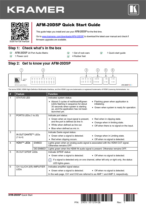
Scan for full manual AFM-20DSP Quick Start GuideThis guide helps you install and use your AFM-20DSP for the first time.Go to /downloads/AFM-20DSP to download the latest user manual and check if firmware upgrades are available.Step 1: Check what’s in the boxAFM-20DSP20 Port Audio Matrix 1 Set of rack ears1 Quick start guide1 Power cord4 Rubber feetStep 2: Get to know your AFM-20DSPThe terms HDMI, HDMI High-Definition Multimedia Interface, and the HDMI Logo are trademarks or registered trademarks of HDMI Licensing Administrator, Inc.•Green when a signal is detected. •Off when no signal is detected.If a signal is detected only on one channel, either left only or right only, the statusLED lights green.Indicates amplifier signal status:Step 3: Mount AFM-20DSPTo rack mount the machine, attach both rack ears (by removing the screws from each side of the machine and replacing those screws through the rack ears) or place the machine on a table.• Ensure that the environment (e.g., maximum ambient temperature &air flow) is compatible for the device. • Avoid uneven mechanical loading.• Appropriate consideration of equipment nameplate ratings should be used for avoiding overloading of the circuits.• Reliable earthing of rack-mounted equipment should be maintained.Step 4: Connect the inputs and outputsAlways switch OFF the power on each device before connecting it to your AFM-20DSP .For optimum range and performance use the recommended Kramer cables available at/product/AFM-20DSP . Using third-party cables may cause damage!Step 5: Connect the powerConnect the power cord to AFM-20DSP and plug it into the mains electricity.Safety Instructions (See for updated safety information)Caution:• There are no operator serviceable parts inside the unit. Warning:• Use only the power cord that is supplied with the unit.• Disconnect the power and unplug the unit from the wall before installing.• Do not open the unit. High voltages can cause electrical shock! Servicing by qualified personnel only.• To ensure continuous risk protection, replace fuses only according to the rating specified on the product label which located on the bottom of the unit.Step 6: Operate the AFM-20DSPOperate AFM-20DSP via:• Embedded web pages via the Ethernet. • RS-232 serial commandstransmitted by a touch screen system, PC, or other serial controller.Using the embedded web pagesTo route an input to an output / outputs:In the DSP Matrix page, click the lower area of cross-point buttons to connect an audio input (analog, Dante, HDMI audio signal, S/PDIF or a signal generator) to one or several outputs (analog, Dante, HDMI or S/PDIF). The button lights green. Click the dB area on a cross-point button to set the output volume.To process an input/output signal:In the DSP Main page, process each input and output audio signal and view the routing state of the matrix. Click AMP to select the amplifier audio signal.To mix the audio signals:In the DSP Mixer page, control the audio level (or mute) each input/output, define an analog input as line or mic, and so on. You can also store/recall snapshots of the current mixing setting.To define the audio and video settings:In the A/V Settings page, select the I/O port configuration, save and load system presets, define Dante and Ethernet parameters and set HDMI labels and input pattern.To define device parameters:In the Settings page, enter the device name, Ethernet settings, firmware upgrade, date and time settings or perform a factory reset.。
Model 4020中文操作手册

4 操作本部分介绍如何设置和操作Model 4020分析仪。
4.1和4.5介绍准备步骤,从4.7开始介绍实际的操作。
4.2 事先断电检查在开始使用分析仪之前应断电检查,检查内容如下:1.看样气和载气的安装是否与安装和应用部分的要求一致(chapter 3)。
保证这些气体的安装在正确的位置,并且正确地接到分析仪的后部。
2.检查电路安装是否与安装部分(chapter 3)和输入输出表中的用法说明一致。
3.检查电路板和电缆/线的安装/连接是否正确。
4.确定记录器和报警器安装正确。
4.3 进入操作状态1.打开电源2.完成下述的空气调节之后,需要预热至少两个小时(加热传感器和取样系统)。
预热时间出厂时已经由软件设置好。
预热时,禁止点火。
4.4 气体调节4.4.1 空气1.调节空气瓶上的减压阀,将空气的压力调节到30psig。
2.调节仪器上的空气减压阀,将空气压力调节到指定的空气压力。
等空气流过传感器和预热完成之后,调节其他气体。
4.4.2 样气样气瓶压力调节到30psig(或者与样气压力匹配的压力),调节仪器上的样气调节阀,将样气压力调节到指定的样气压力。
4.4.3 标气1.将标气通入分析仪。
在样气和标气之间需要一个三通阀来实现二者间的切换。
2.将标气压力调节至30psig或者与样气压力匹配的压力。
3.调节仪器的样气压力,直到指定的样气压力,同时,旁路流量计读数为0.5到1.0SCFH。
4.4.4 燃烧气1.打开气瓶上的主阀门,将气瓶压力调节到30psig(或与样气压力匹配的压力)。
2.缓慢地打开气瓶上第二个阀门,以避免仪器上燃烧气减压阀受到过大的压力冲击。
注:LED红灯灭后,才能调节燃烧气。
4.5 点火当预热倒数计时器读数为零(传感器预热计时器)时,黄色加热器指示灯闪(表示温度控制其将温度保持在设置点上),红色点火失败指示灯亮。
预热完成后,4020会自动尝试点火,如果自动点火失败,一段时间后仪器会重新尝试点火,如果五次自动点火失败,就会显示一个点火失败信息。
ME-20中文说明书

y 清洁本设备之前,请关闭电源并从插 座上拔下 AC 适配器连接线。
y 若怀疑您的地区可能发生雷击时,请 将电源插头拔掉。
y 如果使用不当,电池会发生爆炸或漏 液以及造成损害。为了使用安全,请 阅读并遵循以下事项(11 页) y 严格遵循电池安装操作说明,并确 认电池的正负极点是否正确。 y 避免将新旧电池混和使用,也请不 要将不同类型的电池混和使用。 y 设备如在一段时期内不使用,请将电池取出。 y 如果电池发生漏液,请使用柔软的擦布或纸 巾将电池槽中的液体擦干净,并装入新的电 池。为了避免液体腐蚀您的皮肤,请不要让 漏液接触到您的手或皮肤。千万小心不要使 漏液接触到眼睛,如果液体进入眼睛,立即 使用清水进行冲洗。 y 不要将电池与金属物体放在一起,如圆珠笔、 项链或发卡等。
y 与其他设备进行连接时,请关闭本设备的电 源。这样可以避免设备故障和音箱或其他设 备的损坏。
放置场所
y 请不要将本机直接曝晒在阳光下,或放在 热源旁边,或是放在密闭的车内空间,以 及其它高温物体旁。过高的温度容易造成 机体变形及变色。
y 请勿将橡胶、乙烯基等或类似物品长期放 置于设备上。这类物品可能会导致设备褪 色或外观的损坏。
y 使用后的电池必须遵循您居住区域的 安全处理条例进行处置。
上海乐兰电子有限公司
3
重要注意事项
除了阅读第 2-3 页的“安全使用本设备”,请阅读下文,并遵照执行。
电力供应:使用电池
y 请勿将本设备与其他由逆变器控制的设备 (如冰箱、洗衣机、微波炉或空调)或带有电 机的电器设备共用一个电源输出口。由于电 器设备使用方法不同,产生的电源噪音可能 会导致本设备故障或产生噪音。若无法使用 独立的电源插座,请在本设备与电源输出口 之间安装一个电源噪音滤波器。
PMEG2020AEA中文资料
handbook, halfpage
200
MDB824
(1) (2) (3) (4)
Tamb = 125 °C. Tamb = 85 °C. Tamb = 25 °C. Tamb = −40 °C.
Cd (pF) 150
Fig.3
Reverse current as a function of reverse voltage; typical values.
100
50
0 0 5 10 15 V (V) 20 R
f = 1 MHz; Tamb = 25 °C.
Fig.4
Diode capacitance as a function of reverse voltage; typical values.
2004 Feb 26
4
Philips Semiconductors
(4)
(1) (2) (3) (4)
Tamb = 125 °C. Tamb = 85 °C. Tamb = 25 °C. Tamb = −40 °C.
10−5
Fig.2
Forward current as a function of forward voltage; typical values.
0 5 10 15 VR (V) 20
Product specification
20 V, 2 A very low VF MEGA Schottky barrier rectifier in SOD323 (SC-76) package
LIMITING VALUES In accordance with the Absolute Maximum Rating System (IEC 60134) SYMBOL VR IF IFRM IFSM Tstg Tj Tamb PARAMETER continuous reverse voltage continuous forward current repetitive peak forward current non-repetitive peak forward current storage temperature junction temperature operating ambient temperature Tsp ≤ 55 °C tp ≤ 1 ms; δ ≤ 0.25 t = 8 ms square wave CONDITIONS − − − − −65 − −65
捷远梦之梦20L微波炉用户指南说明书

SAVE THESE INSTRUCTIONS CAREFULLYRead these instructions carefully before using your microwave oven,and keep it carefully.If you follow the instructions, your oven will provide you with many years of good service.MODEL:BM20LNB /BM20LIXSpecifications(a) Do not attempt to operate this oven with the door open since this canresult in harmful exposure to microwave energy. It is important not to break or tamper with the safety interlocks.(b) Do not place any object between the oven front face and the door or allow soil or cleaner residue to accumulate on sealing surfaces.(c) WARNING: If the door or door seals are damaged, the oven must not be operated until it has been repaired by a competent person.ADDENDUMIf the apparatus is not maintained in a good state of cleanliness, its surface could be degraded and affect the lifespan of the apparatus and lead to a dangerous situation.PRECAUTIONS TO AVOID POSSIBLE EXPOSURE TO EXCESSIVE MICROWAVE ENERGY230V~50Hz 1250W 800W 20L 245mm Model:Rated Voltage:Rated Input Power(Microwave):Rated Output Power(Microwave):Oven Capacity:Turntable Diameter:External Dimensions:Net Weight:M Approx 1.kg 594X344X388mmB 20LNB/BM20LIX 45To reduce the risk of fire, electric shock, injury to persons or exposure to excessive microwave oven energy when using your appliance, follow basic precautions, including the following:1. Warning: Liquids and other foods must not be heated in sealed containers since they are liable to explode.2. Warning: It is hazardous for anyone other than a competent person to carry out any service or repair operation that involves the removal of a cover which gives protection against exposure to microwave energy.3. This appliance can be used by children aged from 8 years and above and persons with reduced physical, sensory or mental capabilities or lack of experience and knowledge if they have been given supervision or instruction concerning use of the appliance in a safe way and understand the hazards involved.Children shall not play with the appliance.Cleaning and user maintenance shall not be made by children unless they are older than 8 and supervised.4. Keep the appliance and its cord out of reach of children less than 8 years.5. Only use utensils that are suitable for use in microwave6. The oven should be cleaned regularly and any food deposits should be removed.7. Read and follow the specific:"PRECAUTIONS TO AVOID POSSIBLE EXPOSURE TO EXCESSIVE MICROWAVE ENERGY".8. When heating food in plastic or paper containers,IMPORTANT SAFETY INSTRUCTIONS WARNING oven .skeep an eye on the oven due to the possibility of ignition.9. If smoke is emitted, switch off or unplug the appliance and keep the door closed in order to stifle any flames.10. Do not overcook food.11. Do not use the oven cavity for storage purposes.Do not store items, such as bread, cookies, etc. inside the oven.12. Remove wire twist-ties and metal handles frompaper or plastic containers/bags before placing them in the oven.13. Install or locate this oven only in accordance with the installation instructions provided.14. Eggs in the shell and whole hard-boiled eggs should not be heated in microwave ovens since they may explode, even after microwave heating has ended.15.This appliance is intended to be used in household and similar applications such as:-staff kitchen areas in shops, offices and other working environments;-by clients in hotels, motels and other residential type environments;-farm houses;-bed and breakfast type environments.16. If the supply cord is damaged, it must be replaced by the manufacturer, its service agent or similarly qualified persons in order to avoid a hazard.17. Do not store or use this appliance outdoors.18. Do not use this oven near water, in a wet basementor near a swimming pool.19. The temperature of accessible surfaces may be high when the appliance is operating. The surfaces are liable to get hot during use. Keep cord away from heatedsurface, and do not cover any vents on the oven.20. Do not let cord hang over edge of table or counter.21. Failure to maintain the oven in a clean conditioncould lead to deterioration of the surface that could adversely affect the life of the appliance and possibly result in a hazardous situation.22.The contents of feeding bottles and baby food jarsshall be stirred or shaken and the temperature checked before consumption, in order to avoid burns.23. Microwave heating of beverages can result indelayed eruptive boiling, therefore care must be taken when handling the container.24.The appliance is not intended for use by persons (including children) with reduced physical, sensory or mental capabilities, or lack of experience and knowledge, unless they have been given supervision or instruction concerning use of the appliance by a person responsible for their safety.25.Children should be supervised to ensure that they do not play with the appliance.26.The appliances are not intended to be operated by means of an external timer or separate remote-control system.27. Accessible parts may become hot during use.Young children should be kept away.28.Steam cleaner is not to be used.29.During use the appliance becomes hot. Care shouldbe taken to avoid touching heating elements inside the oven.30.Only use the temperature probe recommended forthis oven.(for ovens provided with a facility to use atemperature-sensing probe.)31.WARNING: The appliance and its accessible parts become hot during use. Care should be taken to avoid touching heating elements. Children less than 8 years of age shall be kept away unless continuously supervised.32.The microwave oven must be operated with the decorative door open.(for ovens with a decorative door.)33.Surface of a storage cabinet can get hot.34.The microwave oven is intended for heating food and beverages.Drying of food or clothing and heating of warming pads,slippers,sponges,damp cloth and similar may lead to risk of injury,ignition or fire.READ CAREFULLY AND KEEP FOR FUTURE REFERENCETo Reduce the Risk of Injury to Persons Grounding InstallationDANGERElectric Shock Hazard Touching some of the internal components can cause serious personal injury or death. Do not disassemble this appliance. WARNINGElectric Shock Hazard Improper use of the grounding can result in electric shock.Do not plug into an outlet until appliance is properly installed and grounded.This appliance must be grounded. In the event ofan electrical short circuit, grounding reduces therisk of electric shock by providing an escape wirefor the electric current.This appliance is equipped with a cord having a grounding wire witha grounding plug. Theplug must be plugged into an outlet that is properly installed and grounded.Consult a qualified electrician or servicemanif the grounding instructions are not completely understood or if doubt exists as to whether the appliance is properly grounded.If it is necessary to use an extension cord, use onlya 3-wire1. A short power-supply cordis provided to reduce the risks resulting from becoming entangled in or tripping over a longer cord.cord is used:1)The marked electrical rating of the cord set or extension cord should be at least as great as the electrical rating of the appliance.2)The extension cord must bea grounding-type 3-wire cord.3)The long cord should be arranged so that it will not drape over the counter top or tabletop where it can be pulled onby children or tripped over unintentionally.cord.extension2. If a long cord set or extensionCLEANINGBe sure to unplug theappliance from thepowersupply.1. Clean the cavity of the oven after using with a slightly damp cloth.2. Clean the accessories in the usual way in soapy water.3. The door frame and seal and neighbouring parts must be cleaned carefully with a damp cloth when they are dirty.4. Do not use harsh abrasive cleaners or sharp metal scrapersto clean the oven door glass since they can scratch the surface, which may result in shattering of the glass.5. Cleaning Tip---For easier cleaning of the cavity walls that the food cooked can touch: Place half a lemon in a bowl, add 300ml (1/2 pint) water and heat on 100% microwave power for 10 minutes. Wipe the oven clean using a soft, dry cloth.UTENSILSCAUTIONPersonal Injury HazardIt is hazardous foranyone other than acompentent persontocarry out any service or repair operation that involves the removalof a cover which gives protection against exposure to microwave energy.Utensil Test:1. Fill a microwave-safe container with 1 cup of cold water (250ml) along with the utensil in question.2. Cook on maximum power for 1 minute.3. Carefully feel the utensil. If the empty utensil iswarm, do not use it for microwave cooking.4.Do not exceed 1 minute cooking time.See the instructions on "Materials you can use in microwave oven or to be avoided in microwave oven." There may be certain non-metallic utensils that are not safe to use for microwaving. If in doubt, you can test the utensil in question following the procedure below.Materials you can use in microwave ovenUtensilsRemarks Aluminum foil Shielding only. Small smooth pieces can be used to cover thin parts ofmeat or poultry to prevent overcooking. Arcing can occur if foil is tooclose to oven walls. The foil should be at least 1 inch (2.5cm) away from oven walls.Follow manufacturer’s instructions. The bottom of browning dish must beat least 3/16 inch (5mm) above the turntable. Incorrect usage may causethe turntable to break.Microwave-safe only. Follow manufacturer's instructions. Do not usecracked or chipped dishes.Always remove lid. Use only to heat food until just warm. Most glass jarsare not heat resistant and may break.Heat-resistant oven glassware only. Make sure there is no metallic trim.Do not use cracked or chipped dishes.Follow manufacturer’s instructions. Do not close with metal tie. Makeslits to allow steam to escape.Use for short–term cooking/warming only. Do not leave oven unattended while cooking.Use to cover food for reheating and absorbing fat. Use with supervisionfor a short-term cooking only.Use as a cover to prevent splattering or a wrap for steaming.Microwave-safe only. Follow the manufacturer’s instructions. Should belabeled "Microwave Safe". Some plastic containers soften, as the foodinside gets hot. "Boiling bags" and tightly closed plastic bags should beslit, pierced or vented as directed by package.Microwave-safe only. Use to cover food during cooking to retainmoisture. Do not allow plastic wrap to touch food.Thermometers Microwave-safe only (meat and candy thermometers).Wax paperUse as a cover to prevent splattering and retain moisture.Browning dish Glass jars Glassware Oven cooking bags Paper plates and cups Paper towels Parchment paper Plastic Plastic wrap Dinnerware Materials to be avoided in microwave ovenUtensilsRemarks Aluminum trayFood carton withmetal handleMetal or metal-trimmed utensilsMetal twist tiesPaper bagsPlastic foamWood Metal shields the food from microwave energy. Metal trim may cause arcing.May cause a fire in the oven.Plastic foam may melt or contaminate the liquid inside when exposed to high temperature.Wood will dry out when used in the microwave oven and may splitor crack.May cause arcing. Transfer food into microwave-safe dish.May cause arcing. Transfer food into microwave-safe dish.May cause arcing and could cause a fire in the oven.B) Turntable shaftC) Turntable ring assemblyD) Glass trayE) Observation windowF) Door assemblyG) Safety interlock systemASETTING UP YOUR OVENNames of Oven Parts and AccessoriesRemove the oven and all materials from the carton and oven cavity.Your oven comes with the following accessories:Glass tray 1Glass tray a. Never place the glass tray upside down. The glasstray should never be restricted.b. Both glass tray and turntable ring assembly mustalways be used during cooking.c. All food and containers of food are always placedon the glass tray for cooking.d.If glass tray or turntable ring assembly cracks orbreaks, contact your nearest authorized servicecenter.Turntable InstallationInstallation and connection1.This appliance is only intended for domestic use.2.This oven is intended for built-in use only. It is not intended for counter-top use or for use inside a cupboard.3. Please observe the special installation instructions.4.The appliance can be installed in a 60cm wide wall-mounted cupboard(at lease 55cm deep and 85cm off the floor).5.The appliance is fitted with a plug and must only be connected to a properly installed earthed socket.6.The mains voltage must correspond to the voltage specified on the rating plate.7.The socket must be installed and connecting cable must only be replaced by a qualified electrician. If the plug is no longer to accessible following installation, an all-pole disconnecting device must be present on the installation side with a contact gap of at lease 3mm.8.Adapters, multi-way strips and extension leads must not be used. Overloading can result in a risk of fire.The accessible surface maybe hot during operation.Please noteElectrical connectionThe oven is fitted with a plug and must only be connected to a properly installed earthed socket. The socket must only be installed and the connecting cable must only be replaced by a qualified electrician, and in accordance with the appropriate regulations.If the plug is no longer accessible following installation, an allĆpole isolating switch must be present on the installation side with a contact gap of at least 3 mm.The fitted cabinet must not have a back wall behind the appliance.Minimum installation height: 85 cm.Do not cover ventilation slots and suction holes.Note:Do not trap or bend the power cable.Installation InstructionsPlease Read the Manual Carefully Before InstallationA. Built-in furniture380+234050380+2Note:The bracket and bottom caninet template are needed when installating in installation.both sB.Prep are the cab i inetput the template on the bottom plane of cabinet.1. Read the instruction on the BOTTOM CANINET TEMPLATE ,2. Make the marks on the bottom plane of cabinet according to marks"a" of of the template3. Remove the bottom cabinet template and fix the bracket w ith screw A.BracketScrew A.Install the oven4. Install the oven to the cabinet- Make sure the back of the oven is locked by bracket.- Do not trap or kink the power cord.bracket5. Open the door, fix the oven to the cabinet wi th Screw B, at the installa tion hole. Then fix the Trim-kit plastic cover to the installation hole.Screw BInstallation HoleControl PanelOperation Instructions3) Press " ", the minute figures will flash.3) Press " " to confirm, and the screen displays "P 80".5) Press " " to start cooking .1. Clock SettingWhen the microwave oven is electrified, the LED will display "0:00", buzzer will ring once.1) Press "" twice to select clock function, the hour figures will flash.5) Press " " to finish clock setting. ":" will flash, and the time will light.Note : the step quantities for the adjustment time of the coding switch are as follow: 0---1 min : 5 seconds 1---5 min : 10 seconds 5---10 min : 30 seconds 10---30 min : 1 minute power.Note: 1) 2) During the process of clock setting, if you press " ", the oven will go back to the previous status automatically.2. Microwave Cooking" the LED will display "P100".Press " ""P30" or "P10" will display for each added press. Then press" "Example: If you want to use 80% microwave power to cook for 20 minutes, you can operate the oven as the following steps.Start/+30Sec./Confirm Kitchen Timer/Clock Start/+30Sec./Confirm Stop/Clear Start/+30Sec./ConfirmThe clock will not work if it is not set when powered.Kitchen Timer/ClockKitchen Timer/Clock Microwave3) Press " " to start defrosting.1) In waiting state, Press " " to start cooking with 100% power,each added press will increase 30 seconds cooking time up to 95 minutes.2) In microwave cooking or time defrost state, each press of" " can increase 30 seconds of cooking time. microwave power, then press " " to start cooking.Start/+30Sec./Confirm Start/+30Sec./Confirm Start/+30Sec./ConfirmStart/+30Sec./Confirm" to confirm setting.(4) When the kitchen time is reached, clock indicator will go out. The buzzer will ring 5 times. If the clock be set(24-hour system), LED will display the current time.Note: The kitchen Time is differ from 24-hour system,Kitchen Timer is a timer.3) Press " " to start defrosting.The defrost power is P30 , and it cannot be changed.Start/+30Sec./Confirm once, LED will display 00:00.3. Quick Start5. Defrost By Timefish,beverage and popcorn.4) Press " " to start cooking.Start/+30Sec./Confirm vegetable,pasta, potato,7) Press " " to start cooking, and buzzer will sound once for the first section, defrosting time counts down; buzzer will sound once again entering the second cooking. when cooking finish, buzzer sounds five times.3) Press " " once, the screen display "P100".5) Press " " to confirm, and the screen displays "P 80".At most 2 sections can be set for cooking. In multi-section cooking, if one section is defrosting, then defrosting shall be placed in the first section.Example: If you want to defrost food for 5 minutes and then cook with 80% microwave power for 7 minutes, operate it as the following:Start/+30Sec./Confirm Start/+30Sec./Confirm7. Multi-section cookingMicrowaveAuto MenuMenu Weight DisplayA-1Pizza200g 200400g 400A-2 Meat 250g250 350g 350 450g450A-3 Vegetable 200g200 300g300 400g400A-4 Pasta 50g (with water 450g) 50 100g(with water 800g) 100A-5 Potato 200g 200 400g 400 600g 600A-6 Fish 250g 250 350g 350 450g 450A-7 Beverage 1 cup (120ml) 12 cup (240ml) 23 cup (360ml) 3A-8 Popcorn 50g 50 100g 10021(1) In states of microwave cooking, press " ", be displayed for 3 seconds. After 3 seconds, the oven will turn back to the former state;(2) In cooking state, press " " to inquire the time and the time will display for 3 seconds.1Lock: In waiting state, press " " for 3 seconds, there will be a long beepdenoting entering the children-lock state and the current time will diplay if the time has been set, otherwise, the LED will display " ".Lock quitting: In locked state, press " " for 3 seconds, there will be a long "beep" denoting that the lock is released.Stop/Clear Stop/ClearKitchen Timer/ClockMicrowave 9. Inquiring Function0. Lock-out Function for Childrenthe current power willTrouble shootingAccording to Waste of Electrical and Electronic Equipmenttreated. If at any time in future you need to dispose of thisproduct please do NOT dispose of this product with householdwaste. Please send this product to WEEE collecting pointswhere available.22PN:16170000A23116。
20 20MPI Flame Detector说明书

20/20MPIMain Features• Long distance Flame Detection (up to 140ft / 43m)• Large Field of View (100° horizontal / 90° vertical)• Highest immunity to false alarms• Output options (two models):– Alarm and Fault relay outputs (4 wire)or– Stepped mA output (3 wire source)• RS-485 Modbus Compatible• Automatic and Manual Built-In-Test (BIT)• 3 Year WarrantyWith its lightweight housing and low power consumption,the 20/20MPI provides a cost effective solution, speciallysuited to indoor applications such as transport terminals,storage areas, industrial kitchens and historical andcultural sites with large open areas, providing an efficientalternative smoke and heat detectors often prove to beineffective.The 20/20MPI is a compact, lightweight, high performanceIR3 detector with a new design for retail use based onindustrially proven IR3 technology. The 20/20MPI retainsall the benefits of IR3 technology, including long distancedetection and the highest immunity to false alarms.A compact,lig h tweig h t,high performanceIR3 Flame Detectorbased on Spectrex’s proven industrialIR3 technologyAIRPORT TERMINALSAirport terminals situated in dense cities often have large halls, accompanied by retail, food and beverage outlets, each with their fire risks, which don’t have full fire protection coverage. With the structure’s size and complex design, fires are often difficult to detect and larger fires are less common due to the large air intake.TRAIN STATIONS AND TERMINALSTrain stations and terminals often have large atria containing food and beverage outlets which have large air intake and often have little fire protection coverage. Additionally, within these areas, electricity and fuel are present, increasing the chances of ignition.STORAGE AREASA wide range of substances are stored within open or closed storage facilities, part of which can be dangerous or flammable, creating a greater fire hazard than usual.ARCHIVESA large amount of paper work collecting dust poses potential fire hazards that require monitoring.MALLSWith over 1,000 fire events taking place annually within the retail industry, it is imperative that the large open areas with high ceilings found in shopping malls have full fire protection coverage in order to avoid damage to assets and personnel.HOSPITALSHospitals consist of large open spaces and confined rooms, all of which contain a wide variety of contents that pose hazards. Cooking and heating equipment, as well as electrical distribution, lighting and medical equipment such as oxygen tanks are found throughout hospital buildings and are all potential fire risks which should be protected against.Main ApplicationsCAR PARKING TOWERS AND GARAGES Areas intended for vehicle storage or maintenance contain large amounts of fuel and fumes within an enclosed space, posing a fire hazard that must be monitored.PUBLIC BUILDINGSPublic buildings often house governmental offices and more, requiring excellent fire protection in order to prevent damage to assets and personnel in any potential fire.BANKS AND OFFICESBanks and offices face common fire hazards with large open areas, coupled with large amounts of paperwork and a large volume of people constantly passing through.HISTORICAL AND CULTURAL SITES Historical, cultural or national sites often contain irreplaceable assets, alongside flammable materials. A fire within these areas which were not designed with safety in mind would cause irreversible damage. AIRCRAFT HANGARSLarge open floor areas with high roofs provide a suitable area for aircraft storage and repair. However, the large quantities of liquid jet fuel and risk of spill, coupled with maintenance activities provide potential ignition sources which is complicated by aircraft wing obstructions. CABLE TUNNELSCable tunnels play an essential role in every industrial company. Any fire damage to the cables puts entire production areas out of action. As the cable tunnel environment deteriorates with time, cable insulation performance decreases, leaving an increased heating value and greater risk of tunnel fires and detection of these fires is essential in order to prevent further damage.Main ApplicationsGENERAL SPECIFICATIONSSpectral Response Three IR Bands ft m ft mDetection Range n-Heptane 140 43 Methanol 100 30*Highest sensitivity setting Gasoline 140 43 IPA (Isopropyl Alcohol) 115 35for 1 ft2 (0.1m2) pan fire Diesel Fuel 100 30 Methane* 40 12JP5 100 30 LPG (Propane)* 40 12Kerosene 100 30 Polypropylene Pellets 50 15Alcohol (Ethanol) 100 30 Office Paper 50 15*20" (0.5m) long 8" (0.2m) width plume fireResponse Time Typically 5 secondsAdjustable Time Delay Up to 30 secondsSensitivity Range 4 sensitivity ranges for 1 ft2 (0.1m2) gasoline pan fire: 35 ft (11m) up to 140 ft (43m) Field of View100° horizontal, 90° verticalBuilt-in-Test Manual and Automatic BITTemperature Range Operating: -40°F (-40°C) to +160°F (+70°C)Storage: -40°F (-40°C) to +160°F (+70°C)Humidity Up to 95%ELECTRICAL SPECIFICATIONSPower Supply Operating Voltage: 18-32 VDCPower Consumption20/20MPI-R at 24V DC: Max. 15mA at NormalMax. 25mA at Alarm20/20MPI-M at 24V DC: Max. 16mA at NormalMax. 36mA at AlarmElectrical Connection M20 Gland ConnectionElectrical Input Protection Per EN54-10Electromagnetic Compatibility EMI/RFI protected CE Marked per EN50130-4OUTPUTS20/20MPI-R Relays Alarm and FaultSPST volt-free contacts rated 2A at 30 VDC Fault relay normally closed,Alarm Relay normally open20/20MPI-M 0-20mA Source configurationFault: 0 +0.5mA Warning: 16mA ±5%BIT Fault: 2mA ±10% Alarm: 20mA ±5%Normal: 4mA ±10% Resistance Loop: 100-600 ΩMECHANICAL SPECIFICATIONSDimensions 4.7" dia x 2.9" (119mm x 74mm)Weight10.6 oz (300g)Tilt Mount Weight 2.5 oz (70g)Enclosure and Tilt Mount PolycarbonateWater and Dust I P55PERFORMANCE APPROVALSFM3260 ApprovedEN54-10 (VdS) ApprovedACCESSORIESTilt Mount 768004 (included with each new detector)Protective Cover 768005 (included with each new detector)Flame Simulator FS-1100Specifications subject to changeFor more information view manual or website DS-F-20/20MPI, April 2017。
Omega DP20 数字过流器说明书
!
6. Connections
Option 2 Module A2 (relay)
Com. NO NC
Option 1 Module A1 (relay)
Com. NO NC
Module M1 (4/20 mA)
Active Output Passive Output
+15 Vexc. 4/20 mA
Use a flat screwdriver to unlock clips ‘D’, C’, ‘B’ and ‘A’, in this order. Remove the front filter. Gently let the internal boards slide out of the instrument.
-100 / 1000 ºC (-148 / 1832 ºF)
Internal Jumpers Displays
Housing
tc. N
-100 / 1300 ºC (-148 / 2372 ºF)
<3 ºC
tc. L
-100 / 900 ºC (-148 / 1652 ºF)
4-5
tc. R
0 / 1768 ºC (32 / 3214 ºF)
tc. C
E
tc. B
E&J
0 / 2300 ºC (32 / 4172 ºF)
<5 ºC 700 / 1820 ºC (1292 / 3308 ºF)
Pt and Ni Jumpers Jumper Range in ºC Total Current at
probes
‘S’
‘T’
(in ºF)
error sensor
MONT20门机控制器用户手册_海浦蒙特_V1.1
门机控制器
用户手册
驱动异步&同步电机 单相 220-240V,0.4kW
版本:V1.1
前言
感谢您购买 MONT20 门机控制器! 本用户手册介绍了如何正确使用 MONT20 门机控制器,全面介绍了 MONT20 控制 器的安装配线、参数设置、故障对策、维护等详细信息。 在使用前,请务必认真阅读本用户手册。同时,请在完全理解产品的安全注意事项 后再使用该产品。
2.1 额定值 ................................................................................................................................................... 3 2.2 技术规格 ............................................................................................................................................... 3 2.3 尺寸与安装 ........................................................................................................................................... 5 2.4 安装场所要求....................................................................................................................................... 6 第三章 电气安装 ....................................................................................................................................................... 7 3.1 配线注意事项....................................................................................................................................... 7 3.2 电气要求 ............................................................................................................................................... 7 3.3 接口说明 .............................................................................................................................................10
官方说明书FAIRCHILDFFPF20UP20DN数据手册
FAIRCHILD FFPF20UP20DN handbook /file/2694501From collects and classifies the global productinstrunction manuals to help users access anytime andanywhere, helping users make better use of products.FFPF20UP20DN Ultrafast Recovery Power RectifierDISCLAIMERFAIRCHILD SEMICONDUCTOR RESERVES THE RIGHT TO MAKE CHANGES WITHOUT FURTHER NOTICE TO ANYPRODUCTS HEREIN TO IMPROVE RELIABILITY , FUNCTION OR DESIGN. FAIRCHILD DOES NOT ASSUME ANY LIABILITY ARISING OUT OF THE APPLICATION OR USE OF ANY PRODUCT OR CIRCUIT DESCRIBED HEREIN; NEITHER DOES IT CONVEY ANY LICENSE UNDER ITS PATENT RIGHTS, NOR THE RIGHTS OF OTHERS.TRADEMARKSThe following are registered and unregistered trademarks Fairchild Semiconductor owns or is authorized to use and is not intended to be an exhaustive list of all such trademarks.LIFE SUPPORT POLICYFAIRCHILD’S PRODUCTS ARE NOT AUTHORIZED FOR USE AS CRITICAL COMPONENTS IN LIFE SUPPORTDEVICES OR SYSTEMS WITHOUT THE EXPRESS WRITTEN APPROVAL OF FAIRCHILD SEMICONDUCTOR CORPORATION.As used herein:1. Life support devices or systems are devices orsystems which, (a) are intended for surgical implant intothe body, or (b) support or sustain life, or (c) whosefailure to perform when properly used in accordancewith instructions for use provided in the labeling, can be reasonably expected to result in significant injury to the user.2. A critical component is any component of a life support device or system whose failure to perform can be reasonably expected to cause the failure of the life support device or system, or to affect its safety or effectiveness.PRODUCT STATUS DEFINITIONS Definition of Terms Datasheet Identification Product Status DefinitionAdvance InformationPreliminary No Identification Needed Obsolete This datasheet contains the design specifications for product development. Specifications may change in any manner without notice.This datasheet contains preliminary data, andsupplementary data will be published at a later date.Fairchild Semiconductor reserves the right to make changes at any time without notice in order to improve design.This datasheet contains final specifications. Fairchild Semiconductor reserves the right to make changes at any time without notice in order to improve design.This datasheet contains specifications on a product that has been discontinued by Fairchild semiconductor.The datasheet is printed for reference information only.Formative or In DesignFirst ProductionFull ProductionNot In ProductionISOPLANAR™ LittleFET™MICROCOUPLER™MicroFET™MicroPak™MICROWIRE™MSX™MSXPro™OCX™OCXPro™OPTOLOGIC ®OPTOPLANAR™PACMAN™POP™Power247™PowerEdge™FAST ®FASTr™ FPS™FRFET™GlobalOptoisolator™GTO™HiSeC™I 2C™i-Lo ™ImpliedDisconnect™IntelliMAX™Rev. I16ACEx™ActiveArray™Bottomless™Build it Now™CoolFET™CROSSVOLT ™DOME™EcoSPARK™E 2CMOS™EnSigna™FACT™FACT Quiet Series™PowerSaver™PowerTrench ®QFET ®QS™QT Optoelectronics™Quiet Series™RapidConfigure™RapidConnect™μSerDes™SILENT SWITCHER ®SMART START™SPM™Stealth™SuperFET™SuperSOT™-3SuperSOT™-6SuperSOT™-8SyncFET™TinyLogic ®TINYOPTO™TruTranslation™UHC™UltraFET ®UniFET™VCX™Wire™Across the board. Around the world.™The Power Franchise ®Programmable Active Droop™。
FUTABA FX-20 遥控器 说明书 英文 ENG_1M23Z01202_CD
FX-201M23Z01202CONTENTS PAGE Safety precautions, observe at all times1. Contents (4)2. General descripton (4)2.1 FX-20 Transmitter (4)2.2 R6108SB Receiver (5)2.3 Receiver binding (5)Binding (Easy Link) (5)Converting from analogue to digital servos (5)2.4 Connecting the servo using PWM (6)2.5 Receiver output configuration for aircraft (8)3. Technical data (9)3.1 FX-20 Transmitter (9)3.2 Receiver R6108SB 2.4 GHz (9)4. FX-20 transmitter controls (9)4.1 Turning transmitter on and off (10)4.2 LED monitor (10)4.3 Stick adjustment (10)• Length adjustment (10)• Spring centring (10)4.4 Liquid Crystal Display (10)4.5 Digital trim lever (11)4.6 Ratchet function (stick mode) (11)4.7 Changing throttle function (11)4.8 Rotary control knobs (12)4.9 Linear slider (12)4.10 Aerial (12)4.11 SD card memory (12)• Inserting SD card (12)• Formatting SD card (12)• Removing SD card (13)• Data transfer from PC (13)• Backing up data (13)• Memory capacity (13)5. Remove/change the Transmitter battery (13)6. Charger, charging the trasmitter battery 147. Menus and navigation (15)8. Start display description (16)8.1 Home Screen/ Start display for all model types (16)8.2 Control/switch H/W SELECT menu (17)8.3 Timer .................................................................... 18CONTENTS PAGE9. SYSTEM MENU (SYS) (19)9.1 TRAINER operation (19)9.2 Trainer system (20)• Trainer as instructor Tx (20)• Trainer as student Tx (21)9.3 Flight simulator operation (21)9.4 Display settings (21)• Contrast adjustment (21)• Brightness adjustment (21)• Display illumination period (21)9.5 User name (22)9.6 Control set-up H/W SET (22)9.7 Stick mode selection (22)9.8 Switch - Switchtyp Assigment (22)9.9 Information (23)10. Linkage menu (LNK) (23)10.1 Servo (23)10.2 Model select. (24)• Select model memory (24)• Create new model memory (24)• Delete model memory (24)• Rename model memory (25)• Copy model memory (25)10.3 Model type (25)• Select wing and tail type (26)• Select swashplate type (26)10.4 FREQUENCY modulation mode FASST (27)• 7Chanel / MULT (27)10.5 Change Frequency AREA (27)10.6 Function (28)• Configure controls (28)• Select trim controls (28)• Trim adjustment (28)10.7 Sub trim Servo centring (29)10.8 Servo reverse (30)10.9 Fail safe adjustment (30)10.10 Servo end point/travel adjust (31)10.11 Thr cut function (31)10.12 Idle down preset throttle position (32)10.13 T1-T4 trim adjust (32)• Trim memory (32)10.14 Warning (33)10.15 Data reset (33)CONTENTS PAGE11. MODEL (MDL) MENU (airplane) (34)11.1 Servo (see Page 23) (34)11.2 Flight condition (glider only) (34)• Copy flight condition (35)• Set delay time (35)• Change priorities (35)11.3 Dual rate (ARF/EXPO) (35)11.4 Programmable mixer (36)11.5 Throttle curve/ Thr delay(Power airplanes only) (37)11.6 Aileron Differential (37)11.7 Flaps settings (38)11.8 Aileron -> Camber Flap mixer (38)11.9 AILeron -> Brake Flap mixer (39)11.10 AILeron -> Rudder mixer (39)11.11 Spoiler -> flap (Camber mix) (39)11.12 Elevator -> camber mixer (40)11.13 Camber flap -> Elevator mixer (41)11.14 Rudder -> Aileron mixer (41)11.15 Crow/ Butterfly mixer (42)11.16 Trim mix (43)11.17 Gyro settings (43)11.18 V-Tail mixer (44)11.19 Ailvator (2 elevator with aileron) function (44)11.20 Winglet Rudder settings (44)11.21 Electric Motor settings (45)11.22 Rudder -> Elevator mixer (45)11.23 Snap roll function (46)11.24 Airbrake mixer (46)11.25 Fuel MixXture adjustment (47)12. LINKAGE Menu-Helicopter (48)• Rx outputs for helicopter models (48)12.1 Function (49)• Control Hardware configuration (49)• Select trim levers (49)• Trim settings (49)12.2 Swash ring (51)12.3 Swashplate settings (51)13. Heli Model menü (52)13.1 Flight condition (Idle up) (52)• Copy flight condition (53)• Set delay time (53)• Change priorities (53)2CONTENTS PAGE 13.2 Pitch curve settings (53)13.3 Throttle curve settings (55)13.4 THR hold/ Autorotation settings (56)13.5 Swash mixer (56)13.6 Throttle mix (57)13.7 Pitch -> Rud (Revo) mix (57)13.8 Gyro settings (57)13.9 Governor settings (58)13.10 Fuel mixture settings (59)14. Programming example for FX-20 Txexample 4 flapped glider wing (60)15. Tx software update (82)16. Installation and aerial positioning of2.4 GHz FASST Rx (83)16.1 Power Down mode range testing (84)16.2 Switch harness (85)16.3 Servo leads (85)16.4 Servo installation (85)16.5 Servo travel and arms (86)16.6 Linkage installation (86)17. Operational advice (86)17.1 Switch on sequence (86)17.2 Metal to metal interference (86)17.3 Brushed electric motors (86)17.4 Electronic ignitions (87)17.5 Rx battery capacity/operating time ....................... 87Safety Notes, observe at all timesPlease take the trouble to read right through these instruc-tions before attempting to use the equipment for the first time,paying particular attention to the Safety Notes. If you are abeginner to radio-controlled model aircraft or helicopters, werecommend that you ask an experienced modeller for help, asyou are bound to need support and advice initially.This radio control system is designed and approved exclusi-vely for use with radio-controlled models. If you use the equip-ment for any other purpose, Futaba will accept no liability forthe consequences.SAFETY NOTESRadio-controlled models are not toys or playthings in the usualmeaning of the term, and young people should not operatethem under fourteen years of age unless an experienced adultis available to supervise them. Building and operating thesemodels requires technical expertise, manual skills, a cautiousattitude and safety-conscious behaviour. Errors, negligenceand omissions in building or flying these models can result inserious personal injury and damage to property.The manufacturer and vendor of the equipment have nomeans of checking that your models are built and operatedcorrectly, and for this reason we can do no more than bringthese hazards expressly to your attention. We deny all furtherliability.Technical faults, whether electrical or mechanical, can resultin electric motors bursting into life unexpectedly, causing otherparts to come loose and fly around at high speed. Switchingon the receiving system when the transmitter is not active canalso have the same effect.In either case there is a serious risk of injury. Propellers,helicopter rotors and all other rotating objects, which aredriven by motors or engines, represent a constant hazardand a potential source of injury. Avoid touching suchparts at all costs. It is a sobering thought that a propellerrevolving at high speed could cut off your finger.Do not stand in or close to the primary danger area around thepropeller or other rotating parts whenever the electric motoris connected to a drive battery. Take care to keep all otherobjects from making contact with revolving parts. Protect yourradio control system from heat, dust, dirt and damp, and donot subject your equipment to excessive heat, cold or vibra-tion. Radio control systems should only be used in “normal”conditions, i.e. within a temperature range of -15°C to +55°C.Use only the recommended battery chargers, and super-vise the procedure when charging batteries. Please readand observe our safety notes regarding charging the bat-teries. Overcharging, or incorrect charging methods canresult in the batteries exploding or bursting into flames.Always maintain correct polarity.Avoid subjecting this equipment to undue shock or pressure.Check your system regularly for damage to cases and wiring.If a unit gets wet or is damaged in a crash, it should not beused again even after you have dried it out and checked it tho-roughly. The only safe course of action is to replace damageditems, or at least have them checked by the Futaba Service.Faults caused by damp or crash-induced shock may not beobvious to the layman, but after a short period of further usethey may cause catastrophic failure. It is important to use onlythe components and accessories which we expressly recom-mend, and always use genuine Futaba connectors. It is notpermissible to make modifications of any kind to the systemcomponents.Note:2.4 GHz FASST technology can be used for all model- air-craft and surface- (marine and vehicle) models.ROUTINE PRE-FLIGHT CHECKS• Ensure that the throttle stick is at the stop / idle end-pointbefore you switch the receiver on.• Always switch the transmitter on first, then the receiver.• Always switch the receiver off first, then the transmitter.• Carry out a range check before the flight or run.• Have you selected the correct model memory?• Check all the working systems. Ensure that the control sur-faces respond to the stick commands in the correct “sense”(right stick = right rudder etc.), and that the travels are asrecommended.• Are all the mixer functions and switches set correctly?• Are the batteries sufficiently charged?• If you are not sure of any point - don’t fly, as this wouldendanger yourself and anybody else at the site.OPERATING THE MODEL• Never fly over spectators or other pilots.• Do not fly in any way, which could endanger humans or ani-mals.3• Never fly close to high-tension overhead cables or residen-tial areas.• Don’t operate your model in the vicinity of canals, locks or other public waterways.• Y ou must not operate your model from public roads, motor-ways, paths, squares etc.Never operate your equipment in stormy weather.Don’t “point” the transmitter aerial straight at the aeroplane when flying. The signal generated by the transmitter is at its weakest in an imaginary line extending straight from the aerial. It is always best for the pilot to stand in a position where the long side of the aerial points towards the model. INSURANCEGround-based models are usually covered by standard per-sonal third-party insurance policies. To fly powered model air-craft you will need to extend the cover of your existing policy, or take out a specific policy. Check your insurance and take out new cover where necessary.1. CONTENTSContents: FX-20 2.4 GHz• FX-20 2.4 GHz FASST transmitter• 7.2 V 1700 mAh Ni-MH transmitter battery & Charger• R6108SB 2.4 GHz FASST receiver• Switch harness with charge socket• Transmitter tray• Long lever head 2. GENERAL DESCRIPTIONWith the FX-20 system the range of Futaba console transmit-ters is extended downwards, so permitting a low-cost entrypoint to 2.4 GHz technology. The FASST system is a SpreadSpectrum System with Frequency Hopping (FHSS).2.1 FX-20 TRANSMITTER• The FASST system is a Spread Spectrum system with Fre-quency Hopping (FHSS). It is therefore permitted to transmita maximum power of 100 mW EIRP. This gives it adequatereserve even for large-scale model aircraft and jets.• Maximum security from same-channel interference, virtuallyinterference-free and insensitive to electrical smog.• Focal point of the transmitter is the large, high resolution128 x 64 Dot graphic display with backlighting for excellentreadability.• The elegant and clean design of the system is createdusing the new Cap-T ouch-System. A contact-free capacitivesensor that will function like a 3D Hotkey. It has a smooth,non-porous display with no protruding user controls.• Easy programming using the graphics driven user inter-face.• The software is in 9 languages: English, German, French,Italian, Spanish, Czech, Russian, Dutch or Japanese.• The joystick coupling mechanism has twin ball bearings.• The FX-20 transmitter features the new rotary stick trim-ming. This type of trimming combines the advantages of tra-ditional analogue trims with those of digital trimming. Withjust one movement, the direction and size of trim requiredwill be set and automatically stored.• The linear slider controls are very practical to use for auxili-ary control functions such as gyros, flaps or speed control-lers.• The system consists of ten channels (8 proportional and 2switched) and these are all freely assignable.• The transmitter is supplied fully equipped with 2 analoguerotary, 2 linear slide controls and 6 switches.• Comprehensive software provides all the essential facilitiesand extensive functionality for power models, gliders andhelicopters.• Plenty of freely programmable mixers are available with achoice of 5-point curves for setting up very complex mixerfunctions.• Integrated Trainer system with individual control functiontransfer. Freely configurable channel assignment for instruc-tor and student.• Using an SD card, the owner can update the software to thelatest version.• Twenty internal model memories, with infinite expansionusing SD card. The FX-20 is capable of using SD cards witha memory size between 32MB and 2GB.42.2 R6108SB RECEIVERFull range 8/18-channel 2.4 GHz FASST receiver, slimline and lightweight for models with narrow fuselage/hull. With a serial bus (S-BUS) - system for up to 18 channels and so perfect for large scale model aircraft. Outputs 1...8 can have 8 traditional analogue or digital servos attached. The R6108SB receiver has a switch to select between digital and analogue servos.This makes the signal pulse for digital servos at the outputs 1-6 even faster, resulting in even shorter response time.New: S-BUS outputUp to 18 of the new, programmable S-BUS servos or other S-BUS components such as GY520 or GY701, etc. can be connected in series to this output. Using digital addressing, the servo will only react to information which has the correct servo address.Compatible with 2.4 GHz FASST RF modules TM-8, TM-10, TM-14 and FASST transmitters from 8 channel upwards and in Multi mode.2.3 Receiver bindingGeneral advice about 2.4 GHz Radio-control systemsThe 2.4 GHz System operates differently to previous radios that work in the 27-40 MHz frequency band.• The radiation of 2.4 GHz signals works in a straight line and therefore it is vital to maintain line of sight contact with the model.• Large obstructions between Tx and Rx can reduce or block the signal.• Close to the ground, the Tx signal is weaker than with 27-40 MHz radios.• On misty days or wet ground can reduce the ground range considerably.• If the model is close to the ground and there is an obstruc-tion such as (person, vehicle, object etc.) between the Tx and Rx, than the range can be much reduced.BINDING (EASY-LINK)Pressing the “Easy-Link” button, automatically stores the unique code number of the Tx (130 Million codes). The receiver only will respond to the signal of the specific transmitter with this “Binding” process.RECEIVER STATUS LED INDICATION• During binding, no other FASST System should be opera-ted nearby.• Place the transmitter and receiver close together (approx.50cm or closer)• Switch on Tx• Switch on Rx power supply• Hold the Easy Link but-ton (ID Set) on the recei-and release again“bind” the receiverthe transmitter.• When the binding has taken place, the Rx LED illuminatesgreen. This fixed coupling of the transmitter to receiver offersthe best conditions for an improved suppression of interfe-rence compared to traditional systems. Whereas, a digitalfilter can only filter out the control impulse of the associatedtransmitter, in this way interference and influences fromother transmitter are very effectively suppressed.• It is possible to “bind” several receivers to the sametransmitter. Should the “binding” of other transmitters berequired, by simply pressing the Easy-Link button after swit-ching on the power will re-bind the receiver to a new trans-mitter.CONVERTING FROM ANALOGUE TO DIGITAL SERVOSThe factory setting is set to “Normal” mode and suits the com-monly used Analogue servos. To achieve a quicker reaction onchannels 1-6, which leads to a further improved reaction timewhen using Digital Servos, use the following method. Settingof the digital mode:1. Switch off the receiver after “binding”.2. During the switching on of the Rx, press the Link/Mode but-ton for 2-3 seconds, The red and green LEDs will flash.3. Release the Link/Mode button. The monitor LED turnsgreen.4. Switch the receiver off, so that the settings are stored.Converting back from digital to analogue mode functions in thesame principle. The monitor LED flashes red and green to in-dicate the switch-over to analogue mode when pressing theLink/Mode button. On releasing the button, the red LED willbe illuminated.Legend:LED red: = Analogue modeLED orange: = Digital modeNote:Channels 1-6 operate in digital mode, channels 7+8 alwaysoperate in analogue mode. The analogue-digital changeo-ver also affects the S-BUS output, which is automativallyprocessed by S-BUS and digital servos.Analogue mode must be selected if analogue servos areto be operated at the S-BUS output via a PWM adapter.Otherwise the higher frequency will be irreparably dama-ged the analogue servos! Double-check every new settingon your receiver!Take care that during this process that no other FASSTtransmitters are switched on in the local vicinity.52.4CONNECTING THE SERVOS USING PWMConnecting the servos and power supply:R6108SB 2.4GHz receiver (Rx)Outputs 1...7: 1 ... 8 Proportinal channels for Servos.Connection: B = Receiver battery / channel 8The switched outputs DG1+DG2 are accessible on the 8 chan-nel R6108SB receiver only via the S-BUS outputs (channel 9+10).Note:Connecting a large number of powerful or digital servos, the continuous current rating (3A) of the supplied switch harness will be insufficient. It will be necessary to use an appropriate high current power supply (the so-called battery backer) for the receiver and servos. Your dealer will be able to advise on suitable equipmentS-BUS CHANNEL ALLOCATIONIn contrast to standard servos, where the receiver has a single PWM pulse per servo channel, S-BUS systems no longer have classic individual servo channel alloocations.Information relating to how far and in which direction the servo is to run is digitally coded, similar to the PCM system for transmit-ters. The pulse telegram additionally contains the direction and travel of all 18 servo channels as well as the channel address. Each servo is allocated a channel number and it selectes the channel number as well as the travel and direction information from the pulse telegram. It responds only to commands that contain the correct channel number. This digital filter increases the servos‘ immunity to interference.The allocation of the S-BUS channel number can be ade in one of three ways:1.A channel number can be allocated to the servos also via the receiver. Use the following procedure:1.Plug servo jumper into …DATA“ socket at the receiver.2. Switch on receiver.3. The set mode is indicated by flash sequences Mode A: red LED flashes 3 times Mode B: green LED flashes 3 times4. T o change the mode, press and hold the …LINK“ button for about 2 seconds. Changing the mode the red and green LEDs will flash. releasing the …LINK“ button, the new mode setting will be displayed.5. Switch off receiver and unplug servo jumper.The servos can now be connected to the S-BUS output of the receiver via the S-BUS hub or V-lead. Check functions before starting up!2.The handy SBC-1 Programmer which can also be used to allo-cate channels to the S-BUS servos and S-BUS PWM adapters is recommended on the flying field.3.Servo addressing can be carried out with the PC-LINK program which can be downloaded free of charge in the download sec-tion on the homepage of your dealer.With this program you can additionally program functions such as servo mid-point adjustment, end-point adjustment, servo speed, start-off characteristics, etc. individually for each servo.Note:The USB adapter CIU-2 is required to program the servos and allocate the channel number via a PC.6Plug servo jumperCONNECTION TO S-BUS OUTPUTUp to 18 (16 prop channels, 2 switching channels) of the new, programmable S-BUS servos can be connected in parallel di-rectly to this output. Using digital addressing, the servo will only react to information which has the correct servo addressT o use the S-BUS output, connect corresponding S-BUS servos via the S-BUS HUB to the S-BUS connection at the receiver. Note: Individual S-BUS servos can also be connected di-rectly.MIXED CONNECTIONNote:The maximum S-BUS channel count is 16+2. However, onlythe same number of channels as the transmitter posesses areavailable for use (currently 8+2 or 12+2).Important:A battery connected directly to the receiver can make availablecurrent at 3 A permanently and 6 A short-term.A second battery connection should be made on to the connec-tor strip of the receiver for higher power requirements. The cur-rent carrying capacity of the receiver increases from 5A to 10A continuous. Further power connection for S-BUS are underpreparation.We recommend the use of the battery switch for higher cur-rents!Accessories:The S-BUS PWM adapter makes it possible to use the newS-BUS system in existing models and servos. Adapter toconnect 3 standard servos to the S-BUS. The signal is con-verted for each individual output from S-BUS to PWM. Theoutputs can be configured with e the same or different chan-nel numbers. Channel number allocation is made either usinga PC with the PC LINK software, or independent from the PCusing the handy S-BUS programmer SBC-1.7S-Bus Connec-tionHubcable max. curent 3A / 6 A continuous2.5 RECEIVER OUTPUT CONFIGURATION FOR AIRCRAFT Key: control terminology1 Ail: 1 aileron Array2 Ail: 2 ailerons2 Ail+1flap : 2 ailerons + 1 camber flap2 Ail+2flap 2 ailerons + 2 caqmber flap2 Ail+2flap+2brakes: 2 ailerons + 2 flaps + 2 airbrakes/spoi-lersOnly Multi ch.: o nly at Frequency “MULTI”V1 Spoiler Virtual channel 1-4, used for controlfunctions, e.g. AilvatorNEW SYSTEM FOR FUNCTION ASSIGNMENTThe choice of model type serves as the basis for the mixerfunctions and the model type selection will automatically sug-Array gest the mixer functions and the channel assignment. We re-commend that when possible, to retain these as it keeps anoutput layout standard. Nevertheless, any control input may beassigned to any channel.The ‘FUNCTION’ menu will clearly display to which output theappropriate servo must be connected and which input will con-trol it. On functions that require 2 or more servos, the relevantcontrol will also be configured.Within a model type, there is only a small variation in configu-ration; due to the number of control surfaces only the numberof servo channels used will increase.This is different when changing a model type. If the modeltype is for example changed from conventional tail to a tailwith 2 servos (Ailvator) the function allocation will be forcedto change.This is also true with glider models, with and without motors, aswell as for flying wing.84. FX-20 TRANSMITTER CONTROLS3. TECHNICAL DATA3.1 FX-20 TRANSMITTERControl channels: .............................................. 8+2 channelsFrequency band: ...........................................2.4...2.4835 GHzCarrier system: ..................................................................FSKData resolution: ........................................................2048 kHzPower supply: .............................. 7.2 V Ni-MH-battery / 1.7AhPower consumption with RF: ......................... approx. 220 mADimensions: ..............................................205 x 220 x 55 mmWeight (with battery): .........................................approx. 885 g3.2 R6108SB 2.4 GHz RECEIVEROperating voltage: ..................4.8 - 6 V (4-5 cells NiCd/NiMH)Current consumption: ............................................. ca. 50 mANumber of channels: .........................................................8/18Data resolution: ........................................................2048 kHzFrequency band ........................................... 2.4...2.4835 GHzAlternative: ..................................................... 2.4...2.454 GHzFrequency channels:...................................................... 36/22Carrier system: ..................................................................FSKWeight: ..............................................................................14 gDimensions: ...............................................47 x 25 x 14,3 mmTemperatur range: ........................... ......................-15/+55 o CAerial lenght: .................................................... approx. 13 cm94.1 TURNING TRANSMITTER ON AND OFF• Slide the main power switch on the T ransmitter (Tx) to the right.• The right hand red monitor indicates RF radiation after first monitoring the local RF environment.• The Display shows the symbol for RF radiationUpto 36 FASST transmitters may be operated simultane-ously. If the band is full, then the Tx will not radiate RF andwaits for a few moments to retry.Note:An SD-card increases the start-up phase time somewhat, be-cause all the data must be read from the card.Attention:Do not turn off during the initialization phase (Left-hand moni-tor-LED flashes red), as this may damage the settings.SWITCHING THE TRANSMITTER OFF• Slide the main power switch on transmitter downwards• The RF radiation will stop and the data stored in the wor -king memory will be stored either in the internal memory or written to the SD-card.If the Tx is switched on again during the power-off and memory storage phase, the data back up will be ignored.4.2LED MonitorTwo Status LEDs are located on the front face, which indicate the Tx status by means of a flash sequence.10LED on :LED on :Tx switched on LED flashes:Tx battery low4.3STICK ADJUSTMENTThe FX-20 Tx has new precision gimbal sticks, fitted with ball bearings and long-life potentiometers to the latest industry standards. Emphasis has been placed on the best control “feel” around the neutral point of both stick axes.EXTENDING STICK LENGTHThe stick length is fully adjustable and may be set to the opti-mum length to suit the pilot’s need.• Loosen parts A and B • Adjust stick length to the desi -red position•Lock part A and BADJUST SPRING CENTERING TENSIONThe spring return centring force of the joysticks can be adju-sted to suit the indivual control feel needs of the pilot. Slide the locking catch on the rear of the case towards the case top (arrow). Using a small cross head screwdriver, adjust the springtension as shown.4.4 LIQUID CRYSTAL DISPLAY (LCD)The large, clear-view and high contrast LCD graphics monitor (with 128 x 64 dots) supplies the user with all the necessaryinformation required for programming and operation.KEY-LOCKSo that no unwanted changes to the programs occur during flight operation, the S1 key serves also as a key-lock. To lock/unlock the keys, press S1 key for 1 second. (See illustration). Thecomplete navigation description will befound on page16.Part A Part B。
- 1、下载文档前请自行甄别文档内容的完整性,平台不提供额外的编辑、内容补充、找答案等附加服务。
- 2、"仅部分预览"的文档,不可在线预览部分如存在完整性等问题,可反馈申请退款(可完整预览的文档不适用该条件!)。
- 3、如文档侵犯您的权益,请联系客服反馈,我们会尽快为您处理(人工客服工作时间:9:00-18:30)。
FAME 中文培训手册一.开机1.打开仪器电源,双击ML_FAME图标:如图1—1图1—12.击ML_FAME次级图标:如图1—2图1—23.注册用户名及用户密码,初次注册用户名:seven;密码:seven。
如图1—3图1—34.软件自动初始化,连接数据库,打开用户软件主画面。
注意:设备状态提示,如图1—4图1—45.如果出现下图提示,请点击“确定”,重新打开仪器电源。
图1—5图1—56.当仪器连接完毕,仪器将自动初始化,自检各模块及个模块部件是否处于正常状态,下列提示属正常提示,意告知用户在一定时间内应对仪器做精度校验(Virification)图1—6图1—6二.方法编辑1.点击“方法”,点击“新建”,如图2—1图2—22.输入方法名称,点击“确定”。
注意:方法名称的输入应清晰,易辨,如果网络传输有特殊要求,按网络传输要求执行。
建议使用:方法名称加试剂厂家缩写,如HBsAg+KH。
如图2—3图2—33.方法信息编辑:生产厂商:指所用试剂的法定生产单位。
参数:指生产厂商的注册地址。
条码掩体:指本方法的特征码号,特征码号后用不定数量的“”替代流水码号。
条码信息有效期:指前处理设备形成加样文件开始至FAME使用加样文件的时间差。
建议300min。
点击“确定”。
如图3—1,3—2。
图3—1 3—24.板图编辑:板图编辑共有三个部分,包括孔类型编辑;配置编辑;标本填充,如图4—1图4—1.孔类型编辑:在图4—1中“选择孔类型”处有系统默认的孔类型如PC,NC等,但系统没有其他诸如BL(空白)等孔类型,需用户依据试验要求编辑。
如图4—2点击“编辑”,点击“孔类型编辑”,如图4—2如图4—2点击“插入”,出现空白区,在“缩写”区输入缩写代码,在“使用”栏内选准与之相对应的条件限制,点击确定,然后在依据试验要求布局板图。
注意:“缩写”最多两个英文字母。
如图4—3 4—4图4—3图4—4.配置编辑:点击“配置”,点击“板尺寸设置”,再如图所示中输入板长,板高,孔直径,孔深度及孔底部形状。
对国产试剂而言经验参数为图4—5,点击“确定”。
图4—5图4—6.标本填充:点击“标本”,点击“排列标本”。
可依据试验目的不同选择“排列方向”,“标本重复数”及“重复方向”。
如图4—7 图4—8图4—7图4—85.检查及切换:点击“文件”,在下拉菜单中选取“板图检查”,查看在板图编辑中是否存在错误,当检查无误后,点击“切换到试验步骤”到试验步骤编辑画面。
如图5—1图5—16.步骤编辑:点击“步骤”,在下拉菜单中出现准备板,孵育,洗板,分配,标本和试剂附加监视,震荡,读数,微板再确认及退板的功能选项,可依据试验说明书编辑试验步骤。
如图6—1图6—1.准备板:FAME软件要求步骤编辑的第一步是准备板,否则试验过程中将没有进板时间,虽然速度增快1min,但不利于整个实验过程的顺利进行。
建议准备时间为1min,如图6—2图6—2.孵育:孵育的选择有两种“室温”及“温度控制”,可依据试验的要求不同选择不同的孵育功能。
室温的下限为15℃,上限为35℃,当室温超限时仪器会有相应提示,以警告可能对实验质量有影响,但没有强制要求。
如图6—3图6—3.洗板:洗板的普通模式有3种,增强模式有4种(在洗板选项内),洗板液的编辑清参考图6—5,洗板液建议使用320ul,如果酶标孔深度大于,洗板也可适量增加;洗板次数,浸泡时间依据说明书执行,吸液高度直接决定残留量,建议。
如图6—4图6—4洗板液编辑:点击“通用洗液编辑”或“专用洗液编辑”,点击“新建”,在“名称”处输入洗液名称,准备时间处输入1min,点击“确定”,在“洗板溶液”处选取编辑完成的洗液。
点击“确定”。
如组图6—5组图6—5洗板选项的选择:点击“洗板选项”,出现6—6图示。
泵动力:选择为“高注低吸”。
底部扫洗:“两点吸”。
底部洗板:将预包被部分用定义的高度和附加体积先行洗涤。
连续洗涤:用附加体积洗液将整孔预洗涤。
注意:洗涤强度从下向上依次递增。
图6—67.分配:分配试剂时所用的试剂可依据试验要求编辑“专用试剂”或“通用试剂”,编辑方法同洗液编辑。
孔:点击“孔”,软件将调出板布局,可依据试验要求选择该种试剂对该孔是否分配。
体积:依据试验要求定义。
吸取速度:指分配器从试剂槽内吸取试剂的速度。
建议使用中速。
分配速度:指分配器在酶标板上的分配速度,建议使用中速,但在分配有腐蚀性液体时请使用“极慢”,以防液体外溅损伤仪器,同时预防形成气泡,影响试验结果。
分配步骤编辑原则:连续两步分配试剂之间要加震荡步骤。
如图7—1图7—18.震荡:即混匀,建议使用“低频5秒”。
如图8—1图8—19.读数:依据试验要求编辑。
若使用参考波长,请选中箭头指示处并选取实验要求的参考波长。
如图9—1图9—110.标本和试剂附加监视:为保证试验质量仪器可在标本或试剂分配结束后,对其进行光学扫描,按照用户给定的OD值标准范围对有特殊要求的孔实行严格监视。
如图10—1图10—111.微板再确认:为保证试验质量,仪器可对有位置变化的酶标板进行再次确认。
如图11—1图11—112.设置第一计算步骤:对所编辑的试验步骤中从那一步使用加样信息的一种定义。
点击“编辑”,点击“设置第一计算步骤”,选取步骤代码。
如组图12—1组图12—113.退出步骤编辑:点击“文件”,选取“退出编辑”,软件将自动对所编辑的试验进行检查,对所存在的错误及时告知编程人员。
如果编辑无误,请点击“是”,点击“确定”;方法保存:点击“是”,点击“确定”。
如组图13—1组图13—1三.批号编辑:1.点击“工作”,点击“批号编辑”,如图1—1图1—12.点击“插入批号”,通用液体批号编辑请点击“插入通用液体”,通用液体以“*”号代表。
如图2—13.在“方法名称”区,点击窗口,选择方法,注意不是输入方法。
如组图3—1组图3—1.批号:正在使用的试剂批号。
有效日期:所用试剂的失效期。
成份名称:本试验所用的“专用试剂”批号,点击成分批号下拉指示箭头,选取专用试剂名称,在成份批号处输入批号,点击“增加”至结束。
.通用试剂批号编辑:点击“编辑”中的“插入通用液体”。
如图3-2图3-2在“液体名称”中点击下拉菜单,选取方法中所使用的液体,在“成份批号”中输入批号和有效期。
注意:批号编辑中包括:整个方法的批号,所用专用试剂和通用试剂的批号,所用洗液的批号,缺一不可。
如图3-3图3-3如图3-4,建议:国产试剂如果没有成份批号,请在主批号后加识别号,如显色剂A的批号编辑,可使用方法批号+A,例如:A.图3-4当所有批号编辑完成后,点击“文件”,选择“关闭”,将出现下列画面,点击“保存”。
如图3-5,批号的修改时只需双击要修改的批号即可。
图3-5四.指定编辑指定编辑的科学性是决定整个实验运行速度的关键。
指定编辑的规则:连续两步分配的试剂不能在同一分配模块内。
尽可能的将洗板模块的功能用于洗板而不是用于分配试剂。
依据试验需要科学的指定孵育槽的温度设定。
具有腐蚀性的试剂建议指定在终止模块。
点击“工作”,点击“指定编辑”,如图4-1图4-1点击“编辑”,点击“插入液体”,如图4-2图4-2注意:“*”代表通用液体。
如图4-3点击方法名称,如果所编辑的方法中含有“专用试剂”,则在“液体”栏内显示出来,如图4-4图4-4点击“通用”或“专用”试剂后将出现图4-5所示,在“容器条码编辑”中输入条码,以备仪器识别。
试剂条码输入原则:REAGENT ,洗液条码可随意。
模块:依据指定原则执行。
图4-5点击“文件”,选择“关闭”。
五.板架编辑:点击“工作”,点击“板架类型”,点击“新建”(或编辑)。
如图5-1图5-1在“板架类型名称”中输入组合试验的名称,建议命名成为“试验名称+厂家缩写”。
如:HBV-XC-HCV-KH-HIV-JH-TP-HM,并在“方法”中选取相应的方法点击“添加”,注意:每组组和最多4个试验。
如图5-2图5-2六.工作表管理:工作表管理是每天的工作流程。
点击“工作”,点击“工作表管理”,如图6-1图6-1点击“编辑”,点击“插入板架”,如图6-2图6-2选取已编辑的板架组合。
点击“插入”,依据当天的工作量插入若干个板架或板架组合。
如图6-3图6-3如图6-4,双击“最早开始时间”,更改试验开始时间,建议为0,批次之间的时间间隔可依据加样完成时间确定。
图6-4更改时间,点击“确定”。
如图6-5图6-5点击“操作”,点击“模拟”。
如图6-6图6-6依据模拟图指示将试剂及洗液放入提示位,点击“操作”,点击“开始运行”。
如图6-7图6-7七.工作结束:当工作结束后,点击“文件”,点击“关闭”。
如图7-1图7-1点击“忽略”,如果工作组合不变可以保存这种工作组合,如果工作组成随时变化,建议不要保存。
如图7-2如图7-2八.维护:.冷启动维护:九.软件使用简易描述FAME应用索引开机顺序↓打开FAME仪器电源↓打开FAME计算机↓输入“用户名”输入“口令”↓确定↓仪器自动初始化↓冷启动维护↓手动输入酶标板条码时,建议将条码阅读头的功能锁掉↓点击“维护”↓点击“设备状态”↓点击“改变锁定状态”↓点击“进入孵育单元”↓在“条码阅读头”前的方框内打勾↓点击“取消”注意: 1 出现“以下校验应在未来的14天内进行”提示时,单击“确定”。
2 冷启动维护24h一次。
3 冷启动结束出现提示框“是否校验酶标仪”时,请点击“否”方法编辑方法↓新建↓“输入新方法的名称”↓确定↓方法信息编辑↓注意:1 “参数”指试剂生产厂家的地址2 “条码掩体”指酶标板的特征码3 “条码信息有效期”指加样设备形成条码文件至FAME开始使用此条码文件时的时间间隔↓↓板图编辑↓孔类型编辑板型编辑排列标本↓↓↓编辑配置标本(排列标本)↓↓↓孔类型编辑插入(注:“使用”要一致)输入正确参数单击“排列标本”(国产试剂127,,,)↓确定↓单击“文件”↓单击“切换到试验步骤”↓单击“步骤”↓依据试剂说明书编辑步骤注意:1 第一步必须选择“准备板”,时间:1min2 孵育:选择“温度控制”或“室温”(默认时间宽容度),孵育时间依据试剂说明书3 洗板:“洗板/注液体积”320ul(吸液高度),国产试剂最好使用“洗板选项”,原则:“高注低吸,底部扫洗”,若效果不好,可考虑使用“底部洗涤”(高度4mm,附加液体量120ul)的功能。
4 洗板溶液编辑:单击“洗板溶液编辑”(专用或通用)↓新建↓名称↓准备时间1min↓确定↓关闭↓在“洗板溶液”处选取刚编辑完成的洗液名称5 分配(加试剂):试剂名称的编辑步骤同“洗液编辑”。
注意:连续两次分配试剂时,两步中间要加“震荡”(低频5秒)步骤。
加“终止液”时一定为“吸液:中;分配:极慢”,以防止终止液外溅损伤仪器。