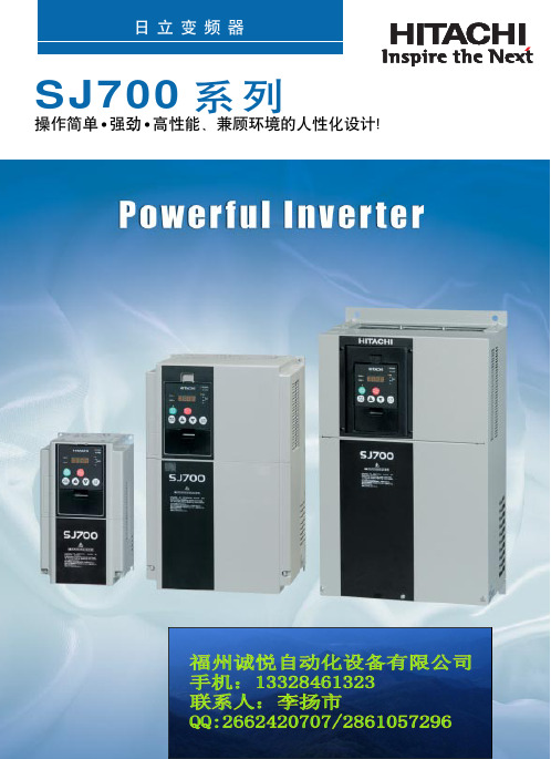
日立变频器SJ700系列彩页手册
变频器说明书大全
红邦控制技术4.ABB变频器说明书ACS400ACS500ACS5105.AB变频器说明书1336PLUS II PowerFlex 4PowerFlex 406.AC Tech变频器说明书MC1000QC SCF7.BERGES变频器说明书ACM-D2/S2/S3ACM-COMPACT8.BONFIGLIOLI邦飞利变频器说明书ACT200/400ACU200/400VCB4009.CT变频器说明书Command er GP Unidrive SP Command er SE 10.Drivecon变频器说明书XS XT XR 11.EATON伊顿变频器说明书SVX9000SPX9000MVX900012.KEB科比变频器说明书F4-S F4-F F5-M 13.LG变频器说明书iS3iH3iG514、LUST路斯特变频器说明书CDD3000CDE/CDB3000CDS400015.Moeller金钟-默勒变频器说明书DV6-340DF5116.NORD诺德变频器说明书SK300ESK400ESK5xxE17.PDRIVE变频器说明书18.PE变频器说明书SD100SD250SD45019.RICH利佳/艾瑞克变频器说明书EI-MINIEI-450EI-450M20.SEW变频器说明书MOVITRAC -31C MOVIDRIV E-60B/61B MOVITRAC -0721.SIEI西威变频器说明书ARTDriveL ARTDriveG-EV22.TMT变频器说明书PLUS VTC E 23.VACON瓦控变频器说明书NX NXS NXL 24.WEG变频器说明书CTW-04CFW-08CFW-0925.阿尔法ALPHA变频器说明书ALPHA2000G ALPHA2800ALPHA330026.艾默生(原华为)变频器说明书EV1000EV2000EV300027.爱得利变频器说明书APXG3ASASN28.爱迪生Adsen变频器说明书ADS-A29.安邦信AMBITION变频器说明书G9/P9V11G1130.安川YASKAWA变频器说明书G5G7E731.安普(AMPLE)变频器说明书AMP100032.百德福BEDFORD变频器说明书B500B80133.斑科Bantek变频器说明书BLDC34.宝德电气BODE变频器说明书BEM100BEM20035.葆德BALDOR变频器说明书10111236.贝西B&C变频器说明书BC-1000BC-2000BC-2300MX-eco/pro/multi-eco/multi-pro-1MX-eco/pro/m eco/multi-pro-237.传动之星(STAR@DRIVE)变频器说明书SD-5L-G/P/YSD-5L-S SD-7L38.创杰变频器说明书ACT-V6G/P/ZACT-M739.春日(KASUGA)变频器说明书KVFC40.丹佛斯(Danfoss)变频器说明书FC51FC100FC20041.德弗(DOVOL)变频器说明书DV300DV600ST50042.德莱尔变频器说明书DVA DVM DVS43.德力西变频器说明书CDI900044.德瑞斯(DIRISE)变频器说明书DRS1000-M DRS2000DRS280045.东达变频器说明书TDS-F8TDS-V846.东洋(TOYO)变频器说明书VF61R VF6447.东元(TECO)变频器/伺服说明书7300EV7300CV7200MA48.东芝(TOSHIBA)变频器说明书VF-nC1VF-S9VF-S1149.方禾(FangH)变频器说明书TE280F66-B F66-C50.飞兆变频器说明书FG51.佛朗克(FRANCK)变频器说明书FRS2000FRB600052.佛斯特(FIRST)变频器说明书FST-500FST-550FST-60053.富凌(FULING)变频器说明书DZB60J DZB70B DZB200M54.富士(FUJI)变频器说明书FRN-G11S FRN-P11S E1S55.高士达(GOLDSTAR)变频器GS200L56.哥伦(GRET)变频器说明书GD-V557.格立特(GREAT)变频器说明书VF10VF11VF1558.海利普变频器说明书HOLIP-A/F/H/MHOLIP-C HOLIP-P59合康亿盛高压变频器说明书HIVERT通用HIVERT矢量60.泓筌变频器说明书HC1-A HC1-M61.鸿宝(HOSSONI)变频器说明书HB-G9/P9HB280-G HB280-P62.华科(HUANIC)变频器说明书HI3G/F HI9G/F63.华蓝(HLinverter)变频器说明书HL200064.汇川(INOVANCE)(默纳克NICE)变频器说明书MD300MD300A MD32065.汇菱(HUILING)变频器说明书H300066.基创变频器说明书E35067.吉纳变频器说明书MSC-3MFI-Case00/CaseA/CaseB68.加能变频器说明书ACmaster-H7IPC-MD IPC-DR69.佳川(JiaChuan)变频器说明书BP60JCRQ70.佳灵变频器说明书JB6C-T971.金肯(JINKEN)变频器说明书JK-G/P72.九德松益变频器说明书CT-200073.开拓变频器说明书KT-A6G/P74.凯迪华能变频器说明书CD200075.康沃(博世力士乐)变频器说明书S1G2G376.科陆变频器说明书CL1700CL2700CL370077.科姆龙变频器说明书KV1900KV200078.库马克变频器说明书CMK-30079.酷马(QMA)变频器说明书Q7000Q900080.乐邦变频器说明书LB60G LB90G81.乐星产电变频器说明书Starvert82.雷诺尔变频器说明书JJR1000JJR2000JJR500083.力普变频器说明书LP10084.菱科(LINGKE)变频器说明书LK600-G/P/ZSLK80085.隆兴变频器说明书LS200A LS600LS80086.路斯特(LUST)驱动器说明书AD系列CDD系列87.伦茨(Lenze)变频器说明书8200/82108220/8240823088.麦孚变频器说明书VFD-F540VCD100089.麦格米特变频器说明书MV300MV60090.美之源(MZY)变频器说明书MZY-M/Y/Z/T/L91.蒙德(MODROL)变频器说明书IMS-GF IMS-GL2IMS-GL392.米高变频器说明书Micovert2003Micovert34 0N93.明电舍(MEIDEN)变频器说明书VT230S VT230SE VT240S94.南方安华变频器说明书A100E100S10095.能士(NSA)变频器说明书NSA20NSA8096.宁茂(赫力)变频器说明书RM597.欧陆变频器/直流调速器说明书512C590+590P98.欧姆龙(OMRON)变频器说明书3G3JV3G3EV3G3FV99.欧瑞(HFinverter)(原惠丰)变频器说明书F2000-G F3000F1000-G100.派克汉尼汾(parker)变频器说明书AC650AC650V AC690+ 101.派尼尔(Pioneer)变频器说明书VF2100VF3000VF5000 102.普传(POWTRAN)变频器说明书PI97G PI7000/7100PI7500103.群倍(QUNBEI)变频器说明书QLP5000104.日搏变频器说明书RB600RB3000RB5000 105.日锋(RiFeng)变频器说明书RF200RF9000106.日虹变频器说明书CHRH-A CHRH-C CHRH-D 107.日立(HITACHI)变频器说明书SJ100L100SJ200 108.日普(RIPOW)变频器说明书RP3200109.日拓变频器说明书HL3000110.日业(SUNYE)变频器说明书SY3200111.荣信电力电子变频器说明书HVC112.瑞恩(RELIANCE)变频器说明书PSC4000/5000/DDS5000PSC7000VZ3000113.赛普(SAPPHIRE)变频器说明书SAP500G SAP300114.赛普变频器说明书SAP900G SAP300V115.三晶变频器说明书SAJ8000116.三肯(SANKEN)变频器说明书SAMCO-i SAMCO-vm05SAMCO-e117.三菱(MITSUBISHI)变频器说明书A500E500F500 118.三木(MIKI)变频器说明书V6119.三品(SANPIN)变频器说明书SKJ SPRQ-333120.三碁(SANCH)(三川)变频器说明书SA SE121.三星(SAMSUNG)变频器说明书MOSCON-E7MOSCON-F7MOSCON-F500122.森兰(SENLAN)变频器说明书SB50SB60/61SB61Z 123.山宇变频器说明书SY6000SJR2124.珊星变频器说明书F5000F6000125.深川变频器说明书SVF2000SVF3000126.神源(SYRUNS)变频器说明书SY4000SY5000127.施耐德变频器说明书ATV38ATV58-1ATV58-2 128.时代变频器说明书TVF1000TVF3000TVF5000 129.时运捷变频器说明书SuperBona-iF/iPDB-2100130.士林变频器说明书SH系列SS系列SB系列131.世通(EACON)变频器说明书EC1000EC3000EC5000 132.收获(Seoho)变频器说明书SOHO-VD SOHO-SMS133.思达(SD)变频器说明书JPSD3000-G/P/V/H134.斯德博(STOBER)变频器说明书FAS4000FDS4000MDS5000 135.四方变频器说明书C300C320E320 136.松下(PANASONIC)变频器说明书VF0VF0C VF-8Z 137.台安(TAIAN)变频器说明书E2N2V2138.台达(DELTA)变频器说明书VFD-A VFD-B VFD-F 139.台凌(TAILING)变频器说明书TL80TL100TL100H 140.腾龙变频器说明书VG3000-G/H141.天正变频器说明书TVFS9TVFG9/P9TVFG11 142.万谷(WANGU)变频器说明书VF2000143.威尔凯变频器说明书WKF WKS WKR5000 144.威科达变频器说明书V6145.威灵(WELLING)变频器说明书WELLING-G/P/F146.微能变频器说明书WIN-VB WIN-9G WIN-9F 147.韦尔变频器说明书AC30G/P/W/H148.伟创(VEICH)变频器说明书AC20AC32AC60 149.沃森(VicRuns)变频器说明书VSI9000150.西驰变频器说明书CFC1000CFC4000151.西尔康变频器说明书H3000152.西林变频器说明书EH600A EH600M EH600W 153.西门子(SIEMENS)变频器说明书MM410MM420MM430154.现代(HYUNDAI)变频器说明书N50N100N300 155.晓磊(CHXL)变频器说明书LEI2000LEI2005LEI3000 156.信捷(XINJE)变频器说明书V5/F5157.星河(XINHE)变频器说明书SD-5L158.亚泰(YT)变频器说明书YTD-G160.阳冈电子变频器说明书G1/H1/P1E1S1 161.依尔通(Emotron)变频器说明书FDU VFX VSA 162.依托(ESTAR)变频器说明书EG/EF163.亿森变频器说明书参数表164.易能变频器说明书EDS700EDS2860165.易驱变频器说明书ED2003ED2800ED3000 166.意科(IECCO)变频器说明书SINUS-N167.英泰(Invertek DRIVES)变频器说明书OptidrivePlus 3GV OptidrivePlus3GVCompactOptidriveVTC168.英威腾(INVT)变频器说明书CHV100CHV190CHF100 169.鹰垦(INK)变频器说明书SLX170.优利康变频器说明书YD3000YD5000171.尤尼康(UNICON)(原北京兰海)变频器说明书低速大扭矩无码盘有码盘172.誉强(YUQIANG)变频器说明书YQ3000-M YQ3000-A YQ3000-G 173.远川(YCDZ)变频器说明书YC-G YC-P174.正频(JPS)变频器说明书PDS PDA/H/E175.正泰(CHINT)变频器说明书NI01176.正弦(SINEE)变频器说明书SINE300SINE303SINE307 177.正阳(Zhengyang)变频器说明书ZY29/31/98ZY-812178.中源(ZYDL)变频器说明书ZY-G800ZY-G800E ZY-A900 179.中远变频器说明书MF6MF5/20MF30 180.珠峰变频器说明书DLT-G11/P11/Z181.住友(SUMITOMO)变频器说明书HF320SF320HF430 182.紫日(CHZIRI)变频器说明书ZVF7ZVF9ZVF9V 183.南海华腾(V-T)变频器说明书V5-H E5-P V6-HACS600ACS800ACS1000PowerFlex 400PowerFlex 70PowerFlex 700SE1SW1SYN10S/T SPL200/400VF5100HG VF51RG VFDBVF61CVF61VF64VFK1/VFN 1GVX9000F5-M/S iS5iHSK530E SK700E SK750ESD700EI-500EI-550EI-600EI-700EI-7001EI-8001EI Super NMOVIRET-315/328/355/380/3150IP55 PLUS IP55 E CFW-10CFW-11EV3100EV3500TD900TD1000TD2000TD3000TD3100MSE11Z9/Z11F7J7V7PC3P5/PC514ro/multi-co/multi-pro-2FC300VLT2000VLT2800VLT2900VLT3000VLT5000 HL2000DV1000DRS30007200GA7300PA7200GSVF-A5VF-A7VF-AS1DZB300BF1S FRN-FVR-E11SMini/C1SHB280-ZMD330ME280NICE3000IPC-RF9300Vector690+590C3G3HV3G3MV3G3RVF1500-GPI7600/78PI766000SJ300SJ300-EL L200L300P VZ7000MF/MS ES/ET/EF IHF/IPF SHF/SPFS500A700E700F700D700 SB70SB100SB200BT40ATV61ATV68-1ATV68-2ATV68-3SDS4000E350E380E520H320M1X M2XVF100DV700/707SV300N310S310EV300VFD-G VFD-M VFD-S VFD-VWIN-9I WIN-9LAC61-Z AC62-LEH600ZMM4406RA706SE70J300TOPVERT TOPVERT TOPVERTVSC CDX CDU MSF ED300S ED3100Optidrive E OptidriveE1OptidriveE2OptidriveMEMA 4XSINE308SINE309 ZY-P800ZVF11VFN2TD3200TD3300。
日立SJ100系列变频器快速参考手册说明书
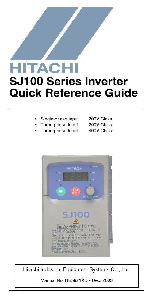
•Single-phase Input 200V Class •Three-phase Input 200V Class •Three-phase Input400V ClassManual No. NB5821XD • Dec. 2003Hitachi Industrial Equipment Systems Co., Ltd.HITACHISJ100 Series Inverter Quick Reference GuideCaution: Be sure to read the SJ100 Inverter Manual andfollow its Cautions and Warnings for the initial productinstallation. This Quick Reference Guide is intended forreference use by experienced users in servicing existinginstallations.Power Circuit Terminals–002NFE/NFU, –004NFE/NFU, –005NFEJumper+1L1L2N/L3U/T1V/T2W/T3ChassisGround–007 to 022NFE/NFU, –037LFU, 004 to 040HFE/HFUJumper+1L1L2N/L3U/T1V/T2W/T3ChassisGround–055LFU, –075LFU, 055HFE/HFU, 075HFE/HFU Jumper+1L1L2N/L3U/T1V/T2W/T3ChassisGroundControl Circuit TerminalsTerminalName Description Ratings and NotesP24+24V for logic inputs24VDC supply, 30 mA max.(Notes: Do not use for network powerDo not short to terminal L)1, 2, 3, 4, 5, 6Intelligent (program-mable) discrete logicinputs 27VDC max. (use P24 or an external supply referenced to terminal L), 4.7k Ω input impedanceL (top row)GND for logic inputs Sum of input 1 to 6 currents (Note: Do not ground)11, 12Discrete logic outputs 50 mA max. ON current,27 VDC max. OFF voltage CM2Common for logic outputs 100 mA max for sum of terminals 11 and 12 currents FMPWM output0 to 10VDC, 1 mA max., 50% duty cycle L (bottom row)Common for analog inputs Sum of OI, O, and H currents (return)OIAnalog input, current4 to 19.6 mA range, 20 mA nominalH O OI FM P24L Analog inputsAnalog outputsAlarm relayLogic outputsLogic inputsL 654321CM21211AL0AL1AL2OAnalog input, voltage0 to 9.6 VDC range, 10VDC nominal, 12VDC max., input impedance 10 k ΩH +10V analog reference 10VDC nominal, 10 mAmax.AL0Relay common contact Contact rating Max resistive load = 250V AC, 2.5A; 30VDC 3A;Max inductive load = 250V AC, 0.2A; 30VDC 0.7AMinimum load = 5VDC 100mA,100V AC 10mAAL1Relay contact, normally closed during RUN AL2Relay contact,normally open during RUNTerminal NameDescription Ratings and NotesBasic Wiring DiagramThe following wiring diagram shows the power and motor connec-tions for basic operation. The optional signal input wiring supports external Fwd and Rev Run command, and a speed potentiometer.(L1)R (L2)S (N/L3)T(T2)V(T3)W(T1)U MotorForwardLOHReverseAlarm contacts, 1 Form CRun signalFrequency arrival signal Open collector outputs:External speed reference pot.SJ100From 3-phase power input source (See specifications label on inverter for details)Logic output commonLoadLoadAnalog common Analog referenceP2421CM21211AL0AL1AL2Inputs:Inverter Keypad Operation•Run/Stop LED – ON when the inverter output is ON and the motor is developing torque, and OFF when the inverter output is OFF (Stop Mode).•Program/Monitor LED – ON when the inverter is ready for parameter editing (Program Mode). It is OFF when the parameter display is monitoring data (Monitor Mode).•Run Key Enable LED – ON when the inverter is ready to respond to the Run key, OFF when the Run key is disabled.•Run Key – Press this key to run the motor (the Run Enable LED must be ON first). Parameter F_04, Keypad Run Key Routing, determines whether the Run key generates a Run FWD or Run REV command.•Stop/Reset Key – Press this key to stop the motor when it is running (uses the programmed deceleration rate). This key will also reset an alarm which has tripped.(continued, next page...)Hz POWER ARUN PRGMINMAXHITACHIFUNC.STR1250.0Parameter Display Run/Stop LEDProgram/Monitor LEDRun Key Enable LEDRun Key Power LEDDisplay Units LEDs Hertz AmperesPotentiometer Enable LED Potentiometer Stop/Reset KeyFunction KeyUp/Down Keys Store Key•Potentiometer – Allows an operator to directly set the motor speed when the potentiometer is enabled for output frequency control.•Potentiometer Enable LED – ON when the potentiometer is enabled for value entry.•Parameter Display – A 4-digit, 7-segment display for parame-ters and function codes.•Display Units: Hertz/Amperes – One of these LEDs will be ON to indicate the units associated with the parameter display.•Power LED – ON when the power input to the inverter is ON.•Function Key – This key is used to navigate through the lists of parameters and functions for setting and monitoring parameter values.•Up/Down Keys – Use these keys alternately to move up or down the lists of parameter and functions shown in the display, and to increment/decrement values.•Store Key – When the unit is in Program Mode and the operator has edited a parameter value, press the Store key to write the new value to the EEPROM.Keypad Navigation Maph 34h 0112c 91c 0112b 92b 0112A 98A 0112121212H ––12C ––12b ––12A ––F 04F 0112d 09d 0112o.0123.4Edit12Increment/decrement valueWrite datato EEPROMDisplay dataMonitor Mode Program Mode12FUNC.STRFUNC.FUNC.12Return to parameter listFUNC.FUNC.Select ParameterEdit ParameterStore as powerup defaultpowerdownPowerup TestThe Powerup Test procedure uses minimal parameter settings to run the motor. The procedure describes two alternative methods for commanding the inverter: via the inverter keypad, or via the logic terminals.•Check power input and motor output wiring (see page4 diagram).•If using logic terminals for testing, verify correct wiring on [P24], [FW], [H], [O], and [L] (bottom row) per the diagram on page4.•Reverse [RV] input wiring (defaults to terminal [2]) is optional.Step Description Via Keypad Via LogicTerminals1Set speed command source setting A_01 = 00(keypad pot.)A_01 = 01,[H–O–L] input2Set Run FW command source A_02 = 02(Run key)A_02 = 01,[FW] input3Set Run REV command source —C_02 = 01,[RV] input4Set motor base freq.A_03 = 605Set motor poles(2 / 4 / 6 / 8)H_04 = 4 (default), change only if your motor is different6Set keypad display to monitor freq.Access D_01, press Func key, display will show 0.0Perform safety check Disconnect load from motor7Turn keypad pot.to MIN position Ensure voltage on [O]—[L] termi-nals= 0V8Run Forward command Press Run key Turn ON the[FW] terminal9Increase speed Rotate keypadpot. CW dir.Increase voltage at [O]10Decrease speed Rotate keypadpot. CCW dir.Decrease voltage at [O]11Stop motor Press Stop key Turn OFF the[FW] terminal12Run Reverse command (optional)—Turn ON the [RV]terminal13Stop motor—Turn OFF the[RV] terminalError CodesThe SJ100 series inverters will trip on over-current, over-voltage, and under-voltage to protect the inverter. The motor output turns OFF, allowing the motor to free-run to a stop. Press the Stop/Reset key to reset the inverter and clear the error.Basic Error CodesErrorCode Name Probable Cause(s)E01Over current event whileat constant speed •Inverter output was short-circuited •Motor shaft is locked•Load is too heavy•A dual-voltage motor is wired incorrectlyNote: The SJ100 will over current trip at nominally 200% of rated currentE02Over current event duringdecelerationE03Over current event duringaccelerationE04Over current event forother conditions •DC braking power(A_54) set too high•Current transformer / noise errorE05Overload protection•Motor overload is detected by theelectronic thermal functionE06Braking resistor overload•Regenerative braking resistorexceeds the usage time or usage ratio E07Over voltage protection•DC bus voltage exceeds a threshold,due to regenerative energy from motor E08EEPROM error•Built-in EEPROM memory experi-enced noise, high temperature, etc. E09Under-voltage error•DC bus voltage decreased enough tocause a control circuit faultE10CT error(current transformer)•High electrical noise near inverter •A fault occurred in the built-in CTE11E22CPU error•Built-in CPU had internal error E12External trip•[EXT] input signal detectedE13USP (Unattended StartProtection)•When (USP) was enabled, an error occurred when power was applied while a Run signal was presentE14Ground fault•A ground fault was detectedbetween the inverter output and themotor. This feature protects theinverter, and does not protect humans.Error Trip ConditionsUse function code D_08 to access the error trip conditions for the current error as shown in the table below. Use the Up and Down arrow keys to scroll through the trip condition parameters.E15Input over-voltage •Input voltage was higher than the specified value, 60 sec. after powerup E21Inverter thermal trip •Inverter internal temperature is above the thresholdE35Thermistor•Thermistor input, [THM] and [L], is over the temp. threshold---Under-voltage (brown-out) with output shutoff•Low input voltage caused theinverter to turn OFF the motor output and try to restart. If unsuccessful, a trip occurs.StepDisplay1. Access D_08d 082. Press Function KeyIf no error:_ _ _If error exists:Exx(error code)3. Press Up/Dn key (if error exists)Output frequency at trip point:10.0Motor current at trip point:0.025DC bus voltage at trip point:189.8Error CodeNameProbable Cause(s)12Restoring Factory Default SettingsActionDisplayFunction/ParameterPress ,or as needed.b --“B” Group selectedPress .b 01First “B” Group parame-terPress/holduntil...b 85Country code forinitialization selected Press . If setting iscorrect, then skip next step.0200 = Japan 01 = Europe02 = United StatesTo change country code, press or to set; to store.Press .b 85Country code forinitialization selected Press .b 84Initialization function selectedPress .000 = disable initialization, clear trip history only Press .011 = enable initialization Press .b 84Initialization now enabled to restore all defaultsPress/hold , ,and . Do not release yet.b 84First part of key sequencePress/hold (STOP)for 3 seconds, then release.d 00Final part of special sequence, “D_00” is flashingNow release the all keys together, only after “D_00” display begins blinking.EU USA JP Default parameter country code shown during initializationInitialization is complete.d 01Function code for output frequency monitor shownFUNC.12FUNC.1FUNC.12STR FUNC.2FUNC.1STR FUNC.12Note: After initializing the inverter, use the Powerup Test on page 8 to get the motor running again.Parameter Tables“D” Group: Monitoring FunctionsFunc. Code Name / DescriptionUnits D_01Output frequency monitor Hz D_02Output current monitor A D_03Rotation direction monitor—D_04Process variable (PV), PID feedback monitor %D_05Intelligent input terminal status—D_06Intelligent output terminal status—D_07Scaled output frequency monitor(output frequency x B_86 scale factor)User-defined D_08Trip event monitor —D_09Trip history monitor—DirectionForward Stop Reverse214365Terminal NumbersON OFF1211AL Terminal NumbersON OFFTrip History Navigation MapE 0760.0124.00270.01212d 0812o.0Display dataMonitor Mode12FUNC.FUNC.d 09____NoError code Output frequency at trip point Motor current at trip point DC bus voltage at trip pointFUNC.Y esNo errorError (n-1) exists?NoY esE 03E 05____No historyFUNC.Error (n-2) exists?NoY esFUNC.____FUNC.FUNC.12FUNC.No historyError exists?Parameter tables for user-settable functions follow these conven-tions:•Some parameters have 2nd motor equivalents, indicated by the x2xx parameter codes in the left-most column.•Some parameters specify an option code. Where applicable, the options codes will be in a bulleted list in the Name/Description column.•The default values apply to all models unless otherwise noted for each parameter... –FE (Europe) / – FU (U.S.) / –FR (Japan).•Some parameters cannot be edited during Run Mode, and certain Software Lock settings (B_31) can prohibit all edits. If in doubt, place the inverter in Stop Mode or consult the inverter manual for details.“F” Group: Main Profile Parameters“A” Group: Standard FunctionsFunc. Code Name / DescriptionDefaultValue Set ValueF_01Output frequency setting 0.0F_02Acceleration (1) time setting10.0F202Acceleration (1) time setting, 2nd motor 10.0F_03Deceleration (1) time setting10.0F203Deceleration (1) time setting, 2nd motor 10.0F_04Keypad Run key routing •00Forward •01Reverse00Func. Code Name / DescriptionDefault Value –FE / –FU /–FR Set ValueA_01Frequency source setting •00Keypad potentiometer •01Control terminal•02Function F_01 setting01 / 01 / 00A_02Run command source setting•01Input terminal FW or RV (assign-able)•02Run key on keypad, or digitaloperator01 / 01 / 02A_03/ A203Base frequency setting50.0 / 60.0 /60.0A_04/ A204Maximum frequency setting50.0 / 60.0 /60.0A_11O/OI–L input active range startfrequency0 A_12O/OI–L input active range end frequency0 A_13O/OI–L input active range start voltage0 A_14O/OI–L input active range end voltage100 A_15O/OI–L input start frequency enable•00Use A_11 starting value)•01Use 0 Hz01A_16External frequency filter time constant8 A_20/A220Multi-speed frequency setting0A_21 A_22 A_23 A_24 A_25 A_26 A_27 A_28 A_29.. ..A_35Multi-speed frequency settings(for both motors)0 / 0 / 50 / 0 / 100 / 0 / 150 / 0 / 200 / 0 / 300 / 0 / 400 / 0 / 500 / 0 / 600 / 0 / 00 / 0 / 0A_38Jog frequency setting 1.0 A_39Jog stop mode•00Free-run stop, jogging disabledduring motor run•01Controlled deceleration, joggingdisabled during motor run•02DC braking to stop, joggingdisabled during motor run00A_41/ A241Torque boost method selection•00Manual torque boost•01Automatic torque boost00A_42/A242Manual torque boost value11A_43/ A243Manual torque boost frequency adjust-ment10.0A_44/ A244V/f characteristic curve selection•00V/f constant torque•01V/f variable torque•02Sensorless vector control02A_45V/f gain setting100 A_51DC braking enable•00Disable•01Enable00 A_52DC braking frequency setting0.5 A_53DC braking wait time0.0 A_54DC braking force during deceleration0 A_55DC braking time for deceleration0.0 A_61Frequency upper limit setting0.0 A_62Frequency lower limit setting0.0 A_63A_65A_67Jump (center) frequency setting0.0A_64 A_66 A_68Jump (hysteresis) frequency widthsetting0.5A_71PID Enable•00PID operation OFF•01PID operation ON00A_72PID proportional gain 1.0A_73PID integral time constant 1.0A_74PID derivative time constant0.0A_75PV scale conversion 1.00A_76PV source setting•00[OI] terminal (current input)•01[O] terminal (voltage input)00A_81A VR function select•00A VR enabled•01A VR disabled•02A VR enabled except during decel02 / 00 / 02A_82A VR voltage select230/230/200400/460/400 A_92/A292Acceleration (2) time setting15.0“B” Group: Fine-tuning FunctionsA_93/A293Deceleration (2) time setting15.0A_94/A294Select method to switch to Acc2/Dec2 profile•002CH input from terminal •01transition frequency00A_95/A295Acc1 to Acc2 frequency transition point 0.0A_96/A296Dec1 to Dec2 frequency transition point 0.0A_97Acceleration curve selection •00Linear •01S-curve •02U-shape •03Reverse U-shape 00A_98Deceleration curve selection •00Linear •01S-curve •02U-shape••03ReverseU-shape00Func. Code Name / DescriptionDefault Value –FE / –FU /–FRSet ValueB_01Selection of automatic restart mode •00Alarm output after trip, automatic restart disabled •01Restart at 0Hz•02Resume operation after frequency matching•03Resume previous freq. after freq. matching, then decelerate to stop and display trip info00B_02Allowable under-voltage power failure time1.0B_03Retry wait time before motor restart1.0B_12/ B212Level of electronic thermal setting Ratedcurrent ofeach inverterB_13/ B213Electronic thermal characteristic•00Reduced torque•01Const. torque01 / 01 / 00B_21Overload restriction operation mode•00Disabled•01Enabled for accel and constantspeed•02Enabled for constant speed only01B_22Overload restriction setting Ratedcurrentx 1.25 B_23Deceleration rate at overload restriction 1.0B_31Software lock mode selection•00Low-level access, [SFT] blocksedits•01Low-level access, [SFT] blocksedits (except F_01 and Multi-speedparameters)•02No access to edits•03No access to edits except F_01 andMulti-speed parameters01B_81[FM] terminal analog meter adjustment80B_82Start frequency adjustment0.5B_83Carrier frequency setting 5.0 / 5.0 /12.0B_84Initialization mode (parameters or triphistory)•00Trip history clear•01Parameter initialization00B_85Country code for initialization•00Japan version•01Europeversion•02US version01 / 02 / 00B_86Frequency scaling conversion factor 1.0B_87STOP key enable•00Enable•01Disable00B_88Restart mode after FRS•00Restart from 0Hz•01Restart from frequency detectedfrom actual speed of motor00“C” Group: Intelligent Terminal FunctionsB_89Data select for digital operator OPE-J •01Output frequency (D_01)•02Output current (D_02)•03Motor direction (D_03)•04PID PV feedback (D_04)•05Input states for input terminals (D_05)•06Output states for output terminals (D_06)•07Scaled output frequency (D_07)01B_90Dynamic braking usage ratio 0.0B_91Stop mode selection00B_92Cooling fan control •00Fan always ON•01Fan ON during Run, OFF during Stop00Func. Code Name / DescriptionDefault Value –FE / –FU /–FRSet ValueC_01Terminal [1] function Nineteen option codes available (see page 22)00C_02Terminal [2] function 01C_03Terminal [3] function 02 / 16 / 02C_04Terminal [4] function 03 / 13 / 03C_05Terminal [5] function 18 / 09 / 09C_06Terminal [6] function 09 / 18 / 18C_11Terminal [1] active state•00Normally open [NO]•01Normally closed [NC]00C_12Terminal [2] active state00C_13Terminal [3] active state00C_14Terminal [4] active state•00Normally open [NO]01Normally closed [NC]00 / 01 / 00C_15Terminal [5] active state00C_16Terminal [6] active state00C_21Terminal [11] function Six option codes available (see page 22)01C_22Terminal [12] function 00C_24Alarm relay terminal function05C_23[FM] signal selectionThree option codes available (see page 23)00C_31Terminal [11] active state (–FU)•00Normally open (NO)•01Normally closed (NC)— / 00 / —Reserved (–FE / –FR)00 / — / 00C_32Terminal [12] active state (–FU)— / 00 / —Terminal [11] active state (–FE / –FR)00 / — / 00C_33Alarm relay terminal active state01C_41Overload level settingRated current of inverter C_42Frequency arrival setting for accel 0.0C_43Arrival frequency setting for decel 0.0C_44PID deviation level setting 3.0C_81O input span calibration Factory calibrated C_82OI input span calibrationC_91Debug mode enable •00Display •01No display 00C_92Core monitor address (reserved)0000C_93Core monitor date (reserved)—C_94Core set address (reserved)D001C_95Core set date (reserved)00Func. Code Name / DescriptionDefault Value –FE / –FU /–FR Set Value“H” Group: Motor Constants FunctionsFunc.Code Name / DescriptionDefaultValue–FE / –FU /–FRSetValueH_01Auto-tuning Setting•00Auto-tuning OFF•01Auto-tune (measure motor resis-tance and inductance, without rotating)•02Auto-tune (rotate motor)00H_02/ H202Motor data selection•00Standard motor data•01Auto-tuning data•02Adaptive tuning data00H_03/H203Motor capacity Factory setH_04/ H204Motor poles setting•2 poles•4 poles•6 poles•8 poles4H_05/H205Motor speed constant20H_06/H206Motor stabilization constant100H_20/ H220Motor constant R1InverterratingH_21/ H221Motor constant R2InverterratingH_22/ H222Motor constant L InverterratingH_23/ H223Motor constant I0InverterratingH_24/ H224Motor Constant J InverterratingH_30/ H230Auto-tuned motor constant R1InverterratingH_31/ H231Auto-tuned motor constant R2InverterratingH032/ H232Auto-tuned motor constant L InverterratingH_33/ H233Auto-tuned motor constant I0InverterratingH_34/ H234Auto-tuned motor constant J InverterratingIntelligent Input Terminal ListingSymbol Code Input Terminal NameFW00Forward Run/StopRV01Reverse Run/StopCF102Multi-speed select, Bit 0 (LSB)CF203Multi-speed select, Bit 1CF304Multi-speed select, Bit 2CF405Multi-speed select, Bit 3 (LSB)JG06JoggingDB07External DC brakingSET08Set (select) second motor data2CH092-stage accel and decelFRS11Free-run stopEXT12External tripUSP13Unattended start protectionSFT15Software lockAT16Analog input voltage/current sel.RS18Reset inverterPTC19PTC thermistor thermal protectionUP27Remote control Up func.DWN28Remote control Down func.Intelligent Output Terminal ListingSymbol Code Input Terminal NameRUN00Run signalFA101Freq. arrival type 1 – constant speedFA202Freq. arrival type 2 – over-frequencyOL03Overload advance notice signalOD04Output deviation for PID controlAL05Alarm signalAnalog Input ConfigurationThe following tables show the parameter settings required for vari-ous analog input signal types.Analog Output Function ListingThe following table shows all three functions available for assign-ment to the analog output terminal:•Terminal [FM], option set by C_23Auto-tuning ProcedureThe SJ100 auto-tuning feature calibrates the inverter to the parame-ters of a specific motor such as winding resistance and reactance. For optimum sensorless vector control, it is important to auto-tune during the initial installation, and after replacing either the motor or the inverter.Auto-tuning requires that you configure the inverter for SLV control (set A_44 = 02). Then you can perform the auto-tuning procedure, which is detailed in the SJ100 Inverter Instruction Manual.[AT]External Frequency Command InputOFF [O] — [L]ON[OI] — [L](not assigned to any inputterminal)Summation of [O] — [L] and [OI] — [L]Option Code Function Name Description Corresponding Signal Range 00Output frequency Actual motor speed, represented by PWM signal0 to max. freq. in Hz01Output currentMotor current (% of maximum rated output current), represented by PWM signal0 to 200%02Digital output frequencyOutput frequency 0 to max. freq. in Hz。
日立变频器SJ 系列彩 手册
!"#$%&'(
!"#$
!"
!" !"#$%&'()*(+,-
!"#
!"#$
!"#$%&
•
!"#$%&'
!"#$%&
!"# SJ300
!"#$%&'()*
!"#$
!"#$%&'(
!"#$ !"#
!"#SRW
SJ300
!"#$%
SJ700
!"#$%&'()
•
!"#$%&'()*
!"12
!""#$
!
!"
通用 模拟量输入
XA(0): 0~10V(O端子) XA(1): 4~20mA(OI端子) XA(2): 0~10V(O2端子)
通用输出端子 最大6点<Y(00)~Y(05)>
通用 模拟量输出
YA(0):可分配到FM端子 YA(1):可分配到AM端子 YA(2):可分配到AMI端子
程序控制命令(循环、无条件分支、条件分支、时间控制、子程序、其他)
(SJ700-
)
007HFEF2 015HFEF2 022HFEF2 040HFEF2 055HFEF2 075HFEF2 110HFEF2 150HFEF2 185HFEF2 220HFEF2 300HFEF2 370HFEF2 450HFEF2 550HFEF2
007HFUF2 015HFUF2 022HFUF2 037HFUF2 055HFUF2 075HFUF2 110HFUF2 150HFUF2 185HFUF2 220HFUF2 300HFUF2 370HFUF2 450HFUF2 550HFUF2
日立 SJ100系列 变频器 说明书
输入
%值
A14
10V 20mA
A11
A15=01
0 Hz
0V 4mA
A13
输入
A14
10V 20mA
%值
DOP,DRW,DOP+ EU/ US
3-12
A US
DOP,DRW,DOP+ EU/
A
DOP,DRW,DOP+
EU/
US
V/F
3-13
V 100%
A42=11
11.8%
A
0 6.0Hz 30.0Hz A43=10%
PRG
POWER Hz A
RUN
STOP RESET
MIN
MAX
/
2-26
10 10. 10
/
/
STOP RESET
RUN
FUNC
3
3-2
3-3
HITACHI
RUN
PRG
POWER Hz A
RUN
STOP RESET
MIN
MAX
FUNC 1
2 STR
/ LED / LED
LED /
LED /
B90
3-25
3-26
B
DOP,DRW,DOP+ EU/ US
B US
3-27
DOP,DRW,DOP+ EU/
3-28
C
C
DOP,DRW,DOP+
EU/
US
3-29
C
DOP,DRW,DOP+
EU/
US
3-30
3-31
3-32
B
DOP,DRW,DOP+ EU/ US
系列变频器用户手册
DHVECTOL-DI高压大功率变频调速装置用户手册东方日立(成都)电控设备有限公司目录前言3安全注意事项3第一章产品简介51.开箱检查注意事项52.变频器型号说明53.变频器组件64.标准配置75.产品使用环境86.使用注意事项8第二章产品技术概要91.产品特点92.产品系列技术参数(见下面表格) 可以根据客户要求定做13第三章原理与功能说明151.结构原理152.功能说明20第四章变频器接口241.变频器基本接口242.变频器基本接口信号表25第五章变频器操作261、变频器变频控制方式选择262、控制柜低压送/掉电操作(送低压380V/50Hz控制电源)263、变频器就地控制26第六章参数说明271.变频器系统及电动机驱动相关功能272.设定变频器工作级数28第七章电动机和变频器电气参数计算相关功能371.电压检测372.电流检测373.开关量输入相关功能384.开关量输出相关功能415.模拟量输入相关功能426.模拟量输出相关功能447.通讯相关功能468.瞬停和工变互切功能46第八章安装与维护481.安装环境482.高压部分安装483.大电流部位的安装494.信号线路的安装505.安装安全规范及其注意事项506.维护说明50第九章故障诊断511.故障分类及排除措施512.变频器本体故障52第十章其它531.厂家三包532.用户定货须知53附录:296主控系统功能表54前言感谢贵公司选用东方日立(成都)电控设备有限公司的无电网污染高压大功率变频器产品,成为我公司尊贵的用户!无电网污染高压大功率变频器是当代先进的电气传动技术与电力电子应用技术结晶的产物。
东方日立(成都)电控设备有限公司采用的是完全适合于中国电网以及电动机的先进高压变频原理及先进的工艺制造技术,东方日立运用这些技术生产出可靠性高、性能良好的系列化变频器产品,为各行各业的用户提供最优良的调速手段,我们致力于与我们的用户一起为我国的节能事业努力奋斗。
日立工业设备系统有限公司变频器MODBUS RTU驱动程序说明书
接方式。
) 3 通讯设置 本节给出连接人机界面和外接控制器的设
"3 通讯设置 " ( 第 8 页 )
置示例。
4 设置项目
本节介绍人机界面上的通讯设置项目。
)"4 设置项目 " ( 第 20 页 )
请在 GP-Pro EX中或在离线模式下进行人
机界面的通讯设置。
5 电缆接线图
本节介绍用于连接人机界面和外接控制器
PS-3711A PS4000*3
PL3000
COM1*1*2, COM2
COM1*1, COM2*1, COM3*2 , COM4 COM1*1, COM2*2
COM1, COM2 COM1*1*2, COM2*1, COM3, COM4
PE-4000B Atom N270 COM1, COM2
PE-4000B Atom N2600 COM1, COM2
(2 线 )
( 第 10 页 )
" 电缆接线图 2" ( 第 37 页 )
SJ700-2
SJ700-FF2
变频器上的 RS-485 接口
RS-422/485 " 设置示例 3"
(2 线 )
( 第 12 页 )
" 电缆接线图 2" ( 第 37 页 )
SJ200 SJ200-F 变频器上的串口
2
选择外接控制器 ................................................................................................................ 7
3
通讯设置........................................................................................................................... 8
SDRIVE700 系列变频器 说明书
修订本
日期 01 / 03 / 2006 16 / 03 / 2007 修订 A B 说明 最新软件版本 SW Ver 1.02 更新图表和漏印。新规格。规格更新。 软件版本 1.3 的软件更新(2)
3
SDRIVE 700
POWER ELECTRONICS
目录
安全规范 ...................................................................................................................................... 1. 绪论 ...................................................................................................................................... 1.1. 指定型号..................................................................................................................... 1.2. 产品详述..................................................................................................................... 安装和连接................................................................................................................
东方日立高压变频用户使用手册
东方日立(成都)电控设备有限公司高压大功率变频器HI系列用户使用说明书( Ver.A )目录1.简述 (3)2.变频装置和外部的接口信号列表 (4)3.变频操作 (7)3.1 互锁 (7)3.2 电机速度控制 (7)3.3 启/停变频器的操作流程 (8)4.显示界面 (11)4.1 条形图 (11)4.2 故障显示 (13)4.3 互锁纪录显示 (17)4.4 DIO(输入和输出接触点显示)界面 (18)附:常见故障及处理 (19)1、简述日本日立公司生产的High V oltage Inverter产品是一种交流电机的速度调节控制装置。
变频器的控制方式采用多级PWM叠加技术,结构采用多个变频器单元串联叠加输出的方式。
日立公司的6KV(10KV)系列变频器每相5(8)级单元,变频器输出电压由所有单元输出叠加而成,波形非常接近于正弦波,谐波含量很低,极大的减小了对交流电机的谐波污染。
整套变频装置由旁通柜,变压器柜,功率单元柜和控制柜四部分组成。
在旁通柜内,装有高压断路器和隔离刀闸等,可实现变频和工频的切换,当变频器在运行中发生重故障时,变频器发出变频切换到工频的指令,也可根据需要,人为的切换到工频。
在变压器柜内,装有多重移相变压器,原边绕组采用星形接法,副边绕组采用延边三角形接法和星形接法,可有效的抵消电网中的偶次谐波,并可有效的滤除某些奇次谐波,尽量减少变频器电源的谐波污染,变压器能承受系统过电压和变频装置产生的共模电压以及谐波的影响。
在功率单元柜内装有功率单元,变频器的输出电压为每个单元输出的PWM波形叠加后的输出。
在控制柜内,装有控制各个回路启停的开关和控制各个功率单元协调工作的控制板,以及整套变频装置同外部系统的接口等。
对变频器的启停操作,通过切换开关,既可以通过就地的按钮控制,又可通过远方的DCS控制来完成。
变频装置根据DCS给出的速度调节信号自动的控制电机的转速,并且在就地和远方都可以监视变频装置的状态。