GE E-CELL模块用户手册
E-Cell-3X 用户手册

6.5 排水和通风
排水的设计应能排掉每个E-Cell-3X模块所生产的28gpm (6.4m3/hr)产水流量,0.40pgm (90L/hr)极水 排出流量以及2.8pgm (0.64m3/hr)浓水排放流量。
极水流应有通风口,因为它含有少量氢气、氧气,还可能含有氯气(如果极水流里有氯离子的话)。 (氢气和氧气会以2:1比例混合,混合气体产生的最大速率约为11.4毫升/安培/分钟)
(氢气,干燥气体所处温度25℃,1.0atm)。确保通风能使氢气含量保持在4%之下。
各排水系统的设计应能保证E-Cell-3X模块处于待机模式时不排水。
9
7. 启动
7.1 概述
系统启动涉及到下述基本步骤: 1. 系统充满反渗透水,或更优质的水。 2. 设定淡水流量。 3. 设定浓水排放流量。 4. 设定极水流量。 5. 调整淡水流量和压力。 6. 调整浓水流量和压力。 7. 调整极水流量。 8. 细调淡水流量、浓水流量和极水流量以及压力至最佳值。 9. 启动整流器。
极水流
淡水中的一小部分流经E-Cell系统中每个E-Cell-3X模块极水室,并且在离开系统后 直接排放的水。
淡水产水
由E-Cell系统生产的去离子水。
整流器
直流电源。
1
2. 个人安全防护措施
E-Cell-3X模块可找到下述图标,本手册中也包含这些图标。
图标
功能 警告!
说明
任何时候不应由未经培训的人员操作 E-Cell-3X 模块。除非你已了 解本手册的内容并已接受培训,否则不要尝试操作 E-Cell-3X 模块。 如果不遵守本手册中的步骤,可能会导致严重伤害。
17
9 操作说明
18
9.1 流量
MK-3使用手册

4.1 E-Cell 模块最大功率要求................................................................................ 4-7 4.2 工作电流......................................................................................................... 4-7 4.3 E-CELL 模块电气设计 .................................................................................... 4-8
8. 关闭程序.............................................................................................................. 8-15
8.1 E-CELL 模块在自动操作模式下关闭............................................................. 8-15 8.2 E-CELL 模块 延长关闭 ................................................................................. 8-15
E-CELL操作说明书

操作手册FOR THE120 GPM, 27.3 m3/hE-CELL SYSTEM TM注意:本手册含有对 E-Cell 公司所提供的水处理系统的操作和维护指导。
在操作和维修该系统时,必须始终遵守手册中的程序。
此中文文本的内容与英语版本的用户手册有分歧时,以英文版本为准。
1. 人身安全注意事项E-CELL MK-2 STACK™1.1 电气1. 定期检查接线端子是否接触良好。
2. 如发现有损坏的电气元件,在修复或更换前要先隔离该元件。
3. 检查电器箱密封良好以防进水。
4. 只允许有资格的电气技术人员进行检修工作。
5. 整流器处于工作状态时不可切断E-Cell MK-2模块上的电源线。
1.2 机械E-Cell MK-2 模块含有电器元件,可能造成触电危险,故请勿将工具、螺丝等放置在E-Cell 模块上。
除专业人员外,不要调整E-Cell MK-2 模块上的螺丝。
模块端板间的距离在出厂前已经精确调节,过度调整可能造成永久损害。
1.2.1 泄漏MK-2 模块的最大操作压力是 100 psi (6.8 bar) ,在正常压力下模块不应泄漏。
如发现模块漏水,应停机检查泄漏位置和模块端板间距。
若漏水无法解决,请立即联系E-Cell 公司。
1.2.2 离心泵1. 严禁在运转的离心泵上工作。
如需维护必须停机并在泵上加标识。
2. 确保水泵电机风扇的通风畅通。
1.2.3 水力E-Cell™ 系统通过不同管径的管道输送大量的水,如非正常的操作可能引起设备损坏、高压水泄漏以致人身伤害。
1. 确认所有的管道都有足够的固定和支撑。
2. 在开启系统进水阀门前,保证出口阀门已经开启。
1.3 停机必须遵守停机程序来保证工作人员的安全。
不仅需注意转动设备和电器,对容器或水管也应小心。
1.4 通道在 E-Cell™ 设备周围应有足够的通道和照明以便操作和维护的安全。
1.5 安全用具当可能暴露在酸碱环境中时,须穿戴橡胶手套、橡胶服、面罩和防护眼镜。
GE Grid Solutions 8系列高级馈线控制器产品手册说明书

GEGrid Solutionsimagination at workInnovative Technology& Design• Advanced feeder One Box Solution for protection, control monitoring anddiagnostics of single/dual feeder applications Feeder and Bay Controller Solutions for Industrial and Utility ApplicationsThe Multilin™ 850 relay is a member of the Multilin 8 Series protective relay platform and has been designed for the management, protection and control of feeder applications. The Multilin 850 is used to provide primary (main) or backup protection for underground and overhead single or dual feeders for utility and industrial power networks.With 11 Switchgear control elements, fully configurable Single Line Diagram on a large color graphical display, 36 alarm integrated annunciator panel and 20 push buttons makes the 850 the ideal choice for bay control and protection as a “One Box Solution”.Designed with advanced communications options and detailed asset monitoring capabilities, the Multilin 850 provides advanced functionality, including high-performance protection, extensive programmable logic and flexible configuration capabilities. With support for industry leading communications protocols and technologies, the 850 provides easy integration into new or existing SCADA or DCS for enhanced situational awareness.Key Benefits• One Box Solution with advanced logic and configuration flexibility, providing primary or backup protection for up to 2 feeders or feeders with 2 sets of voltage inputs • User configurable Single Line Diagram on color display for local control, system status, and metering • Advanced breaker diagnostics with comprehensive fault and disturbance recording• Integrated arc flash detection using light sensors supervised by overcurrent to reduce incident energy and equipment damage • Advanced cyber security features including AAA, Radius, RBAC, and Syslog enabling NERC ® CIP requirements • Draw-out design simplifies testing, commissioning and maintenance, increasing process uptime • Patented environmental monitoring, providing visibility to changes in environmental conditions that can affect relay lifeApplications• Single/dual feeder applications for utility, oil & gas, mining & metals, process industry, commercial, and waste water segments • Fast protection pass enabling load shedding schemes • Reliable automatic bus transfer & autoreclose schemes • Bay controller for wide range of switchgear applications • High speed fault detection for arc flash mitigationMultilin 850WARRANTYYEAR850Multilin 850 OverviewThe Multilin 850 is an advanced feeder protection device designed for high performance, protection, control and monitoring of incoming and outgoing feeders.With up to 57 digital inputs and 22 digital outputs in a compact box, the 850 provides a versatile and cost effective control, protection, measurement & monitoring solution. Flexelements and Flexlogic enable users to customize schemes to meet a variety of applications.From dual main to main-standby configurations, the Multilin 850D delivers a more economical and reliable solution, enabling customers to reduce hardware requirements and simplify device integration, including safe and secure Wi-Fi communications for system configuration and diagnostics. Bay Controller/One Box SolutionThe 850 offers comprehensive switchgear control aided by a configurable Single Line Diagram & breaker control. A total of 10 switchgear elements can be displayed and 8 elements controlled. The integrated solution for protection, control, monitoring and diagnostics eliminates the need for other external devices thus offering an integrated solution for switchgear systems. The device supports 6 user programmable pages. The Multilin 850 is an integrated solution that performs protection, control & monitoring of assets, and ease of retrieval of fault & event records. Coordinating remotely with SCADA over multiple communication protocols gives the Multilin 850 an added advantage for fast and efficient management of fault isolation and service restoration.The Multilin 850 is a cost-effective retrofit solutions where individual components of protection, metering, control switches, annunciator & panel mimic can be replaced by only one relay. Switchgear Control and Configurable SLDThe Multilin 850 provides a configurable dynamic SLD up to six (6) pages for comprehensive switchgear control of up to 2 breakers and 9 disconnect switches; including interlocks. Up to 15 digital and metering status elements can be configured per SLD page. These can be configured to show breakers, switches, metering, and status items.Individual SLD pages can be selected for the default home screen pages. Automatic cycling through these pages can also be achieved through default screen settings.The provision of such powerful control and display capability within the relay (“One Box” concept) eliminates the need for external controls, switches and annunciation on the panel reducing equipment and engineering cost. Annunciator Panel and Virtual Push ButtonsThe Multilin 850 offers a configurable annunciator panel that can be constructed to show up to 36 alarms in either self-reset mode or latched mode per ISA 18.1 standard similar to a physical annunciator panel; eliminating the need for a physical one. This removes the need for additional programmable LEDs. The alarms can be displayed on the front panel in a configurable grid layout of 2x2 or 3x3.The Multilin 850 extends the local control functionalities with 20 virtual pushbuttons that can be assigned for various functions. Each programmable pushbutton has its own programmable LED which can be used to acknowledge the action taken by the tab pushbutton.With a fast protection pass, running every 2 msec, the 850 relay provides fast response to current, voltage, power, and frequency protection elements; helping reduce stress on assets. The Multilin 850 supports the latest communication protocols, including DNP, ModBus, IEC 60870-5-103, IEC 62439/PRP and IEC 61850; facilitating easy integration into new or existing SCADA/DCS networks.Functional Block Diagram850 Distribution FeederWith support for up to 8 CT inputs & 2 sets of 4 traditional VT inputs, the 850 can be used for 2 feeders or feeders with 2 sets of voltage inputs, simplifying system architectures and operational costs.The 850 offers redundancy with the same number of devices, enabling:Architecture Simplification - Reduced Number of Devices• Less capital cost • Less O&M costMean Time to Repair - Less than 15 minutes• Field swappable PSU • Draw out construction• Ready to consume service reportsExtended Asset and Relay Life• Built-in Environmental monitoring • Advanced breaker monitoring• TGFD and Cable incipient fault detection/locationSimplified Management - Platform Based Solution• Reduced training needs• Standardized part number across systems • Harmonized look and feel, operational experienceProtection & ControlAs part of the 8 Series family, the Multilin 850 provides superior protection and control. The 850 offers comprehensive protection and control solutions for incoming, outgoing bus-tie/bus-coupler feeders. It contains a full range of selectively enabled, self-contained protection and control elements.The voltage and frequency protection functions detect abnormal system conditions, potentially hazardous to the system. Some of these conditions may consist of over and undervoltage, over and underfrequency, and phase reversal.Fast UnderfrequencyThe 850 has an 8 stage Fast Underfrequency element that measures frequency by detecting the consecutive voltage zero crossings and measuring the time between them. The measured frequency has a range between 20 to 70 Hz. This is useful for performing fast load-shedding when frequency variations from unbalance conditions arise due to:• Inadequate load forecast or deficient generation capacity programming.• Busbars, generator group or interconnection feeders trip.• System splits into islands.FlexCurves™For applications that require greater flexibility, FlexCurves can be used to define custom curve shapes. These curves can be used to coordinate with other feeders to achieve fault selectivity.RTD ProtectionThe Multilin 850 supports up to 13 programmable RTD inputs that can be configured for an Alarm or Trip.The RTDs can be assigned to a group for monitoring ambient temperatures or any other desired temperature. The RTD voting option gives additional reliability to ignore and alarm for any RTD failures.Integrated Arc Flash ProtectionThe Multilin 8 Series supports an integrated arc flash module providing constant monitoring for an arc flash condition within the switchgear, motor control centers, or panelboards. With a 2ms protection pass, the 8 Series is able to detect light and overcurrent using 4 arc sensors connected to the relay. In situations where an arc flash/fault does occur, the relay is able to quickly identify the fault and issue a trip command to the associated breaker thereby reducing the total incident energy and minimizing resulting equipment damage.Self-monitoring and diagnostics of the sensors ensures the health of the sensors as well as the full length fiber cables. LEDs on the front panel display of the 850 can be configured to indicate the health of the sensorsand its connections to the relay.Dual feederRedundant feeder850WANT TO LEARN MORE?EXPLORE IN 3DMV SwitchgearMultilin 8 SeriesFast, reliable arc flash protection with integrated light based arc flash sensors. This delivers detection in as fast as 2 msec, reducing the costs associated with equipment damage and unplanned downtime.Inputs and OutputsThe 850 provides a max of 57 Digital inputs and 22 Digital outputs with an option for 7 Analog Outputs (dc mA), 4 Analog Inputs (dc mA), and 1 RTD input. The configurable analog inputs can be used to measure quantities fed to the relay from standard transducers. Each input can be individually set to measure 4-20 mA, 0-20 mA or 0-1 mA transducer signals.Advanced AutomationThe Multilin 850 incorporates advanced automation capabilities which exceed those found in most feeder protection relays. This reduces the need for additional programmable controllers or discrete control relays including programmable logic, communication, and SCADA devices. Advanced automation also enables seamless integration of the 850 into other protection or process systems (SCADA or DCS).FlexElements™FlexElement is a universal comparator, that can be used to monitor any (analog) actual value measured or calculated by the relay, or a net difference of any two analog (actual) values of the same type.The element can be programmed to respond either to a signal level or to a rate-of-change (delta) over a pre-defined period of time.This can be used to generate special protection or monitoring functions which allow the user to flag a user-defined abnormality to give better visibility to a certain condition.FlexLogic™FlexLogic is the powerful programming logic engine that provides the ability to create customized protection and control schemes, minimizing the need for and associated costs of auxiliary components and wiring. Using FlexLogic, the 850 can be programmed to provide the required tripping logic along with custom scheme logic for feeder control interlocking schemes with adjacent protection (for example, preventing sympathetic tripping of healthy feeders), and dynamic setting group changes.Breaker Health MonitoringThe breaker is monitored by the relay not only for detection of breaker failure, but also for the overall “breaker health” which includes:• Breaker close and breaker open times • Trip circuit monitoring • Spring charging time • Per-phase arcing current • Trip countersAll algorithms provide the user with the flexibility to set up initial breaker trip counter conditions and define the criteria for breaker wear throughouta number of set points.Breaker Health Reporting assists Condition-Based Maintenance and savings in Operational CostsMonitoring & DiagnosticsThe Multilin 850 includes high accuracy metering and recording for all AC signals. Voltage, current, and power metering are built into the relay as a standard feature. Current and voltage parameters are available as total RMS magnitude, and as fundamental frequency magnitude and angle.Environmental MonitoringThe 850 has an Environmental Awareness Module (EAM) to record environmental data over the life of the product. The patented module measures temperature, humidity, surge pulses and accumulates the events every hour in pre-determined threshold buckets over a period of 15 years. This data can be retrieved using the EnerVista Setup Software. This report helps identify the operating condition of the installed fleet so that remedial action can be taken.850Environmental health report is available via Multilin PC SoftwareMeteringThe Multilin 850 offers high accuracy power quality monitoring for fault and system disturbance analysis. It delivers unmatched power system analytics through the following advanced features and monitoring and recording tools:• Harmonics measurement up to 25th harmonic for both currents and voltages including THD.• The length of the transient recorder record ranges from 31 to 1549 cycles (typically half a second to half a minute).• 32 digital points and 16 analog values.• Comprehensive data logger provides the recording of 16 analog values.• Detailed Fault Report. The 850 stores fault reports for the last 16 events. 1024 Event Recorder.CommunicationsThe Multilin 8 Series provides advanced communications technologies for remote data and engineering access, making it easy and flexible to use and integrate into new and existing infrastructures. Direct support for fiber optic Ethernet provides high-bandwidth communications, allowing for low-latency controls and high-speed file transfers of relay fault and event record information. The 850 also supports two independent IP addresses, providing high flexibility for the most challenging of communication networks. Providing several Ethernet and serial port options and supporting a wide range of industry standard protocols, the 8 Series enables easy, direct integration into DCS and SCADA systems. The 8 Series supports the following protocols:• IEC 61850 (8 Clients, 4 Logical Devices, Tx & Rx expansion, Analog GOOSE), IEC 62439 / PRP• DNP 3.0 serial, DNP 3.0 TCP/IP, IEC 60870-5-103, IEC 60870-5-104• Modbus RTU, Modbus TCP/IPThe 850 has two interfaces, a USB front port and Wi-Fi for ease of access to the relay.Wi-Fi Connectivity:• Simplify set-up and configuration• Simplify diagnostic retrieval• Allows personnel to be a safer distance from the front of the switchgear • WPA-2 securityCyber SecurityThe 8 Series delivers a host of cyber security features that help operators to comply with NERC CIP guidelines and regulations.• AAA Server Support (Radius/LDAP)• Role Based Access Control (RBAC)• Event Recorder (Syslog for SEM)Role, User, PasswordEncrypted (SSH)Security ServerCyber Security with Radius AuthenticationPLC / Gateway850869845MM200MM300ControllersReason S20Ethernet SwitchLV Network850 Menu path display indicating location within menu structureSoft menu navigation keysLED status indicatorsGraphic ControlPanel (GCP)Navigation keysFront USB portCaptive screw prevents inadvertent or unauthorized draw-outContext-sensitive menu for fast navigation Front View - Advanced Membrane Front PanelDimensions & MountingStandard serial and RJ45 Ethernet moduleAdvanced communica-tions module (Fiber Optic or Copper ports)CT, VT inputsGrounding screwPower supplyRTDsDigital I/O, DCmA, Arc Flash sensorsRear ViewEXPLORE IN 3D8.42”9.90”1.55”7.55”Optional IP20 cover available10 User-ProgrammablePush Buttons850 850D Wiring DiagramACCESS POINT850 850E Wiring DiagramPHASE CTsDIRECTION OF POWER FLOW FOR POSITIVE WATTS POSITIVE DIRECTION OF LAGGING VARSD9C O MN NINSTRUCTION MANUALSEE VT WIRING INCONNECTIONWYE VT INSTRUCTION MANUALINPUT WIRING INSEE GROUND 52b52a850-E Industrial Feeder Protection SystemJ9 J10 J11 J12 J13 J14OPEN DELTA VT CONNECTIONN N A I G I sg I C I N B I CANRESRVD 10D8D D745CV B V A V XV X V C V B V A V COMPUTERPERSONAL COMMUNICATIONSD1D2D3D D D6S L O T ASLOTS J & KDA O L CIRCUITCLOSECIRCUITTRIP POWERCONTROL RS485COMMUNICATIONS IRIG-B SLOT F: I/O_AVOLTAGE INPUTSCURRENT INPUTSETHERNETCOMPUTERPERSONAL USBPWR SUPPLY STUDGND BUSGROUND BUS MANUALIN INSTRUCTION MONITORING CLOSE COIL SEE TRIP AND CONTROL POWERSHOWN WITH NO OUTPUT CONTACTS 52F2F1O U T P U T R E L A Y SD I G I T A L I N P U T SVVF24F23F22F12F11F10F9F8F7F6F5F4J16F3RELAYFAILURE CRITICAL AUXILIARY 3CLOSETRIPDN U O R G LA R T U E N EN I L A1A2A3J14J13J12J11J10J9J1 J2 J3 J4 J5 J6 J7 J8 K7 K8G/H2G/H1O U T P U T R E L A Y SG/H24G/H23G/H22G/H12G/H11G/H10G/H9G/H8G/H7G/H6G/H5G/H4G/H3SLOT G OR H: I/O_A* (OPTIONAL)ACCESS POINTJ15AUX VTAUXILIARY 4AUXILIARY 9AUXILIARY 10AUXILIARY 11AUXILIARY 12AUXILIARY 16DCmA I/OANALOG OUTPUTANALOG INPUTRTD12345671234ANY MEASURED OR METEREDANALOG PARAMETER OUTPUTSAMBIENTTEMPERATURE+++++++++++SLOT G: I/O_L (OPTIONAL)A R C F L A S HSLOT H: I/O_F (OPTIONAL)SLOT B OR C: I/O_R OR I/O_S* (OPTIONAL)* SUPPORTS 10 OHM COPPER RTD AS WELL* SLOT H I/O_A IS AVAILABLE WHEN SLOT G IS WITH I/O_LANY MEASURED ORMETERED ANALOG PARAMETER INPUTSCABLE SHIELD TO BE GROUNDED AT PLC/COMPUTER END ONLYRTD RTDFront PanelSLOT D**SLOT ERear PanelC O M850OrderingCONFIGURE ONLINE850* **NN *****A ************N DescriptionAAdvanced - CyberSentry Level 1Note: Harsh Environment Coating is provided as standard on all 8 series units.* HV I/O, Option A - Max 2 across slots F through HArc Flash Detection (Option F): Includes 4 x Arc Flash sensors, each 18 feet (5.5 meters) longIEC is a registered trademark of Commission Electrotechnique Internationale. IEEE is a registeredtrademark of the Institute of Electrical Electronics Engineers, Inc. Modbus is a registered trademark ofSchneider Automation. NERC is a registered trademark of North American Electric Reliability Council. NISTis a registered trademark of the National Institute of Standards and Technology.GE, the GE monogram, Multilin, FlexLogic, EnerVista and CyberSentry are trademarks of General ElectricCompany.GE reserves the right to make changes to specifications of products described at any time without notice andwithout obligation to notify any person of such changes.imagination at work GEA-32050(E)Copyright 2018, General Electric Company. All Rights Reserved.。
GE海洋应用电力组件说明书

COMPACT and SAFERReliable top PERFORMANCEWORLDWIDE presenceELECTRICAL POWER COMPONENTS FOR YOUR MARINE APPLICATION COM PACT AND SAFER / RELIABLE TOP PERFORM ANCE / WORLDWIDE PRESENCEToday 90% of the world’s goods are transported over water. From the most advancedfrigates to the largest luxury cruise-liners and drilling rigs, we power, propel and position the marine industry.The available space on your boat is very precious. At GE we have developed and certifi ed a full range of modular devices, industrial breakers and control products that provide you excellent electrical protection while saving space on board .The environmental conditions on your ship can be very demanding with extremely hard levels of temperature and humidity, as well as strong vibrations. Through our extensive research and experience you benefi t from highly reliable power components with top performance , even under very demanding conditions .With our worldwide presence in over 140 nations you can be sure of a wide availability of complete systems and spare parts, anywhere in the world. This enables you to greatly reduce your ship’s maintenance time .ELECTRICAL POWER COMPONENTSfor your marine applicationThe space on your boat is very precious. Every area is designed to host people and goods in an optimized way. The available space for electrical power and services therefore needs to be optimized as much as possible.At the same time the electrical demands on your ship become greater and greater (e.g. communication and energy effi ciency systems), increasing the need of electrical power and services.At GE we have developed and certifi ed a full range of compact modular devices, industrial breakers and control products with a strong focus on size reduction, providing you excellent protection while you save space on board .Unibis, for example, allows you to save up to 50% on space indistribution boards.Compact and safer“ O ur range of breakers and auxiliaries provide you excellent protection in compact frames, allowing you to save space on board ina secure way.”The environmental conditions on your ship can be verydemanding. Electric devices and protections are often located in small spaces, where they reach extremely hard levels of temperature and humidity. Those conditions can change a lot depending on climate and working conditions.Moreover, vibrations caused by navigation waves and running engines are mechanically demanding for all components of your ship.Therefore the electric distribution in your ship requires devices and systems with a specifi c electrical and mechanical performance. Through our extensive research and experience you benefi t from highly reliable power components with top performance, also under very demanding conditions.With our Entelliguard G breaker, for example, we guarantee you a 2.500 A nominal current without derating up to 70°C.!While cruising for thousands of kilometers around the globe, your ship can be far away from its construction site, with very little time to stop for maintenance and very little time to wait for spare parts. With our worldwide presence in over 140 nations you can be sure of a wide availability of complete systems and spare parts, anywhere in the world. We offer a range of products with international certifi cation by all main IACS Certifi cation Societies to cover your requests all around the world.Effi cor, for example, is a global platform for contractors and thermal overload relays that has conformity to the relevant international standards.Reliable top performanceWorldwide presenceur extensive researchof complete systems andDiscover our product rangeEntelliGuard*GUnibis DPCModular components People and line protectionIndustrial breakers Main power protectionControls & PEL Power command and controlsA complete range for people and line protection with Miniature Circuit Breakers, Residual Current Devices and auxiliaries, up to 4 poles and 125 A.Including Unibis* compact range.Moulded Case Circuit Breakers, up to 1.600 A and 690Vac, and Air Circuit Breakers, up to 6.400 A and 1.000Vac.Including Entelliguard G* global ACBs line.A complete offer of Contactors, Thermal Overload Relays, Manual Motor Starters, Auxiliaries and Soft Starters.Including Efficor* contactor line with best performances.Series EP-MCBs Series EPC-MCBs Diff-o-Click RCDs CA-CBRecord PlusEffi cor relaysSurion Manual motorstartersPush-buttons Series P9Compact Soft StartersEffi corCertifi cationsOur products are certifi ed by most Classifi cation Societies that are members of The International Association of Classifi cation Societies (IACS). We can therefore guarantee you top quality and international recognition of our entire product range.Easy online availability of full range in distribution,protection and control productsGE Industrial Solutions has integratedmore than 13.000 references in the EPLAN data portal. Each product reference contains technical data, macro schemes and high quality 2D & 3D images to easily work on electrical design projects.This upload allows you to work in EPLAN Electric P8, EPLAN Pro Panel or EPLAN Engineering Center using the complete GE Industrial Solutions product basket.WorldwideIEC Solution inGE Industrial Solutions116609 GE Industrial Solutions is a fi rst class global supplier of low and mediumvoltage products including wiring devices, residential and industrialelectrical distribution components, automation products, enclosuresand switchboards. Demand for the company’s products comes fromwholesalers, installers, panelboard builders, contractors, OEMs andutilities worldwide.694550Ref. G/1420/E/EX 1.0 Ed. 09/15 /markets/marine© Copyright GE Industrial Solutions 2015。
GE PLC扩展模块说明书IC697ALG230
2
7DE0:9FC7%
Analog Input System, High Level, 16 Channels
Functions
WH$%\MAH%6$)$/%5("/'A%1(=.+%#.K#L#+$J%N'*%+H$% U*'A*"JJ"K/$%6'AMG%&'(+*'//$*%]U6&^%"GG$=+#% "("/'A%M(=.+#%'N%.=%+'%B:%)'/+#%N.//%#G"/$I%'*%>%+'%8:% JM//M"J=%G.**$(+%/''=%#MA("/#V%WH$#$%M(=.+#%"*$% G'()$*+$-%+'%-MAM+"/%N'*J%N'*%.#$%KL%+H$%&U_%'*%'+H$*% G'(+*'//$*#%"GG$##M(A%"("/'A%M(=.+#%)M"%+H$%@,;% K"GX=/"($V% &'()$*+$-%-"+"%M#%=*$#$(+$-%"#%8`#%G'J=/$J$(+% ]#MA(%a%BC%KM+#^V%WH$%K"#MG%G'()$*+$*%M#%B>%KM+#% *$#'/.+M'(%]B%="*+%M(%B29F>^P%"(%')$*#"J=/M(A%"(-% ")$*"AM(A%+$GH(Mb.$%N.*+H$*%$(H"(G$#%+HM#% *$#'/.+M'(V%1(=.+#%"*$%=*'+$G+$-%"A"M(#+%+*"(#M$(+%"(-% #+$"-L0#+"+$%')$*)'/+"A$%G'(-M+M'(#V%5("/'A%M(=.+#% .#$%c51%*$N$*$(G$#%M(%+H$%=*'A*"JJ"K/$%G'(+*'//$*V% 5%J"<MJ.J%'N%FE%Q'*-#%'N%c51%J$J'*L%M#%G.**$(+/L% ")"M/"K/$%M(%+H$%=*'A*"JJ"K/$%G'(+*'//$*V%;"GH%M(=.+% GH"(($/%.#$#%'($%Q'*-%]B2%KM+#^%'N%c51%J$J'*LV% DM$/-%QM*M(A%M#%J"-$%+'%"%*$J')"K/$%+$*JM("/%K'"*-% "(-%+H$%J'-./$%M#%J$GH"(MG"//L%X$L$-%+'%$(#.*$% G'**$G+%*$=/"G$J$(+%QM+H%"%#MJM/"*%J'-./$%+L=$%M(%+H$% NM$/-V%1?d%*$N$*$(G$#%"*$%.#$*%G'(NMA.*"K/$%QM+H'.+% +H$%.#$%'N%S.J=$*#%'*%T1U%#QM+GH$#%'(%+H$%J'-./$V% WH$%#L#+$J%M#%G'(NMA.*$-%.#M(A%+H$%=*'A*"JJM(A% #'N+Q"*$V%D'*%-$+"M/#I%*$N$*%+'%+H$%Programming Software User’s Manual.%
GE Healthcare Treadmill系统说明书

• The final report must be configurable with a logo or image for display and printing
• The system must allow configurable color schemes to display real-time data
supine ergometers • The system must provide a detachable patient ECG acquisition module
with replaceable patient leadwires • The system must provide detachable, exchangeable connectors from
GE Healthcare
CASE* Tender Specifications**
Hardware
• The system must operate on Intel 64-bit architecture with a clock cycle ≥ 1.8 GHz
• The system must support laser printer and thermal chart recorders in both US letter and A4 paper sizes
• The system must be able to operate in a shared database and stand-alone mode
• The system must allow for database synchronization when reconnected to a shared database configuration
Agilent电子标准(ECal)模块系列说明书
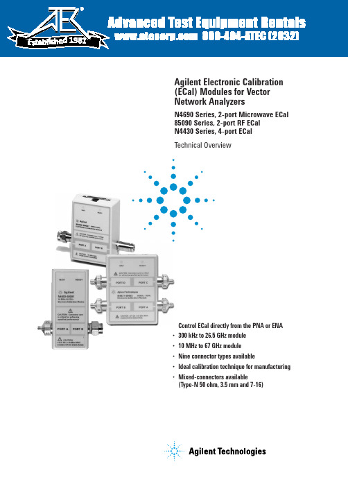
•Control ECal directly from the PNA or ENA •300 kHz to 26.5 GHz module •10 MHz to 67 GHz module •Nine connector types available•Ideal calibration technique for manufacturing •Mixed-connectors available(Type-N 50 ohm, 3.5 mm and 7-16)Agilent Electronic Calibration (ECal) Modules for Vector Network AnalyzersN4690 Series, 2-port Microwave ECal 85090 Series, 2-port RF ECal N4430 Series, 4-port ECalTechnical Overview198125. ENA series consists of E5070/1.6. ENA-L series consists of E5061/2.7.N3381/2/3 have been discontinued.8. PNA-L series consists of N5230.ECal and Agilent Network Analyzer ConfigurationsPNA and ENA SeriesECal modules are controlled directly from the PNA and ENA Series network analyzers. No external PC is required. Simply connect the ECal module to the USB port on the network analyz-er. You can control your calibra-tion from the front panel keys of the PNA Series or automatically by your user program.Calibration configuration using the PNA series3Perform adapter removal calibrations fasterSome analyzers, such as later versions of the 8753 and 8720, offer adapter removal calibration for non-insertable and mixed connector measurement capabil-ity. Since this method requires two full two-port calibrations, it is often time consuming and prone to operator errors. Using ECal to perform the two-port calibrations addresses both of these concerns by reducing the calibration time and the number of connections, simplifying the overall adapter removal process.Perform a User-characterization Normally, when you perform a calibration with an ECal module, the error terms for a calibration are computed using the factory characterization (data) stored in the module. User-characteriza-tion allows you to change the characterization of the module in two ways:• Change the connector configuration: allows you to add an adapter or fixture to the test port of the module and embed the effects into the characterization of the module. The result of the new characterization extends the reference plane from one or more of the module’s test ports to those on the adapter (or fixture).• Modify the state settings: allows you to specify the number of data points (1601 maximum) or other stimulus settings the module uses to perform a cali-bration.When you perform a user-charac-terization, the factory characteri-zation data remains stored in the module’s memory. At calibration, you can select the factory characterization or any of the user-defined characterizations stored in the module. The module can store up to five user-defined characterizations (in addition to the factory characterization data). User-characterization is available with PNA and ENA Series Network Analyzers.41. If the maximum input power is exceeded when calibrating, compression may occur.2. When using the PNA-X, the power level can be increased after calibration with minimal impact on measurement accuracy.3. When mated with male connectors with a 0.77 mm (0.030 in) to 0.86 mm (0.034 in) pin diameter51. When applied power exceeds +9 dBm, calibration results will be degraded from the performance indicated in the table.2. When applied power exceeds –5 dBm, calibration results will be degraded from the performance indicated in the table.3. 3.5 mm modules have precision slotless connectors that guarantee the best calibration accuracy is transferred to your system.61.When applied power exceeds +9 dBm, calibration results will be degraded from the performance indicated in the table.2. When applied power exceeds –5 dBm, calibration results will be degraded from the performance indicated in the table.73. Performance from 9 kHz to 300 kHz is valid only for the E5071C ENA network analyzer with firmware version A.09.10 or higher.4. 9 to 13.5 GHz range not vaild for the N4431A81. When applied power exceeds –7 dBm, calibration results will be degraded from the performance indicated in this table.2. Values based on using the PNA Network Analyzer N5230A Option 240 or 245910Ordering informationSelect an ECal module based on the connector type required and the frequency range of your vector network analyzer (refer to table below).OptionsOption Description00F Replace f-m connectors on ECal module(s) with f-f connectors 00M Replace f-m connectors on ECal module(s) with m-m connectors00A Adds male-to-male and female-to-female adapters (also adds a 5/16” 90 N-cm (8 in-lb) torque wrench to 3.5 mm modules)1A7ISO 17025 compliant calibration A6J ANSI Z540 compliant calibrationUK6Commercial calibration certificate with measured data M0F f-m connectors on ECal module(s)010Four female, 3.5 mm connectors 020Four female, Type-N 50 ohm connectorsECal modules and available options2-portConnector Frequency range ECal module Available options Type model number Type-F300 kHz to 3 GHz85099C 00A, 00F, 00M, UK6, M0FType-N 300 kHz to 9 GHz 85092C00A, 00F, 00M, UK6, 1A7, A6J, M0F,50 ohms mixed-connectorsType-N 300 kHz to 18 GHz N4690B00A, 00F, 00M, UK6, 1A7, A6J, M0F 50 ohmsType-N 300 kHz to 3 GHz 85096C 00A, 00F, 00M, UK6, M0F75 ohms3.5 mm 300 kHz to 9 GHz85093C00A, 00F, 00M, UK6, 1A7, A6J, M0F mixed connectors3.5 mm 300 kHz to 26.5 GHz N4691B 00A, 00F, 00M, UK6, 1A7, A6J, M0F 7 mm 300 kHz to 9 GHz 85091C UK6, 1A7, A6J 7 mm 300 kHz to 18 GHz N4696BUK6, 1A7, A6J7-16 300 kHz to 7.5 GHz 85098C 00A, 00F, 00M, UK6, M0F, mixed-connectors 2.92 mm 10 MHz to 40 GHz N4692A 00A,00F, 00M, UK6, 1A7, A6J, M0F 2.4 mm 10 MHz to 50 GHz N4693A 00A,00F, 00M, UK6, 1A7, A6J, M0F 1.85 mm10 MHz to 67 GHzN4694A00A,00F, 00M, UK6, 1A7, A6J, M0F4-portConnector Frequency range ECal module Available options Type model number 3.5 mm or 9 kHz to 13.5 GHz N4431B010, 020, UK6, 1A7, A6J, mixed-connectorsType-N 50 ohms Type-N 300 kHz to 18 GHz N4432A 020, mixed-connectors 50 ohms 3.5 mm300 kHz to 20 GHzN4433A010Notes:1. Order the 85097B interface module if you will be using ECal with your 8719, 8720, 8722 or 8753. (Please reference the ECal and network analyzer/firmware compatibility table on page 3.) The 85097B con-sists of an interface module and a power supply.2.When using the N469x ECal prod-ucts with the 8720 or 8753 network analyzer families, an adapter cable (8121-1047) is needed. This adapter cable is orderable as an option with the 85097B.1.Performance from 9 kHz to 300 KHz is valid only for the E5071C ENA network analyzer with firmware version A.09.10 or higher.1111.Limits ECal module high frequency to 7.5 GHz.Remove all doubtOur repair and calibration services will get your equipment back to you, performing like new, when prom-ised. You will get full value out of your Agilent equipment through-out its lifetime. Your equipment will be serviced by Agilent-trained technicians using the latest factory calibration procedures, automated repair diagnostics and genuine parts. You will always have the utmost confidence in your measurements. For information regarding self maintenance of this product, please contact your Agilent office.Agilent offers a wide range of ad-ditional expert test and measure-ment services for your equipment, including initial start-up assistance, onsite education and training, as well as design, system integration, and project management.For more information on repair and calibration services, go to:/find/removealldoubt/find/emailupdatesGet the latest information on theproducts and applications you select./find/agilentdirectQuickly choose and use your testequipment solutions with confidence./find/openAgilent Open simplifies the process of connecting and programming test systems to help engineers design, validate and manufacture electronic products. Agilent offers open connectivity for a broad range of system-ready instruments, open industry software, PC-standard I/O and global support, which are combined to more easily integrate test system development.For more information on Agilent Technol-ogies’ products, applications or services, please contact your local Agilent office. The complete list is available at:/find/contactus Americas Canada(877) 894-4414Latin America 305 269 7500United States (800) 829-4444Asia Pacific Australia 1 800 629 485China800 810 0189Hong Kong 800 938 693India 1 800 112 929Japan 0120 (421) 345Korea 080 769 0800Malaysia 1 800 888 848Singapore 180****8100Taiwan 0800 047 866Thailand1 800 226 008Europe & Middle East Austria 01 36027 71571Belgium 32 (0) 2 404 93 40 Denmark 45 70 13 15 15Finland 358 (0) 10 855 2100France 0825 010 700**0.125 €/minuteGermany ************Ireland 1890 924 204Israel 972-3-9288-504/544Italy 39 02 92 60 8484Netherlands 31 (0) 20 547 2111Spain 34 (91) 631 3300Sweden 0200-88 22 55Switzerland 0800 80 53 53United Kingdom 44 (0) 118 9276201Other European Countries:/find/contactusRevised: October 6, 2008© Agilent Technologies, Inc. 2002-2009Printed in USA, February 3, 20095963-3743EWindows ®and Windows NT ®are U.S. registered trademarks of Microsoft Corp.Product specifications and descriptions in this document subject to change without notice.Web ResourcesVisit our Web sites, for additional product information and literature.Electronic calibration (ECal):/find/ecalPNASeries network analyzers:/find/pnaTest and measurement accessories:/find/accessories。
- 1、下载文档前请自行甄别文档内容的完整性,平台不提供额外的编辑、内容补充、找答案等附加服务。
- 2、"仅部分预览"的文档,不可在线预览部分如存在完整性等问题,可反馈申请退款(可完整预览的文档不适用该条件!)。
- 3、如文档侵犯您的权益,请联系客服反馈,我们会尽快为您处理(人工客服工作时间:9:00-18:30)。
规 范
3. 规范
3.1 进水要求
单位 ppm ppmCaCO 3 ppm ppm ppm ppm ppm 进水要求 * 使用 E-Calc 计算 < 1.0 ** < 1.0 @ 最小产水量 ~ 标准产水量 < 0.766 @ 最大产水流量 < 0.5 < 0.05 < 0.01 <1.0 未检出 <1.0 未检出 <5
7.
8.
停机程序 ……………………………………………………………………………………… 15 8.1 E-CELL™ 模块在自动操作模式下停机 …………………™ 模块长期停机 ……………………………………………………………… 15 16 16 16 16 17 17 19 20 20 22 22 22 23 25 25 26 27
极水流 GEWPT 淡水产水 整流器
一小部分淡水供给水流经每个E-CELL™ 系统E-CELL™ 模块极水室,并 且在离开系统后将直接排放的水 GE水处理及工艺过程处理 由E-CELL™系统生产的高纯水 直流电源
人身安全防护措施
2. 人身安全防护措施
在E-CELL™ 模块及本使用手册中可以看到以下象形图
TEA - MK-3Pharm
TEA - MK-3 Mini
** 阅读该部分操作说明书 - 浓水的流量取决于回收率与进水硬度。 注意:E-Cell™模块的进水必须是 RO 产水或同等水质的水。
3.2
产水要求
倘若保证进水满足进水水质要求及按照操作说明对系统进行操作, E-Cell™模块可以生产 16MOhm.cm 的产水 (MK-3, MK-3 Mini) 或者 10 MOhm.cm 的产水 (MK-3 Pharm) 。
象形图
作用 警告!
说明 未经训练人员任何时候都不得使用 E-CELL™ 模块。 在未阅读用 户手册及未接受训练情况下请勿试图操作 E-CELL™ 模块。 若未 按照本手册中的步骤进行操作将有可能导致严重损伤。 E-CELL™ 模块只在高于大气压和 /或低于大气压的真空中工作。 请阅读本手册中的安全步骤。 空气清洁方式不适用于 E-CELL™ 模块。 使用空气清洁方式无法 ™ 清洁或清除 E-CELL 模块中的阻塞物。 随意拆卸 E-CELL™ 模块,拧松或者拆除定位螺栓及其它对 E-CELL™ 模块的不当操作和使用都可能导致严重的人身伤害。 对所有人员在使用化学清洗液的危险方面进行培训。 当有可能 曝露在酸, 腐蚀性物质, 氧化剂或者其它化学品的情况下必须 佩戴橡皮手套, 橡胶防护衣, 面罩和护目镜。 在所有化学品管线上安装法兰防护。
规 范
3.3
参数 产水
E-CELL™模块操作参数
范围 MK-3, MK-3Pharm 7.5 - 20.0 gpm (1.70 - 4.54 m3/h) MK-3 Mini 2.5 - 6.7 gpm (0.57 - 1.52 m3/h) 40 - 104° F (4.4 - 40℃) 60 - 100 psig (3.4 - 6.9 bar) @ 最小流量到标准流量 70 - 100 psig (4.5 - 6.9 bar) @ 标准流量到最大流量 20 - 40 psid (1.4 - 2.8 bar) @ 标准流量 10 - 20 psid (0.7 - 1.4 bar) @ 最小流量 35 - 50 psid (2.4 - 3.4 bar) @ 最大流量 85 - 95% * 最大 400 V 直流 最大 5.2 A 直流
1. 2. 3.
E-CELLTM模块术语表 ………………………………………………………………………… 1 人身安全防护措施 …………………………………………………………………………… 2 规范 …………………………………………………………………………………………… 4 3.1 3.2 3.3 3.4 3.5 进水水质要求 ………………………………………………………………………… 产水水质 ……………………………………………………………………………… E-CELL™ 模块操作参数 ……………………………………………………………… E-CELL™ 模块技术与性能数据 ……………………………………………………… E-CELL™ 安全标准要求 ……………………………………………………………… 4 4 5 5 6 7 7 7 7
参数 TEA( 以 CaCO 3 计 ) 硬度 ( 以 CaCO 3 计 ) 硅 ( 活性硅 ) 硅 ( 活性硅 ) TOC 氯总量 铁 , 锰 , 硫化氢 SDI 15 分钟 油 / 油脂 浊度 氧化剂 色度
NTU APHA
TEA - MK-3
ppm 以 CaCO 3 计 *
< 25 @ 15 gpm / 3.4 m3/h 产水流量 ( 标准产水量 ) < 48.8 @ 7.5 gpm / 1.7 m3/h ( 最小产水量 ) < 15 @ 20 gpm / 4.5 m3/h ( 最大产水量 ) <26 @ 15 gpm / 3.4 m3/h ( 标准产水量 ) <55 @ 7.5 gpm / 1.7 m3/h ( 最小产水量 ) <20 @ 20 gpm / 4.5 m3/h ( 最大产水量 ) <25 @ 5 gpm / 1.14 m3/h ( 标准产水量 ) <49 @ 2.5 gpm / 0.57 m3/h ( 最小产水量 ) <15 @ 6.7 gpm / 1.52 m3/h ( 最大产水量 )
E-CELL™ 模块术语表
1. E-CELLTM 模块术语表
浓水进口 浓水排放 浓水出口 淡水进口 E-CALC
浓水流进入浓水室并以浓水排放方式排出 进入排水管或者回收系统上游的浓水流,其中含有从淡水流中去除 的离子 参见浓水排放 液流流经E-CELL™ 模块并将成为淡水和极水出口 E-Calc电子数据报表[可从GE水处理及工艺过程处理(GEWPT)获得] 计算所有基于供水分析及选定操作工况的E-CELL™ 电子数据交换(EDI) 过程的参数
阻塞或断流将损坏模块。 如果在模块内所有通路都没有液体流经的情况下通电, 必然会损坏模块。 ™ ™ RO 及 E-Cell 之间具有一个开放的系统(例如,水箱、除碳器) ,必须在 E-Cell 之前装配过保安滤器以防止 E-Cell™系统被颗粒物污染。 一般来说,5μm 绝对过滤器或者 1μm 标准过滤器即可。 为满足您所使用系统的 ™ 具体需要, 请咨询通用水处理公司或者您的 E-Cell 系统集成商。 阻塞的一般原因: • PVC 碎屑、 水泥、 粘土或是其他碎片从上游管道或导管进入模块入口, 而此处在使用 E-Cell™系统前没有 安装过滤器。 • 手动阀意外关闭。 给 E-Cell™系统供电或供水之前: • 在给 E-Cell™模块连接供水管道之前必须用经过滤的合格冲洗水将管道系统彻底冲洗干净并且将冲洗 水排放。 因为如果管道内残余的碎屑或其他颗粒物可能对模块导致无法挽回的损害。 • EDI 启动时, 给水泵应该缓慢升压, 从零到稳定的运行压力需要 1-2 分钟以上, 这样做可防止水锤导致 的严重损坏。 在全面供水之前请先缓慢将模块和系统中的空气排尽。 请勿对模块过度加压。 • 确保电流开关及变送器设置正确并且能够正常工作。 • 确保建立了三条水流, 并且所有的安全互锁都经过证明:极水排放流, 淡水产水流以及浓水排放流。 • 核实没有任何形式的氯或氧化剂进入 E-Cell™模块。 进水必须符合进水水质要求。 • 若在进水硬度 >1ppm (以碳酸钙计) 或者二氧化硅 >1ppm,或者其他进水水质指标没有达到进水水质 ™ 要求,E-CELL 模块将可能被损坏,除非采取特殊防护措施。 如果进水硬度或者二氧化硅超标,定期的 酸洗和对 RO 产水进行软化是必需的。 [ 检查公布的要求是 0.5ppm 还是 1ppm。 ] 塑料连接件和管口可更换。 请小心操作。 在开始操作前请务必用手紧这些固零件。
4.
电气 …………………………………………………………………………………………… 4.1 E-CELL™ 模块最大功率要求 ………………………………………………………… 4.2 工作电流 ……………………………………………………………………………… 4.3 E-CELL™ 模块电气设计 ………………………………………………………………
电击危险 直流电 (DC)
E-CELL™ 模块充电时有高压危险。 当需要在 E-CELL™ 模块附近 工作时请先断开直流电源。 使用 V 或 A 指示直流电压、 电流或是使用开启 / 关闭符号进行 标示。
人身安全防护措施
张贴如下警告页于您的 E-CELL™ 系统
警告 防止模块损坏
如未遵循以下防护措施, 将不享有保修服务。
5. 6.
机械及水力学要求 …………………………………………………………………………… 8 收货及安装 …………………………………………………………………………………… 6.1 收货 …………………………………………………………………………………… 6.2 搬运 …………………………………………………………………………………… 6.3 E-CELL™ 模块保存 …………………………………………………………………… 6.4 安装 …………………………………………………………………………………… 6.5 排水通风 ……………………………………………………………………………… 启动 …………………………………………………………………………………………… 7.1 综述 …………………………………………………………………………………… 7.2 启动 …………………………………………………………………………………… 7.3 逆流与顺流 …………………………………………………………………………… 7.3.1 为系统充液并开启淡水流 …………………………………………………… 7.3.2 设置浓水流,极水流及淡水流 ……………………………………………… 7.3.3 确认所有的流量及压力 ……………………………………………………… 7.3.4 启动直流电源 ………………………………………………………………… 7.3.5 将冲洗水流转换为产水流 …………………………………………………… 9 9 9 9 9 10 11 11 11 11 13 13 13 14 14