T1201刷机方法
主板一键刷机使用说明书

操作步骤
1.将刷机文件拷贝到SD卡(根目录下)
包含的文件为:embv210_root.img ,u-boot.bin ,zImage
2.将SD卡插入主板(确保SD卡位置插放正确)
3.打开主板一键刷机工具,首次会弹出端口设置界面。
4.端口号根据自己机子的实际串口来设置,波特率必须为
115200,其他设置默认。
5.接上主板电源,用串口线将主板与pc连接。
主板开机
6.主板刚开机时迅速按软件上的“回车”按钮(并非pc键盘的
回车)直到出现SMDKV210 #
7.接着点击“文件检测”。
出现如下画面为检测完成:
8.下载需要的文件
a:更新uboot:
b:更新zimage
C:更新ststem
完成。
注意事项:
1.建议使用台式机使用更新工具来完成。
2.如果主板开机会重启,建议全部格式化之后,然后必须接着步骤6到结束。
(如果格式化
之后,不接着文档中步骤6开始执行,否则后面主板烧写工作要跳线为usb模式进行操作,步骤比较烦琐。
)
3.如果格式化主板,文件里面一定要存在uboot.Bin 。
文件检测也会检测这些文件的存在。
4.更新过程中,请勿将SD卡拔下来。
三星Galaxy S2 HD LTE E120l刷机教程

三星Galaxy S2 HD LTE E120l刷机教程三星Galaxy S2 HD LTE 怎样刷机?今天在这整理一篇简单的三星E120l刷机教程。
有需要的朋友们可以参看。
该篇教程讲解详细,操作起来容易,极其简单!快快体验一番!第一步操作:连接手机设备并安装驱动用一根稳定安全的数据线把手机和电脑连接起来,再打开完美刷机软件连接上手机设备,需打开手机的USB调试。
连接手机首次刷机的用户,软件会为您安装手机驱动,这样能保证成功完成刷机。
驱动修复时,请按照提示断开手机与电脑的连接,点击我已断开手机按钮驱动就开始修复。
断开USB连接驱动修复完成了,再次打开USB调试,点击确定按钮开始准备刷机了。
驱动安装完成第二步操作:自由选择ROM刷机一,连接好手机设备,直接选择软件提供的ROM包,点击一键刷机。
二,点击浏览按钮,导入下载好的Rom包,点击开始刷机按钮,进行刷机。
三星E120l刷机教程温馨提示:下载的ROM包一定要适用于自己的手机,不然会造成刷机失败的结果。
三,点击软件的ROM市场,条件性选择自己喜欢的ROM包,然后直接刷机即可。
第三步操作:三星E120l刷机进行中刷机开始了,在刷机运行中要花费几分钟的时间,请耐心等待。
等待过程中,请不要对手机做任何操作,以免出现多种错误,导致刷机失败从而损害自己的手机。
刷机中第四步操作:刷机成功完成成功完成刷机了。
成功之后,断开手机与电脑的连接,这样比较安全。
刷机过后,第一次开机会需要几分钟的时间,要耐心等。
刷机成功三星Galaxy S2 HD LTE E120l刷机就是这样了,只要依照教程操作就可以安全为自己的手机换上新的安卓系统。
这个教程极其简单,真心为小白们提供帮助了!体验刷机之前,请认真阅读此篇教程,根据提示进行操作。
蓝魔音悦汇T12刷机(图文教程) 小猪版
第一种方法:
注意:机器首次使用时必须按此种方式操作
1.将机器关机
如果在开机状态下,长按关机键关机.
2.按住ok键,然后将MP3通过USB接口
与电脑连接。
(直到电脑发现新硬件)
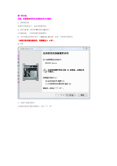
3.首次电脑会找到并显示“ RK28usb Device”信息,并要求安装驱动(如果已经安装过驱动的,直接跳过3、4步),
如下图
4.安装产品驱动程序
①选择从指定位置安装驱动,点击“下一步”
②点击“浏览”,在文件夹中找到“Driver”目录(对应固件解压路径),点击“确定”安装程序文件
③程序安装完成,屏幕出现如下图
点击“完成”.
5..双击RK28Upgrade.exe
6.右下脚出现如下
Ps:电脑未发现设备请重练
7.点升级
8.耐心等待升级结束
注意事项
1.刷机前请备份.
2.刷完固件第一次听歌请不要使用恢复播放直接选歌播放..下次可以使用恢复播放.
3.如果刷完机,发现原来可以播放的视频音频小说无法播放。
请重刷并且勾上强制擦除。
线刷宝刷机的方法

线刷宝刷机的方法现在手机和笔记本电脑越来越普及,使用线刷宝刷手机系统能够有效的帮助用户避免刷机变砖。
下面是店铺为大家整理的关于线刷宝刷机的方法,一起来看看吧!线刷宝刷机的方法于其他刷机软件来说,线刷宝的优势比较明显。
对没有ROOT,SD卡没有空间的手机也能也能安全刷机,真正做到化繁为简,一键智能刷机。
此外,线刷目前是官方所唯一认证的刷机方式,线刷宝所有ROM包都基于厂商原包,特供官方纯净ROM、第三代安全稳定ROM、超级精简ROM三种版本,提供最干净、整洁的官方ROM,做到安全有保障,不必再担心其他第三方放置扣费软件。
那么线刷宝刷机有什么优势呢?先给各位介绍一下有几种刷机的方式吧,其实刷机一共有四种方式,分别是软刷、卡刷、线刷和厂刷四种方式。
产品特点编辑1.手机官方采取唯一指定升级方式,比卡刷更稳定、更彻底、更安全;2.线刷无需考虑手机内存容量、手机电量等因素;3.手机没有ROOT也能刷机;4.全智能进入刷机模式,系统智能识别,没有专业知识也能刷机;5.最重要的一点:线刷是救砖必备良药。
功能介绍智能线刷线刷宝采用全智能刷机方式,通过USB数据线连接个人计算机,在个人计算机上使用刷机软件进行刷机。
对没有ROOT,SD 卡没有空间的手机也能也能安全刷机,真正做到化繁为简,一键智能刷机。
线刷目前是官方所唯一认证的刷机方式。
一键救砖线刷工具是救砖必备。
线刷宝提供一键救砖功能,让无法开机、白屏、花屏、定屏等手机,在能够进入刷机模式的情况下从砖头还原成手机。
ROM中心线刷宝ROM中心,目前提供三种版本的ROM包:官方原版ROM:100%厂商官方系统,回归安卓手机最初系统,解决售后难题;安全优化版ROM:基于官方版,引进安狗狗第三代智能手机系统,无其它插件添加,安全稳固,确保手机绝不中毒,超级省电!ROOT安全版ROM:开机自动获取ROOT权限,无需进行手动操作。
刷机流程1.下载安装线刷宝客户端从下载站下载线刷宝,安装线刷宝。
索爱MT15i刷机教程,安卓刷机root 体验

索爱MT15i刷机教程,一键刷机、root 体验教程
刷前准备工作:
1、刷机前请事先做好系统备份,养成良好的备份习惯,防止个人数据丢失
2、刷机前请备份好联系人、短消息、应用软件等其他个人资料
开始刷机:
一、解锁:
可使用甜椒刷机助手一键解锁,下载地址(),下载完成后安装。
1.安装好后进入设置-应用程序-开发,打开USB调试选项。
2.将手机与电脑相连接,打开甜椒刷机助手软件。
3.此时软件自动下载安装驱动,安装完成后,软件显示首页图
4.此时,进入实用工具窗口,打开临时Root或者永久Root 工具,进行一键解锁,注意阅
读解锁须知信息。
点击同意,待约一分钟左右,显示ROOT成功界面。
二、刷机:
1. 从ROM 商城选择想要升级的ROM 包,进行下载,或者自行从论坛下载ROM 包也可以。
(注意:ROM 包必须下载完整,并为.ZIP 格式)
2. 将下载好的ROM 包拖动到ROM 地址栏,点击“开始刷机”即可。
软件自动进入刷机阶段
刷机完成后,提示,刷机成功,点击返回键。
待约2分钟左右,手机自动加载并重新连接软件。
从首页查看,已成功升级到安卓2.3.7
整个刷机过程仅需要10分钟左右,就可一键完成。
甜椒提供的多款实用小工具
甜椒提供的知识库,有各款机型救砖教程及使用帮助
甜椒提供的ROM商城,有各款机型救砖教程及使用帮助。
线刷流程操作方法
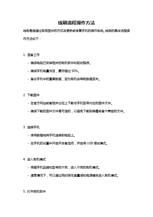
线刷流程操作方法线刷是指通过刷写固件的方式来更新或修复手机的操作系统。
线刷的具体流程操作方法如下:1. 准备工作- 确保电脑已安装相关的刷机软件和驱动程序。
- 确保手机电量充足,最好超过50%。
- 备份手机中的重要数据,因为刷机会导致数据丢失。
2. 下载固件- 在官方网站或者相关论坛上下载与手机型号对应的固件文件。
- 确保下载的固件文件是可信的,以避免下载到病毒或者不兼容的文件。
3. 连接手机- 使用数据线将手机连接到电脑上。
- 在手机的设置中开启开发者选项,并启用USB调试模式。
4. 进入刷机模式- 根据手机品牌和型号的不同,进入不同的刷机模式。
- 通常情况下,可以通过同时按住音量减和电源键来进入刷机模式。
5. 打开刷机软件- 打开已安装的刷机软件。
- 在软件中选择刷机选项,并选择下载的固件文件。
6. 开始刷机- 点击开始刷机按钮,开始刷机过程。
- 刷机过程中,不要断开手机与电脑的连接,也不要进行其他操作。
7. 等待刷机完成- 刷机过程需要一定的时间,具体时间根据固件的大小和手机的性能而定。
- 等待刷机过程完成,期间不要操作手机或电脑。
8. 刷机完成- 当刷机过程完成后,刷机软件会提示刷机成功。
- 此时可以拔出手机与电脑的连接,然后重启手机。
注意事项:- 刷机只能在相应的手机型号上进行,不同品牌和型号的手机刷机方法可能不同。
- 刷机有风险,如果操作不当可能导致手机变砖或者失去保修。
- 刷机前务必备份手机中的重要数据,以防刷机过程中数据丢失。
- 刷机过程中,不要进行其他操作,以免干扰刷机过程的进行。
刷系统教程
刷系统教程刷系统是一种常见的操作,用于修复或更新电脑、手机、平板等设备的操作系统。
本文将为您介绍刷系统的操作步骤和注意事项。
刷系统之前,首先需要备份重要的文件和数据。
因为刷系统过程中,会清除设备上的所有数据,防止数据丢失。
第一步,下载刷机工具。
根据需要刷的设备,选择对应的刷机工具。
常见的刷机工具有手机助手、第三方刷机工具等。
确保下载的刷机工具是正规渠道获取的,以免下载到恶意软件造成设备损坏。
第二步,连接设备到电脑。
使用数据线将设备连接到电脑,并确保电脑能够正常识别到设备。
如果无法正常连接,可以尝试更换数据线或调试设备的USB连接设置。
第三步,打开刷机工具。
运行下载好的刷机工具,选择相应的操作系统版本和设备型号。
在刷机工具的界面上通常会有详细的说明和操作指南,按照指引进行操作。
第四步,进入刷机模式。
根据设备的型号和品牌,刷机模式的进入方式可能有所不同。
通常,可以通过同时按住设备的特定按键(如音量加键、音量减键、电源键等)进入刷机模式。
具体的进入方式可通过查阅设备的说明书或在网上搜索获得。
第五步,开始刷机。
在刷机工具的界面上,点击开始刷机或类似按钮,等待刷机过程完成。
期间,切勿断开设备与电脑的连接,以免造成刷机失败或损坏设备。
第六步,等待刷机完成。
刷机过程可能需要一些时间,具体时间长短取决于设备型号和操作系统大小。
在刷机过程中,请耐心等待,并避免中断。
第七步,重启设备。
刷机完成后,刷机工具通常会提示用户重启设备。
在重启前,确保设备已经断开与电脑的连接,然后按照刷机工具的指引重启设备。
刷系统虽然是一种常见的操作,但仍然有些注意事项需要注意。
首先,刷机操作有一定风险,可能导致设备无法正常启动或出现其他问题。
因此,在刷机之前,请充分了解设备的刷机风险并权衡利弊。
其次,刷机操作可能会违反设备的保修政策,导致设备的保修失效。
因此,在保修期内,最好避免刷机操作。
最后,刷机过程中,请确保设备有足够的电量,以免刷机过程断电导致设备损坏。
Aeroflex T1201 产品说明书
OPERATION MANUALT1201VOR, ADF, ILS DISCRETE FUNCTIONINTERFACE UNITMANUAL NUMBER:06-1201-01E6-1201-01REVISION:0DATE:03/26/2007WARNING: INFORMATION SUBJECT TO EXPORT CONTROL LAWSThis manual may contain information subject to the International Traffic in Arms Regulation (ITAR) or the Export Administration Regulation (EAR) which may not be exported, released, or disclosed to foreign nationals inside or outside of the United States without first obtaining an export license. A violation of the ITAR or EAR may be subject to a penalty of imprisonment and/or fines under 22 U.S.C.2778 of the Arms Export Control Act or section 2410 of the Export Administration Act. Include this notice with any reproduced portion of this document.This document is proprietary to Aeroflex, and is not to be reproduced or otherwisedisseminated without the written consent of Aeroflex.400 New Century Parkway – New Century, Kansas – 66031Telephone: (800) 237-2831 / (913) 764-2452 Fax: (913) 782-5104ELECTROSTATIC DISCHARGE GENERAL WARNINGS FOR ALL EQUIPMENTCAUTION:THIS EQUIPMENT MAY CONTAIN ELECTROSTATIC DISCHARGE (ESD) SENSITIVE COMPONENTS. TO PREVENT ESD SENSITIVE EQUIPMENT FROM POSSIBLEDAMAGE, OBSERVE THE FOLLOWING PRECAUTIONS WHEN HANDLING ANY ESDSENSITIVE COMPONENTS, OR UNITS CONTAINING ESD SENSITIVECOMPONENTS:a. Maintenance or service personnel must be grounded though a conductive wrist strap, or a similargrounding device, using a 1 MΩ series resistor for equipment protection against static discharge, and personal protection against electrical shock.b. All tools must be grounded (including soldering tools) that may come into contact with theequipment. Hand contact will provide sufficient grounding for tools that are not otherwisegrounded, provided the operator is grounded through an acceptable grounding device such as a wrist strap.c. Maintenance or service of the unit must be done at a grounded, ESD workstation.d. Before maintenance or service of the equipment, disconnect all power sources, signal sources,and loads connected to the unit.e. If maintenance or service must be performed with power applied, take precautions againstaccidental disconnection of equipment components. Specifically, do not remove integratedcircuits or printed circuit boards from equipment while the equipment has power applied.f. All ESD sensitive components are shipped in protective tubes or electrically conductive foam.The components should be stored using the original container/package when not being used or tested. If the original storage material is not available, use similar or equivalent protectivestorage material.g. When ESD sensitive components are removed from a unit, the components must be placed on aconductive surface, or in an electrically conductive container.h. When in storage or not being repaired, all printed circuits boards must be kept in electricallyconductive bags, or other electrically conductive containers.i. Do not unnecessarily pick up, hold, or directly carry ESD sensitive devices.Failure to comply with these precautions may cause permanent damage to ESD sensitive devices. This damage can cause devices to fail immediately, or at a later time without apparent cause.Aeroflex Operation ManualREVISION HISTORY BY DRAWING NUMBER MANUAL: T1201 VOR, ADF, ILS Discrete Function Interface UnitREVISION: 0 – March 26, 2007REV. REV._LEVEL DRAWING NO. LEVEL NO.DRAWINGTable of Contents 00Section I 00Section II 00Section III 00Section IV 00Section V 00Aeroflex Operation ManualTABLE OF CONTENTSSECTION IGENERAL INFORMATIONSECTION PAGE NUMBER 1.1 INTRODUCTION...............................................................................................1-11.2 EQUIPMENTDESCRIPTION............................................................................1-1CHARACTERISTICS...................................................................1-11.3 TECHNICAL1.3.1 General..............................................................................................................1-1Simulator.............................................................................................1-11.3.2 Antenna1.4 UNITSACCESSORIES REQUIRED........................................................1-2ANDEQUIPMENT..................................................................................1-21.5 OPTIONALINFORMATION................................................................................1-31.6 RELATEDSECTION IIINSTALLATIONINFORMATION...............................................................................2-12.1 GENERAL2.2 UNPACKING AND INSPECTION OF EQUIPMENT.........................................2-12.3 EQUIPMENT SETUP........................................................................................2-1SECTION IIIOPERATION3.1 INTRODUCTION...............................................................................................3-1FUNCTIONS...................................................................................3-13.2 CONTROLFront Panel........................................................................................3-1–3.2.1 Control–Rear Panel.........................................................................................3-53.2.2 ControlSECTION IVTHEORY OF OPERATIONSCIRCUIT THEORY..........................................................................4-14.1 GENERALAmp Board..............................................................................................4-14.1.1 AudioSimulator Board..................................................................................4-14.1.2 AntennaSECTION VMAINTENANCEINFORMATION......................................................................5-15.1 MAINTENANCESECTION IGENERAL INFORMATION1.1 INTRODUCTIONThis manual contains information relative to the physical, mechanical and electrical characteristics of the Aeroflex Model T1201 Discrete Function Interface Unit, (DFIU) PN: 01-1201-00.1.2 UNITS AND ACCESSORIES SUPPLIEDTh T1201 DFIU is designed to operate and test ARINC 700 Series ILS (ARINC 710), VOR/MB (ARINC 711) and ADF (ARINC 712) Line Replaceable Units. Power control and protection, as well as all necessary discretes and monitoring points are provided. Magnetic overlays for each applicable LRU are available which connect either the ILS, VOR, or ADF receivers to the T1202. ARINC 429 transmissions and reception to and from the LRU’s is provided by the companion T1200 Control Display Unit (CDU) via a rear panel interface connector. The T1201 DFIU also provides an ATE interface port and a special Collins Radio Interface similar to RS-232. A self-contained Antenna Simulator provides the sense and loop signals required for testing ADF receivers.1.3 TECHNICAL CHARACTERISTICS1.3.1 GENERALKg)(6.82lbs.Weight: 15cm)(30.86in.Height:12.15(48-26cm)in.Width:19.00Depth : 9.00 in. (22-86 cm)Power Requirements : 27.5VDC @ 2 AmpsAmps2155VAC/400Hz@Operating Temperature : +10 to +45 deg. C1.3.2 ANTENNA SIMULATOR:KHz190-1750RangeFrequencyInput Impedance : 50 Ohms (unbalanced)Output Impedance : 78 Ohms +/- 5%Sense Channel OutputAttenuationAmplitudeinputtheFactor (Effective Height) .03timesLoop Channel OutputsAttenuation Factor : .023 times input at 190 KHzatKHz577input.038times1750KHzattimesinput.023Accuracy : +/- 2 dBLoop Output AmplitudeMatch at 45° Relative.25dB: +/-BearingAntenna Mount Top/BottomFunction : Top - Sine & Cosine in phase first quadrantCosine180° out of phase first quadrant&Bot-Sine1.4 UNIT AND ACCESSORIES SUPPLIEDThe Aeroflex Model T1201 DFIU, PN: 01-1201-00, consists of the main test panel and the following accessories:ITEM DESCRIPTION P/N1 T1201 CD Operation Manual E6-1201-012 115V/400Hz Power Cable 55-2406-001.5 OPTIONAL EQUIPMENTThe following items are available as optional equipment with the T1201 DFIU. They must be ordered separately.ITEM DESCRIPTION P/N1 T1201-01 VOR/MB Interface Cable 55-1201-012 T1201-02 ILS Interface Cable 55-1201-023 T1201-03 ADF Interface Cable 55-1201-034 Test Point Overlay – ADF-700 58-1169-005 Test Point Overlay – VOR-700 58-1169-016 Test Point Overlay – ILS-700 58-1169-021.6 RELATED INFORMATIONFor information regarding the T1201-01 (VOR/MB), T1201-02 ILS and T1201-03 (ADF), T1201-04 (MMR) Interface Cables, refer to their individual operation manuals. When referencing the T1201-04 (MMR) cable also consult the associated test unit the MMR Test Fixture, Manual number 06-0997-00. The part numbers for these Interface Cable manuals are as follows :INTERFACE CABLE MANUAL P/NT1201-01 C6-1201-01T1201-02 C6-1201-02T1201-03 C6-1201-03T1201-04 C6-1201-04SECTION IIOPERATION2.1 GENERAL INFORMATIONThis section contains information relating to the unpacking, inspection and setup of the T1201 DFIU accessories.2.2 UNPACKING AND INSPECTION EQUIPMENTCarefully remove the T1201 DFIU and accessories from the packing box. Make a visual inspection of the unit for evidence of damage incurred during shipment. If a claim for damage is to be made, save the shipping container to substantiate the claim. When all equipment has been unpacked, return the packing material to the container for future use in storing or shipping the equipment.2.3 EQUIPMENT SETUPThe T1201 DFIU may be installed free standing on a workbench table top or mounted in a 19-inch equipment rack using the integral rack mounting ears.Connect 28VDC power to the banana jack/binding posts (J16) at the rear of the T1201.Connect 115VAC/400Hz power to the receptacle (J5) at the rear of the T1201 using the power cordJPN: 55-2406-00, provided with the test set.* * * NOTE * * *The power cord provided is left unterminated at one end to accommodate wiring to your own particular 115VAC supply. The wires should be connected as follows :BLK Wire – 115VAC-400Hz HotWHT Wire – 115VAC/400Hz NeutralGRN Wire – 115VAC/400Hz GroundConnect a T1200 CDU to the T1200 Interface connector (J4) at the rear of the T1201 using the T1200 DFIU Cable, PN: 55-2401-00, supplied with the T1200.The LRU is connected to the T1201 via the T1201-01 (VOR/MB), T1201-02 (ILS) or T1201-03 (ADF) Interface Cable, PN: 55-1202-01, -02,or –03, respectively. Install the appropriate magnetic test point overlay (see section 1.5) to the T1201’s test point field on the front panelIMPORTANTRefer to the appropriate Component Maintenance Manual (CMM) to test procedure for additional test equipment set up procedures.SECTION IIIOPERATION3.1 INTRODUCTIONThis section contains the basic operating procedure for the T1201 DFIU.3.2 CONTROL FUNCTIONSThe T1201 provides all the necessary signals for testing the ARINC 700 Series VOR, ILS and ADF Navigation Systems. The following is a description of each of the controls provided on the DFIU.NOTESome additional controls may be installed on the LRU Interface Cables.3.2.1 CONTROLS – FRONT PANEL (Figure 3-1)(1) DFIU POWER ON/OFF Switch (S18) The T1201 power requirements are provided by anexternal 28VDC source connected to the T1201through a set of banana jack/binding posts (J16) onthe rear panel. The power to the DFIU is turned ONor OFF with a DPST toggle switch.(2) DFIU POWER Fuse (F2) Provides over-current protection for the T1201circuitry.internal(3) DFIU POWER Lamp (DS5) Illuminates when the DFIU 28VDC power isswitched on by S18.(4) UUT POWER ON/OFF Switch (S17) The Unit Under Test power requirements areprovided by an external 115VAC/400Hz sourceconnected to the T1201 through a 3-conductorpower receptacle (J5) on the rear panel. The powerto the UUT is turned ON or OFF with a DPST toggleswitch.(5) UUT POWER Fuse (F1) Provides over-current protection for the unit undertest.(6) UUT POWER Lamp (DS4) Illuminates when the UUT 115Vac/400Hz power isswitched on with S17.(7) CURRENT MONITOR Jacks (J12 & J13) These test jacks allow the user to calculate thecurrent drawn by the UUT by measuring the ACvoltage dropped across a precision 1 ohm resister(R1) in series with the connection to the UUT powerinput (1 volt + 1 amp).(8) LRU AC OUT Jacks (J14 & J15) These test jacks allow the user to monitor the115VAC output from the UUT (VOR & ILS LRU’Sonly).(9) LRU Connector (J1) 156-pin DL connector used to connect with the VOR,ISL, and ADF LRU Interface Cables, i.e. T1201-01,T1201-02 and T1201-03.(10) 429 INPUT BUS Jacks (J203 & J204) Two ¼” stereo phone jacks allow monitoring of thetwo ARINC 429 output buses from the UUT.(11) 429 OUTPUT BUS Jacks (J205 & J206) Two ¼” stereo phone jacks allow monitoring of thetwo ARINC 429 output buses from the UUT.(12) DATA SOURCE Switch (S11) Controls the discrete input pin of the UUT forselecting either ARINC 429 input port A or B.(13) RCVR AUDIO OUT Jacks (J10 & J11) Allows monitoring of the VOR, ILS and ADFReceiver audio outputs.(14) SDI CODE Switch (S16) Allows changing the SDI input straps to eachpossible SDI code (0-3).(15) AUDIO LOAD Switch (S15) Allows selecting various loads for the VOR, ILS orADF audio outputs. The AMP position connects theaudio output to the internal amplifier and speaker.Control Controls the volume of the speaker.(16) VOLUME(17) A/G LOGIC Switch (S10) Controls the AIR/GROUND discrete input to theUUT. The input is connected to ground on the ONposition and is open in the OFF position.(18) FUNC TEST DISC Switch (S9) Controls the FUNCTION TEST discrete in put to theUUT. The input is connected to ground in the ONposition and is open in the OFF position.(19) TEST POINT Field Provides monitoring capability for the sixty pincorresponding to the top plug of the LRU ARINC 600connector. Magnetic overlays are available whichdefine each point for user convenience.(20) TUNE FUNCTION TEST Switch (S1) Controls the TUNE/FUNCTION TEST INHIBITdiscrete input (MP1C) on the ILS Receiver. Theinput is connected to ground in the ON position andis open in the OFF position.(21) LOC/GS DATA Switch (S12) Allows connecting or disconnecting the “LOC/GSInterrupt Data Program pin” (MP3A) to the “LOC/GSData Control Common” (MP3B) on the ILS Receiver.(22) SPEAKER (LS101) A 45 ohm speaker for reproducing the receiveraudio from the UUT.(23) INNER MARKER Lamp (DS1) White lamp which illuminates when the Inner (Fan)Marker output from the Marker Beacon Receiverlow.goes(24) MKR AUDIO LOAD Switch (S14) Allows selecting various loads for the MarkerBeacon Receiver audio output. The AMP positionconnects the audio output to the internal amplifierspeaker.and(25) MIDDLE MARKER Lamp (DS2) Amber lamp which illuminates when the MiddleMarker output from the Marker Beacon goes Low. (26) MKR AUDIO OUT Jacks (J8 & J9) Allows monitoring of the Marker Beacon Receiveroutput.audio(27) OUTER MARKER Lamp (DS2) Blue lamp which illuminates when the Outer Markeroutput from the Marker Beacon Receiver goes low. (28) SENSE Switch (S7) Controls the Hi/Lo Sensitivity discrete input (MP9D)on the Marker Beacon Receiver. The input isconnected to ground in the HI position and is open inthe LO position.(29) INHIBIT Switch (S8) Controls the Marker Function Inhibit discrete input(MP2D) on the Marker Beacon Receiver. The inputis grounded in the ON position and is open in theposition.OFF(30) QEC STRAP Switch (S2-S6) Five toggle switches control the Quadrantal ErrorCorrection inputs to the ADF Receiver. Each inputis connected to the “QEC COMMON” pin (MP9C) inthe CLOSED (DOWN) position and is open in theUP position.(31) SIMULATED BEARING Control (B1) Planetary drive which controls the angular setting ofthe internally mounted goniometer. The goniometercontrols the sine and cosine ADF antenna inputs tothe ADF Receiver.(32) ADF Antenna Connector (J17) 16 pin connector used to mate with the ADFAntenna connector on the T1201-03 ADF InterfaceCable.(33) RF INPUT Connector (J301) BNC connector used to input the RF signal to theADF Antenna Simulator for producing the sense andloopsignals.(34) ANTENNA MOUNT Switch (S13) Controls the Antenna Mount Top/Bottom discreteinput (MP13C) on the ADF Receiver. The input isconnected to ground in the TOP position and is openin the BOTTOM position. Also used to cause a 108°phase reversal of the sine output from the ADFSimulator.AntennaFig. 3-1: T1201-Controls – Front Panel3.2.2 CONTROLS – REAR PANEL (Fig. 3-2)(1) 24VDC Power Input Jacks A set of banana jack/binding post used to connectthe DFIU to a 24VDC power source.(2) 115VAC/400Hz Power Receptacle (J5) Used to connect the DFIU to a 115VAC/400Hzpower source via the detachable 3-conductor powercord.(3) REMOTE SELECTOR Switch This switch has no current function and is notoperational.(4) T1200 INTERFACE Connector (J4) A 37-pin female D connector used to interface theDFIU to a T1200 CDU.(5) COLLINS TEST Connector (J3) A 25-pin female D connector used to gain access tovarious test points from the UUT top plug. SeePN: 02-1201-00 for wiring information.(6) ATE INTERFACE Connector A 96-pin DL connector wired to the DFIU’s test pointboard and to the LRU interface connector. It is alsowired to several monitor points on the DFIU whichprovide additional ATE connections not covered bythe test point board. See PN: 02-1201-00 forinformation.wiringFig. 3-2 ; T1201 Controls – Rear PanelTHEORY OF OPERATION4.1 GENERAL CIRCUIT THEORYSome active circuit is contained on printed circuit boards within the T1201. The following is a brief description. 4.1.1 AUDIO AMP BOARDThe Audio Amp Board, PN: 20-5573-00, is mounted to the inside of the front panel beside the Test Point Board. It is used to provide the selectable load for the receiver’s audio output and to provide a variable amplified output to drive the panel mounted speaker.4.1.2 ANTENNA SIMULATOR BOARDThe Antenna Simulator Board, PN: 20-5616-00, is mounted to the inside of the front panel just above the power switches. It is used to drive the sense and loop antenna of the ADF Receiver.The sense and loop outputs are derived from an RF source (190-1750 KHz) applied at the RF INPUT BNC Connector (J303). The input impedance is approximately 50 ohms.The signal level at the sense output is determined by voltage divider R309 and R310, transformer T305 and series resistor R311.The sine and cosine loop output signals are the result of coupling the RF signal through a goniometer, whose angular position is determined by the rotational placement of a graduated planetary driver mechanism attached to its shaft. Amplitude calibration is accomplished with gain adjustment potentiometers R313 (COS channel) andR314 (SIN channel).MAINTENANCE5.1 MAINTENANCE INFORMATIONTo assist in the maintenance of the Aeroflex Model T1201 Discrete Function Interface Unit, bills of material, assembly drawings, schematics and a test procedure are included in the T1201 Maintenance Manual (P/N 06-1201-00 for hard copy, E6-1201-00 for CD) available separately from Aeroflex.。
T1201 SD卡升级步骤
2)插入电池的时候,按住拨号键和电源键,将会启动T 卡升级程序(如果是首次插入电池,这个时候
需要等上30S 时间果断电或失败,重复升级即可;
2)如果 bl_update 目录下存在多个pac 文件(升级包是打包成以.pac 结尾的文件名),将会提示“Too
many pac file”;
3)如果找不到 pac 文件,将会提示“No pac file in bl_update”。
重要说明:江苏常州锁卡定制的要选择对应的锁卡定制升级包,不可以升级通用版本的升级包。
【升级步骤】
1. 将 SD 卡格式化或删除SD 卡中的文件;
2. 在 SD 卡上新建一个文件夹命名为“bl_update”,将pac 文件拷入该文件夹bl_update 里;
3. 升级方法分 2 种:
迈科云盒T11刷机成安卓系统
迈科云盒T11成功刷机成安卓系统工具:rk3128刷机工具rk3128精简4.44版固件刷机后遥控器正常使用,软件安装就像手机一样随心所欲,只是年月日显示不能同步,但自己的硬件可以自己说了算,还有什么比这更令人欣慰的!下载文件以后,解压,会得到一个名为“Release_DriverAssitant”的文件夹,打开后双击DriverInstall根据提示安装一下(如下图B)。
安装驱动以后,机顶盒连接电脑会自动被识别,否则无法识别也无法刷机,第一次刷机需要安装一下驱动程序,以后无需再次安装。
图A图B【线刷步骤】1、打开AndroidTool,如图1图12、打开“升级固件”,点击“固件”,然后选择下载到的固件包(如图2),固件加载以后会显示固件版本等基础信息(如图3)图2图33、用双公头USB数据线一端连接电脑,然后用牙签或铁丝顶住T11机顶盒两个USB接口中间的复位键不松手,然后把USB数据线的另一端插入机顶盒上靠近网口的那个USB接口,此时,刷机工具界面会提示“发现一个LOADER设备”(如图4),此时可松开复位键,选择刷机工具上的“升级”,开始进入刷机过程(图5)图4图54、刷机过程大约要持续2-3分钟,首先从电脑中把固件刷入机顶盒(图5),固件刷入完毕以后,会进行固件的校验(图6),校验通过以后,量产工具会重启一次机顶盒,重启以后自动断开机顶盒(如图7)。
图6图75、显示重启设备成功以后,可以把USB数据线从机顶盒上移除,关闭AndroidTool 刷机工具,【注意事项】1、如果线刷使用的是台式电脑,请把USB线接入台式电脑机箱后边的USB接口以保证稳定供电,尽可能移除除了鼠标键盘以外的其他所有USB设备。
2、线刷不需要给机顶盒接电源线。
- 1、下载文档前请自行甄别文档内容的完整性,平台不提供额外的编辑、内容补充、找答案等附加服务。
- 2、"仅部分预览"的文档,不可在线预览部分如存在完整性等问题,可反馈申请退款(可完整预览的文档不适用该条件!)。
- 3、如文档侵犯您的权益,请联系客服反馈,我们会尽快为您处理(人工客服工作时间:9:00-18:30)。
华为T1201刷机方法
前几天入手一台华为T1201的移动3G合约机,149元送249话费,活动超火暴。
在网上找软件突然发现这款手机既然能刷机,几经折腾特把刷机经验分享给大家。
准备:下载T1201的刷机包和刷机工具。
地址:
/file/id_2581382719079664.html
步骤1. 安装手机驱动,打开提供的driver_x86文件夹,安装如下图所示的DPInst.exe文件;
步骤2. 安装完驱动之后,双击可执行程序DLoaderR.exe,出现如下图所示程序;
步骤3:点击设置按钮(左一),请选择软件包里面*.pac文件的路径。
选好以后,在程序界面的右上角显示选择的软件版本;
步骤4:上述步骤配置好后,单击开始按钮(左三),将手机与下载线连好后,按住手机左软键,再上电池,电脑弹出搜索驱动的对话框。
驱动安装过3到4
次驱动后,程序会自动检测可用串口,并打开串口开始升级。
如图;
当出现下图所示就说明刷机已经成功。
至此,版本已经成功下载到手机,断开与电脑的连接,取出电池重新装入,开机。
说明:在刷机的过程中要保证手机电池有电,不至于在刷机的过程中因为没电关
机。
如果中间程序提示错误,可以按照方法重新操作一次。