康明斯柴油发电机组技术规范书
康明斯400KW柴油发电机组型号KTA19-G4技术规格参数资料
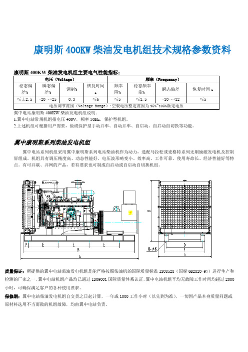
康明斯400KW柴油发电机组技术规格参数资料康明斯400KW柴油发电机组主要电气性能指标:电压(Voltage)频率(Frequency)稳态偏差% 瞬态偏差%调制%恢复时间s频率降%稳态频率带%瞬态偏差恢复时间s≤±2.5 -20~+25 0.3 ≤6 ≤5 ≤1.5 -10~+12 ≤5电压调节范围(Voltage Range):空载电压整定范围为95%~105%额定电压翼中电站康明斯400KW柴油发电机组说明:1.翼中电站常规机组指电压400V,频率50Hz,保护型机组。
2.上述机组可根据用户需要,做成保护型手动并车、自动并车、自启动、自启动自切换等功能。
翼中康明斯系列柴油发电机组翼中电站系列机组采用翼中康明斯系列电站柴油机作为动力,选配马拉松或麦格特系列无刷励磁发电机及控制屏组成。
机组具有调压精度高、动态性能好、电压波形畸变小、效率高、工作可靠、使用寿命长、经济性能好等特点。
有可并联、并网的产品,若有要求也可制成自启动或自启动自切换机组。
质量保证:所提供的翼中电站柴油发电机组是能严格按照柴油机的国际质量标准ISO8528(国标GB2820-97)进行生产和检测的厂家之一,翼中电站机组产品均已通过ISO9001国际质量体系认证,翼中电站机组平均无故障工作时间均超过2000小时,可确保满足客户的各种使用要求。
保修期:翼中电站柴油发电机组自交货之日起计算,一年或1000工作小时(以先到为准),一切因产品本身质量问题或原材料选用不当而致的机组故障,均由翼中电站负责。
康明斯400KW柴油发电机组主要技术数据*以上参数仅供参考,如有更改恕不另行通知。
康明斯发电机技术AGN 030 – 服务和维护说明书
Application Guidance Notes: Technical Information from Cummins Generator Technologies AGN 030 – Service and MaintenanceDESCRIPTIONSuitable service and maintenance are vital to the reliable operation of the alternator and the safety of anyone coming into contact with the alternator. The alternator should be inspected between scheduled maintenance, in line with inspection procedures and schedules provided by the manufacturer to identify any potential failure modes, signs of misuse or excessive wear and tear.An alternator specific Owner’s Manual (also known as Installation, Service and Maintenance Manual) is supplied with every alternator. The manuals are also published on the website. Each manual includes a Section on Service and Maintenance.The service activities are intended to maximise the life of the alternator but shall not vary, extend or change the terms of the manufacturer’s standard warranty or the customer’s obligation in that warranty.Each service interval is a guide only, developed on the basis that the alternator was installed and is operated in accordance with the manufacturer’s guidelines. If the alternator is located and/or operated in adverse or unusual environmental conditions, the service intervals may need to be more frequent. The alternator should be continually monitored between services to identify any potential failure modes, signs of misuse or excessive wear and tear. Recommended Service ScheduleThe recommended service schedule published in the manual shows the recommended service activities in table rows, grouped by alternator subsystem. Columns of the table show the typesof service activity, whether the alternator must be running, and the service levels. Service frequency is given in running hours or interval time, whichever is sooner. A cross (X) in the cells where a row intersects the column shows a service activity type and when it is required. An asterisk (*) shows a service activity done only when necessary.Service level documents referred to in the recommended service schedules can be purchased directly from Cummins Generator Technologies Customer Service Department, by telephone on +44 1780 484732 or by email: **************************************************. STAMFORD AlternatorsThe recommended service schedule for STAMFORD alternators can be found in Section 7 of the manual, with the following breakdown of sub-sections:Recommended Service ScheduleBearingsControlsCooling SystemCouplingRectifier SystemTemperature SensorsWindings.AvK AlternatorsThe recommended service schedule for AvK alternators can be found in Section 10 of the manual, with the following breakdown of sub-sections:Preventive ServicingSafety PrecautionsRecommended Service ScheduleServicing – General StructureVibrationServicing the Bearings and the Lubrication SystemGenerators with Bearing InsulationService WindingsServicing the Generators CoolerRepairs, Dismantling and Reassembly.Importance of Alternator MaintenanceThe maintenance programme is developed to meet the needs of different alternator designs. There are three types of maintenance strategies;∙Reactive maintenanceo Failure or abnormal operation.∙Preventive time based maintenanceo Time based maintenance.o Based on manufacturer’s experience.Predictive / condition based maintenanceo Maintenance based on actual measurements.A regular preventive maintenance schedule will ensure peak performance, maximize alternator life, maximized reliability and minimize breakdowns.INSTALLATION CONSIDERATIONSThe alternator must be installed in an accessible location with easy access to the main terminal box, bearing cap, air filter, louvers (inlet and outlet) and NDE/DE end brackets. The mentioned access points provide easy access to internal alternator components as shown in Figure 1. This will allow the execution of periodic inspections, local maintenance and removal of the alternator for external services.Figure 1: Internal alternator components that require periodic maintenance. Alternators LiftingDifferent alternator designs must be lifted by hooks or shackles attached to the lifting points (lugs or eyes). Chains of sufficient length, and a spreader bar if necessary must be used when lifting the alternators so as not to damage the terminal box, alternator parts and prevent the rotor from failing out on 1 bearing alternators as shown in Figure 2. When lifting entire Generating Set, the installation engineer must use specially designed Generating Set lifting points, and not alternator lifting lugs.Figure 2: Showing an example of the right and wrong alternator lifting methods. Mechanical CouplingInstallation engineers should follow the alternator manufacturer’s integration instructions provided in the Owner’s Manual. When coupling, the engineer should not attempt to rotate the alternator rotor by levering against the vanes of the cooling fan as shown in Figure 3 as the fan is not designed to withstand such forces and will be damaged. The holes of the coupling discs should be aligned with the flywheel holes by cranking the engine. Additional forces should not be put on the bearings while assembling the coupling half as it will damage the bearings.Figure 3: Alternator cooling fan vanes.SafetyIt is important to follow the alternator manufacturer’s general and local health and safety instructions. Incorrect installation, service or replacement of parts can result in severe equipment damage and personal injury. Only qualified individuals should perform electrical and mechanical component installations. Safety information signs are provided on the equipment to indicate hazards and emphasize instructions.Figure 4: Examples of the safety signs provided on an alternator. Environmental ConditionsAlternators installed in Generating Sets that are sited in arduous ambient environmental conditions may be susceptible to breakdown at their location site, if appropriate service and maintenance is not carried out. Ensuring reliable satisfactory service though, starts with careful consideration being given to the design of the ventilation systems that will be shared by both alternator and engine. Simplifying the considerations to just deciding to have a relatively simple canopy with large openings for the benefit of the engine and then considering the alternator satisfied by the fitting of low cost air filters will result in operating problems.Decisions at the Generating Set design stage about the Canopy design and airflow control must include discussions with the alternator manufacturer to ensure that the appropriate optional extra air-filter / louver kit is nominated or the IP rating of the alternator is increased and that a bespoke maintenance regime is implemented for the complete Generating Set.Refer to AGN072 – Environmental Conditions, for guidance on appropriate installation from the alternator manufacturer’s viewpoint.Alternators in Coastal LocationsFor example; an RTG Crane application is a quite unique situation. For reasons of making the alternator output characteristics suitable to power the Crane’s drive motor, combined with the duty cycle of the variable crane motor load, the alternator is usually operating with quite low winding temperatures. Whilst this low temperature situation would normally be considered to be beneficial, it does introduce a problem when the operating environment is a salt laden with a high humidity. The accepted winding temperature at which moisture is driven from the windings is some 95o C and experience is showing that RTG applications do not achieve this. So we have a winding contaminated by a salt laden atmosphere, combined with the dust and pollutants around a working dockside, plus RIC engined port vehicles adding exhaust by-products to this winding contamination problem. Add to this the humidity and moisture associated with local weather conditions, forming surface moisture on the alternator’s outhang, a winding that is not getting hot enough to drive the moisture off and we have created a winding insulation system with much reduced ‘barrier’ capabilities.The above considers the contaminants that weaken the winding insulation system. The following explains the additional electrical stresses associated with the Variable Speed Drive units used to power the various crane movements.These VSD’s are Non Linear Loads [NLL], with quite high levels of harmonic distortion. The resulting harmonic voltage distortion results in transient voltage conditions that may well be twice the peak value that the alternator would experience under normal linear load conditions.These high transient voltage spikes stress the electrical insulation system, with which a clean uncontaminated winding insulation system can cope. But a contaminated winding will find such transient voltage spikes difficult to contain, followed inevitable by the breakdown of the insulation barrier and winding short circuit.The decision to have the new alternator fitted with IP44 inlet louvers will ensure that whilst the alternator is running, the inlet cooling air is being filtered and moisture droplets are being removed by the Premaberg filter system.However the IP44 filter assembly is not really addressing all the problems of the location being in a coastal, salt laden atmosphere. The problem with salt is that it will form a moisture absorbing film of contamination on the alternator’s winding. When the alternator is working and the windings are hot, the moisture is driven off the windings surface and the insulation resistance - IR - will be high enough to ensure that no insulation breakdown or surface tracking occurs. However; as soon as the Generating Set is stopped, the alternator’s local environment becomes extremely humid, it is at this point the hygroscopic layer of salt that has formed on the windings will absorb moisture and this will result in the windings IR value being reduced to a low level and so, an inability to insulate/isolate phase to phase and phase to earth. Therefore, when the Generating Set is next started and the alternator excites to the normal working voltage - electrical pressure - there is a real risk that an insulation failure will occur as a result of insulation breakdown initiated by surface tracking.The ideal solution is to filter the salt from Generating Set cooling air. But the practicalities must include control of the humidity level of the alternator’s environment and this involves far more than the fitting of an alternator anti-condensation heater.The most successful schemes involve a fan heater bl owing several kW’s of hot air around the Generating Set ‘chamber’ to keep the humidity RH% as low as possible. Obviously, this needs an electrical power supply when the Generating Set is not running and so may well not be an easy option.There may be a way of running-on the Generating Set after its programmed service duty. This would be in a way devised to keep hot dry air circulating whilst the whole Generating Set area temperature is gradually reduced to stop the sudden increase in RH% that occurs around Generating S ets when they are stopped and left trapped in their ‘sweat box’ canopies.It could be that Generating Set’s are operating in parallel, or a Generating Set is operating in parallel with a mains supply. This then suggests an option to introduce some Generating Set environment control, because it would seem that there is always an electrical supply available. We cannot rule out that the stresses associated with miss-paralleling, or the instability of the local mains supply e.g.; micro-interruptions, will damage insulation systems and promote failures. But if the site history is one of winding failures occurring at the point/moment of starting the Generating Set ready to put the unit back into service then, from experience, we would consider saline contamination is the prime culprit.MAINTENANCE OF THE WINDING INSULATION SYSTEMThe only way to check on the condition of the winding insulation system, is by introducing a regular procedure to check the stator winding Insulation Resistance (IR) value and although not normal practice for a low voltage scheme, the Polarisation Index [PI] should be measured too, if the alternator is installed in any challenging environment. This check of IR and PI need only be carried out to the stator winding. The spinning of the rotor and the fact that it operates at low voltages means that it is not, as much, at risk.Refer to AGN015 – Testing Winding Insulation Systems for details of IR and PI testing.At the first sign that the IR and PI are low, the alternator stator winding must be cleaned.T he exciter field is another ‘at risk’ component and the fact that it operates with dc. means that it has a high risk factor due to its operation with fixed polarisation. If the exciter field insulation fails it will also take out the AVR.Cleaning windingsIf cleaning of the windings becomes necessary, then the preferred method is to completely strip the alternator to enable a thorough inspection and then a washing process, which will result in dirt removal by encouraging a washing-out of dirt by an action that will not result in the dirt being forced further into the winding assembly. The washing medium should be clean hot water applied from a directional nozzle at a pressure not exceeding 3bar.At no point should the winding insulation be subjected to a jet of water pressure that is deforming the insulation materials.For extremely oily contaminants, an alternative method is to use a hot pressure wash - not exceeding 3bar – with an added solvent based biodegradable cleaner of neutral pH. Note: ‘Autosmart’ and Aquawash’ are trade names of such biodegradable cleaners.Water-based Alkaline Detergents should not be used for cleaning as they contain ‘wetting agents’ that leave contaminants - in the form of salts - on the winding surfaces. These contaminants are hygroscopic and therefore readily absorb moisture, which will lower the insulation resistance and promote surface tracking.Caution: Inappropriate or badly executed cleaning methods will leave contamination embedded in the winding crevices and this local contamination will promote degradation of the insulation system.After the cleaning process, the windings must be slowly[over several hours] heated to at least 100degC in a thorough drying out procedure of perhaps twelve to twenty four hours. The insulation resistance [IR], phase to phase, and phase to earth, must be measured during this process.Refer to the alternator’s Owner’s Manual (Installation, Service & Maintenance Manual) for the drying out procedures and the IR test procedure, including the values, in Mega-Ohms, that thewinding must achieve before the winding IR can be said to be high enough for the wound assembly to be considered a serviceable unit.Once the windings have been cleaned and the insulation resistance improved to what is considered to be a satisfactory level, the clean and dry windings should be treated with an appropriate ‘over-coating’ electrical anti-tracking resin / varnish. This treatment will offer protection from further immediate in-service recontamination of the winding surface. The chosen anti-tracking material should be of the same insulation thermal rating as the alternator’s insulation system - Class ‘F’ or Class ‘H’.Checks must also be made to ensure that the electrical anti-tracking resin / varnish will adhere to the windings original impregnation materials.Application Guidance Notes are for information purposes only. Cummins Generator Technologies reserves the right to change the contents of Application Guidance Notes without notice and shall not be held responsible for any subsequent claims in relation to the content.。
康明斯发电机组 QSK78系列柴油发动机说明书
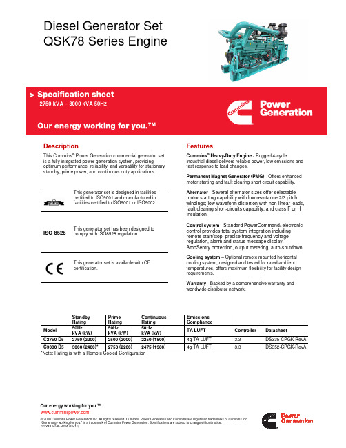
Continuous Rating 50Hz kVA (kW)
2250 (1800)
C3000 D5 3000 (2400)* 2750 (2200) 2475 (1980)
*Note: Rating is with a Remote Cooled Configuration
Emissions Compliance TA LUFT
Fuel Filter
Air Cleaner Type Lube Oil Filter Type(s) Cooling System
Alternator Specifications
Design Stator Rotor Insulation System Standard Temperature Rise Exciter Type Phase Rotation Alternator Cooling AC Waveform Total Harmonic Distortion Telephone Influence Factor (TIF) Telephone Harmonic Factor (THF)
• 240 V control anti-condensation
• Temperature sensor - RTDs,
• Temperature sensor – alternator bearing RTD Exhaust System
• Differential current transformers
Warranty • 2 years warranty • 5 years warranty • 10 year major component warranty
Our energy working for you.™
康明斯发电机操作说明书(维护手册)

康明斯电力系统服务手册柴油发电机组(DF系列/PCC并联控制系统)中文版公告号:EA-MS-5700(英文版公告号:900-0519 7-97)目录章节名称页次安全守则 (iii)1 序言关于本手册....................................................................................................1-1测试设备........................................................................................................1-1如何得到服务.................................................................................................1-1系统概述........................................................................................................1-2发电机组控制功能..........................................................................................1-22 控制操作概述...............................................................................................................2-1安全考虑........................................................................................................2-1操作顺序........................................................................................................2-2PCC接电/备用模式.......................................................................................2-2前端面板........................................................................................................2-4功能显示和按键.............................................................................................2-6主功能...........................................................................................................2-6发动机功能....................................................................................................2-8发电机功能..................................................................................................2-103 电路板和模块概述...............................................................................................................3-1数字电路板(A32).......................................................................................3-3发动机界面电路板(A31)............................................................................3-4模拟电路板(A33).......................................................................................3-6数字显示电路板(A35)................................................................................3-7用户界面电路板(A34)................................................................................3-8电压/电流互感器(PT/CT)电路板(A36).................................................3-10母排电压互感器电路板(A39)...................................................................3-11发电机组通信模块(A39)..........................................................................3-12调压器输出模块(A37)..............................................................................3-17调速器输出模块(A38)..............................................................................3-18最快达标侦测传感器....................................................................................3-194 故障排除概述...............................................................................................................4-1安全考虑........................................................................................................4-1状态指示灯....................................................................................................4-2控制系统复位.................................................................................................4-2报警和报警停机代码......................................................................................4-3PCC机油压力报警和报警停机设定..............................................................4-13故障排除步骤...............................................................................................4-14PCC保险丝.................................................................................................4-54负载分配控制故障排除步骤..........................................................................4-55ⅰ5 控制盘维修及其标定概述..............................................................................................................5-1电路板拆卸/更换............................................................................................5-1初次起动功能设定.........................................................................................5-4调整功能.......................................................................................................5-6设定和标定功能.............................................................................................5-8标定程序.....................................................................................................5-24附件箱控制部件...........................................................................................5-27发动机传感器..............................................................................................5-40发动机转速传感器(MPU)安装.................................................................5-44电流互感器(CT)安装...............................................................................5-45 6 发电机维修发电机测试....................................................................................................6-1绝缘阻抗和极化指数测试...............................................................................6-2绕组干燥步骤................................................................................................6-4发电机/PCC控制盘隔离型母排设定..............................................................6-4励磁机定子....................................................................................................6-5励磁机整流电路板(旋转整流器总成)..........................................................6-6励磁机转子....................................................................................................6-7主转子(发电机磁场)..................................................................................6-8主定子...........................................................................................................6-9测试永久励磁发电机(PMG)......................................................................6-11发电机分解..................................................................................................6-12发电机重新装配...........................................................................................6-21 7 日用油箱燃油输送泵及其控制器操作..............................................................................................................7-2导线连接.......................................................................................................7-4燃油输送泵马达连接......................................................................................7-6测试浮子开关总成.........................................................................................7-78 系统初次起动概述..............................................................................................................8-1起动步骤.......................................................................................................8-1设备应用审查................................................................................................8-2各发电机组起动.............................................................................................8-2系统手动操作................................................................................................8-4系统自动操作................................................................................................8-7黑起动(Black Start)测试............................................................................8-8测试报告和验收.............................................................................................8-8现场电力系统应用审查(柴油机/600 VAC及以下)..........................................................................8-9 9 电路图概述..............................................................................................................9-1ⅱ安全守则操作发电机组之前,需先认真阅读操作手册,以熟悉你的设备,只有正确地操作和维护设备,才能保证安全、有效地运行,许多事故发生的原因是没有遵循基本规则和安全守则造成的。
康明斯船用发电机组技术规格
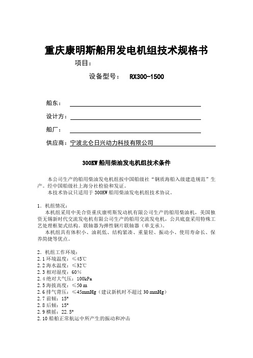
重庆康明斯船用发电机组技术规格书项目:设备型号:RX300-1500船东:设计方:船厂:供应商:宁波北仑日兴动力科技有限公司300KW船用柴油发电机组技术条件本公司生产的船用柴油发电机组按中国船级社“钢质海船入级建造规范”生产。
经中国船级社上海分社检验和发证。
本技术协议只适用于300KW船用柴油发电机组技术协议。
1.机组情况:本机组采用中美合资重庆康明斯发动机有限公司生产的船用柴油机,美国独资无锡新时代交流发电机有限公司生产的船用交流发电机,公共底盘采用特殊工艺处理框架式结构。
联轴器为弹性钢片联轴器(单支承)。
本机组具有体积小、油耗低、结构紧凑、重量轻、振动小、使用寿命长、保养简捷等优点。
2.机组工作环境:2.1环境温度:≤45℃2.2海水温度:≤32℃2.3相对湿度:60%2.4绝对大气压:100kPa2.5海拔高度:≤50 m2.6排气背压:≤45mmHg(建议新机时不超过30 mmHg)2.7前倾:15°2.8后倾:15°2.9横摇:22.5°2.10船舶正常航运中所产生的振动和冲击2.11适合凝雾、盐雾、油雾。
3.本机组主要技术规格3.1机组型号:CCFJ300-1500D3KCST3.2额定功率:300KW/375KVA(符合ISO3046标准)功率修正:1)机组可以在环境温度45℃时没有功率修正。
当环境温度超过45℃时每上升11℃功率下降2%。
2)机组可以在海水温度32℃时没有功率修正。
当海水温度超过32℃时每上升2℃功率下降1%。
3.3额定电流:541A3.4额定电压:AC400V3.5功率因数:0.8(滞后)3.6频率:50HZ3.7相数:三相三线制3.8起动方式:DC24V电起动3.9额定转速:1500r.p.m.3.10调速型式:DC24V 康明斯EFC电子调速器3.11机组过载能力:机组每次运行12小时期间允许以额定功率110%负载运行1/2小时。
康明斯系列柴油发电机组操作、保养规程
康明斯系列柴油发电机组操作、保养规程一、柴油发电机组安装机组安装前必须考虑以下几点:1、底座表面的水平如果底座不够水平,那么发电机组在运行过程中就有可能产生位移,一般机座就高出地面150mm,宽出机组两边各150mm。
2、足够的冷却空气供应机房进风口设置应符合下列要求:进风口应宜设在发电机端或发电机两侧;进风口面积应大于柴油机散热水箱面积的2.2倍;进风口面积应大于排风口面积的1.5倍。
3、足够的新鲜空气这主要是讲,排气方向与进气方向,两者方向最好一致,绝不允许在进气口安装排气口。
4、冷却空气的排放和发动机废气的排放排气口最好对准发动机和散热器,在运行中能够将热量及时排出,否则易引起机房温度过高,发动机高温停机。
5、电器的连接起动电瓶与起动机的距离越近越好,减少压降。
6、操作及维修空间机组四周最好有1-2米的空间,宜于日后的机组保养和维修。
二、柴油发电机组的操作1、起动前的准备:①操作者首先要阅读熟悉操作手册;②检查机组各部分是否正常,各附件连接是否可靠,并排除不正常现象;③检查发动机油底壳内的机油油面是否在规定范围内,最高不要超过H线,最低不要低于L线,否则放掉或添加;④检查冷却系统内冷却液是否符合要求,冷却液面加到距水箱口50mm处,如水箱内无冷却液,向水箱内加注冷却液,速度不要太快,让机体内水道里的空气排出;⑤接通燃油管路,排出燃油管路内的空气;⑥测量起动电池电压是否具备起动该柴油机的容量,接线柱是否牢靠;⑦第一次启动时,要求给增压机里加油,方法是去掉进油管往里面加注少许清洁机油;⑧对于停放较久的发动机央启动前要先转动曲轴3-5转;⑨检查空气开关是否在断开位置。
2、发动机的启动做完起动前的准备工作后,就可以起动发动机。
如果起动机在30秒内未将发动机起动,须停2分钟后再进行起动,以免损坏起动机,三次起动未成功须作进一步的检查,直至起动成功,如果发动机是首次起动,或者是更换过机油或滤清器后起动,应在发动机运转几分钟后停止,并等15分钟后待机油流回到机油盘中,再一次检查机油面是否在规定范围内,如正常可以起动发动机运转。
康明斯柴油机KCM-IIG(A)说明书图纸资料
②低油压报警 n>350r/min 后生效。 5. 停车
① 正常停车操作只需要将电源开关拨至“关”的位置即可。 ② 非正常停车只要迅速按下“紧急停车”按钮和开关即可(如果安装此按钮,事
3
CCEC
● 警示: 仪表箱电气测控系统按船规要求为双线制,即所有电气零部件都必须有
二个以上的接线头。不能采用或更换以壳体搭铁作为负极的单接线电 器,例:马达、充电机、燃油阀等! 仪表箱内从主电源开关至各测量控制板之间均设置有过电流保险器,他 们的容量只能保证自己正常工作,所以不允许外加改装的设备从箱中取 24V 电源,否则会造成仪表工作不正常或损坏! 报警外接延伸板仅有下端 28 个端子供用户外接,其他端子是仪表内接或 远程表用的端子,不允许改接线路它用!
注:仪表的测量精度优于 2.5 级(数字表优于 0.5 级)。 2. 控制开关配置
① 电源开关—用于控制仪表箱电源的通断和正常停车。 ② 仪表主/备电源切换开关—当仪表有主/备二组电源接入时,用它进行转换。 ③ 本机/远起动选择开关—选择在机上起动或远端起动柴油机。 ④ 正常运行/越控运行选择开关—在紧急情况下把此开关拨至“越控”位置时,报
调至 50%、DROOP 调至 1-2 格间(3%Ne)。 ⑤ IDLE(怠速)和 RUN(运行)转速调整电位计均是多圈无限位的,注意要边调边
看,否则难以复位。
五、 继电器报警延伸输出接口及控制连接板
此板提供以下输出口供用户选用(参见附图) ① 远程监测仪表接口端子 8 个,用于连接 KCM-IIGR 远程仪表箱。 ② 连接 PC 计算机的 RS485 接口端子 2 个(需配用 RS485/232 转换器接至计算机,通
柴油发电机技术规范
柴油发电机技术规范本页仅作为文档封面,使用时可以删除This document is for reference only-rar21year.March柴油发电机技术规范:附件1 技术规范1. 总则1.1本设备技术规范书适用于安徽淮南煤电基地田集电厂工程的柴油发电机组,它提出了该设备的功能设计、结构、性能、安装和试验等方面的技术要求。
1.2 买方在本技术规范书中提出了最低限度的技术要求,并未规定所有的技术要求和适用的标准,卖方应提供一套满足本技术规范书和所列标准要求的高质量产品及其相应服务。
1.3 卖方如对本技术规范书有偏差(无论多少或微小)都必须清楚地表示在本技术规范书的附件13“差异表”中。
否则买方将认为卖方完全接受和同意本技术规范书的要求。
1.4 本设备技术规范书所使用的标准如遇与卖方所执行的标准不一致时,按较高标准执行。
1.5 本设备技术规范书经买、卖双方确认后作为订货合同的技术附件,与合同正文具有同等法律效力。
1.6 本设备规范书未尽事宜,由买卖双方协商确定。
1.7 卖方所供设备采用KKS编码,卖方提供设备的KKS编码清单。
KKS编码规则由买方提供。
应答:满足要求。
2 工程概况本期工程新建2台600MW汽轮发电机组,2台机组均采用发电机变压器组单元接线,以500kV电压接入系统。
发电机出口不设断路器,发电机与主变压器用离相封闭母线相连接。
应答:满足要求。
3 设计和运行条件3.1 系统概况和相关设备每台机组设置一台柴油发电机作为本单元机组的应急保安电源,与柴油发电机组配套的附属设备应包括控制、保护等设备。
3.2 工程主要原始资料3.2.1气象资料(1) 气温历年平均气温柴油发电机技术规范:附件1 技术规范1. 总则1.1本设备技术规范书适用于安徽淮南煤电基地田集电厂工程的柴油发电机组,它提出了该设备的功能设计、结构、性能、安装和试验等方面的技术要求。
1.2 买方在本技术规范书中提出了最低限度的技术要求,并未规定所有的技术要求和适用的标准,卖方应提供一套满足本技术规范书和所列标准要求的高质量产品及其相应服务。
康明斯柴油发动机技术参数说明书
-;HA?DIBasic technical dataNumber of cylinders.. ... ... ... ... ... ... ... ... ... ... ... ... ... ... ... ... .12 Cylinder arrangement ... ... ... ... ... ... ... ... ... ... ... ... ... ... 60° Vee Cycle. ... ... ... ... ... ... ... ... ... ... ... ..4 stroke, compression ignition Induction system... ... ... ... ... ... ... ... ... ... ... ... ... ...Turbocharged Compression ratio. ... ... ... ... ... ... ... ... ... ... ... ... ..13,6:1 nominal Bore... ... ... ... ... ... ... ... ... ... ... ... ... ... ... ... ... ... ... ... ... 160 mm Stroke ... ... ... ... ... ... ... ... ... ... ... ... ... ... ... ... ... ... ... ... 190 mm Cubic capacity... ... ... ... ... ... ... ... ... ... ... ... ... ... ... ..45.842 litres Direction of rotation... ... ... ... ...Anti-clockwise viewed on flywheel Firing order ... ... ... ... ... ... ...1A,6B,5A,2B,3A,4B,6A,1B,2A,5B.4A,3B Cylinder 1 furthest from flywheelCylinders designated ‘A’ are on the left side of the engine when viewed from the front (opposite end to flywheel)Total weight Electrounit (engine only)4012TAG1A/2A(dry).. ... ... ... ... ... ... ... ... ... ... ... ... ... ... 4400 kg 4012TAG1A/2A(wet) ... ... ... ... ... ... ... ... ... ... ... ... ... ... 4604 kg Overall dimensions ... ... ... ... ... ... ... ... ... ... ... ...Height 2118 mm .. ... ... ... ... ... ... ... ... ... ... ... ... ... ... ... ... ... ... ..Length 2731 mm .. ... ... ... ... ... ... ... ... ... ... ... ... ... ... ... ... ... ... ....Width 1723 mm Moment of inertia.. ... ... ... ... ... ... ... ... ... ... ... .Engine 9.73 kgm2 .. ... ... ... ... ... ... ... ... ... ... ... ... ... ... ... ... ... ..Flywheel 9.57 kgm2 Cyclic irregularity for engine/flywheel (Prime power):4012TAG1A ... 1500 rev/min ... ... ... ... ... ... ... ... ... ... ... ... 1,714 4012TAG2A ... 1500 rev/min ... ... ... ... ... ... ... ... ... ... ... ... 1,669RatingsSteady state speed stability at constant load. ... ... ... ... ...± 0,25% Electrical ratings are based on average alternator efficiency and are for guidance only (0,8 power factor being used). Operating pointEngine speed. ... ... ... ... ... ... ... ... ... ... ... ... ... ... ...1500 rev/min Static injection timing.. ... ... ... ... ... ... ... See engine number plate Cooling water exit temperature.. ... ... ... ... ... ... ... ... ... ... .<98 °C Fuel dataTo conform to BS2869 class A1, A2.PerformanceSound pressure level 1500 rev/min ... ... ... ... ... ... ...106/112 dBA Note:All data based on operation to ISO 3046/1, BS 5514 and DIN 6271 standard reference conditions.Test conditionsAir temperature... ... ... ... ... ... ... ... ... ... ... ... ... ... ... ... ... ...25 °C Barometric pressure... ... ... ... ... ... ... ... ... ... ... ... ... ... ...100 kPa Relative humidity ... ... ... ... ... ... ... ... ... ... ... ... ... ... ... ... (30)Air inlet restriction at maximum power (nominal)... ... ... ... 2,5 kPa Exhaust back pressure (nominal)... ... ... ... ... ... ... ... ... ... 3,0 kPa4000 Series 4012TAG1A 4012TAG2AGeneral installation 4012TAG1ADesignation Units50Hz 1500 rev/min60Hz 1800 rev/min ContinuousBaseloadPrimePowerStandbyMaximumContinuousBaseloadPrimePowerStandbyMaximumGross engine power kWb94211781292---Fan power kWm42---Net engine power kWm90011361250---BMEP gross bar1620,522,5---Combustion air flow m3/min7695105---Exhaust gas temperature max (after turbo)°C435460470---Exhaust gas flow max (after turbo)m3/min257---Boost pressure ratio-2,73,223,53---Mechanical efficiency%899192---Overall thermal efficiency%424342---Friction power and pumping losses kWm120---Mean piston speed m/s9,5---Engine coolant flow (min)l/s17---Typical Genset Electrical Output 0,8 pf 25 °C (100 kPa)kVA108013631500---kWe86410911200---Assumed alternator efficiency%96---Diesel Engine - ElectrounitGeneral installation 4012TAG2ANote:Not to be used for CHP design purposes. (Indicative figures only). Consult Perkins Engines Co. Ltd. Assumes complete combustion.Continuous Baseload rating Power available for continuous full load operation. Prime Power rating is available for unlimited hours per year with a variable load of which the average engine load factor is 80% of the published prime power rating, incorporation of a 10% overload for 1 hour in every 12 hours of operation which is permitted. Standby Power rating is for the supply of emergency power at variable load for the duration of the non-availability of the mains power supply. NO OVERLOAD capacity is available at this rating. Engines must not be allowed to have facilities for parallel operation with the mains supply. This rating should be applied only when reliable mains power is available. Should this not be the case then refer to Prime Power rating. A standby rated engine should be sized for an average load factor of 80% based on published standby rating for 500 operating hours per year. Standby ratings should never be applied except in true emergency power failure conditions.DesignationUnits 50Hz 1500 rev/min60Hz 1800 rev/minContinuous BaseloadPrime Power Standby Maximum Continuous BaseloadPrime Power Standby MaximumGross engine power kWb 103712961422---Fan power kWm 42---Net engine power kWm 99512541380---BMEP gross bar 18,122,624,8---Combustion air flowm 3/min 83,6106110---Exhaust gas temperature max (after turbo)°C 442472483---Exhaust gas flow max (after turbo)m 3/min 285---Boost pressure ratio -2,83,533,84---Mechanical efficiency %889292---Overall thermal efficiency%424241---Friction power and pumping losses kWm 120---Mean piston speed m/s 9,5---Engine coolant flowl/s 17---Typical Genset Electrical Output 0,8 pf 25 °C (100 kPa)kVA 119415051656---kWe 95512041325---Assumed alternator efficiency%96---Energy balanceNote:Not to be used for CHP design purposes. (Indicative figures only). Consult Perkins Engines Co Ltd. Assumes complete combustion. 4012TAG1A4012TAG2A Units1500 rev/min1800 rev/min ContinuousBaseloadPrimePowerStandbyMaximumContinuousBaseloadPrimePowerStandbyMaximumEnergy in fuel kWt223827703117---Energy in power output (gross) kWb94211781292---Energy to cooling fan kWm424242---Energy in power output (net)kWm90011361250---Energy to exhaust kWt680760924---Energy to coolant and oil kWt353434465---Energy to radiation kWt4495100---Energy to charge coolers kWt219303336---Units1500 rev/min1800 rev/min ContinuousBaseloadPrimePowerStandbyMaximumContinuousBaseloadPrimePowerStandbyMaximumEnergy in fuel kWt244430783477---Energy in power output (gross) kWb103712961422---Energy to cooling fan kWm424242---Energy in power output (net)kWm99512541380---Energy to exhaust kWt7508771013---Energy to coolant and oil kWt372464511---Energy to radiation kWt4995108---Energy to charge coolers kWt236346423---Cooling systemRecommended coolant: 50% inhibited ethylene glycol or 50% inhibited propylene glycol and 50% clean fresh water. For combined heat and power systems and where there is no likelihood of ambient temperatures below 10 °C then clean ‘soft’ water may be used, treated with 1% by volume of Perkins inhibitor in the cooling system. The inhibitor is available in bottles under Perkins Part No. 21825 735.Nominal jacket water pressure in crankcase. ... ... ... ... ... .1,7 bar The following is a guide based on ambient air conditions of 52 °C on a Perkins supplied radiator.Total coolant capacity:Electrounit (engine only) ... ... ... ... ... ... ... ... ... ... ... ... ... 73 litres ElectropaK (engine/radiator) . ... ... ... ... ... ... ... ... ... ... ..235 litres Pressure cap setting.. ... ... ... ... ... ... ... ... ... ... ... ... ... ...0,69 bar Fan. ... ... ... ... ... ... ... ... ... ... ... ... ... ... ...Incorporated in radiator Diameter ... ... ... ... ... ... ... ... ... ... ... ... ... ... ... 1524 mm pusher) Ambient cooling clearance (open ElectropaK Prime power) based on air temperature at fan 3 °C above ambient.4012TAG1A4012TAG2ACoolant pump speed andmethod of drive.. ... ... ... ... ... ... ... ... ... ... ... 1,4 x e rev/min gear Maximum static pressure head on pumpabove engine crank centre line.. ... ... ... ... ... ... ... ... ... ... ... ..7 m Maximum external permissible restrictionto coolant pump flow.. ... ... ... ... ... ... ... ... ... ... ... ... ... ... .20 kPa Thermostat operating range... ... ... ... ... ... ... ... ... ... ... ..71-85 °C Shutdown switch setting ... ... ... ... ... ... ... ... ... ... ... 101 °C rising Coolant immersion heater capacity ... ... ... ... ... ... ... ... ..4 kW x 2 *4012TAG2A **4012TAG1A Lubrication systemRecommended lubricating oil to conform with the specification of API CG4 15W/40 .Lubricating oil capacity:Sump maximum.. ... ... ... ... ... ... ... ... ... ... ... ... ... ... ... 159 litres Sump minimum... ... ... ... ... ... ... ... ... ... ... ... ... ... ... ... 136 litres Lubricating oil temperature maximum to bearings.. ... ... ... 105 °C Lubricating oil pressure:at 80 °C temperature to bearing gallery (minimum) ... ... 0,34 MPa 4012TAG1A4012TAG2A*Typical after 250 hoursSump drain plug tapping size.. ... ... ... ... ... ... ... ... ... ... ... ... ..G1 Oil pump speed and method of drive..1,4 x e rev/min, gear driven Oil pump flow 1500 rev/min. ... ... ... ... ... ... ... ... ... ...6,0 litres/sec Shutdown switch setting.. ... ... ... ... ... ... ... ... ... ...1,93 bar falling Normal operating anglesFore and aft. ... ... ... ... ... ... ... ... ... ... ... ... ... ... ... ... ... ... ... ...5°Side tilt ... ... ... ... ... ... ... ... ... ... ... ... ... ... ... ... ... ... ... ... (10)Maximum additional restriction (duct allowance) to cooling airflow (Prime power) and resultant minimum airflowAmbient clearance 50% glycol Duct allowancemm H20Min airflowm3/minrev/min rev/min rev/min 150018001500180015001800 52 °C52 °20-1872-Maximum additional restriction (duct allowance) to cooling airflow (Prime power) and resultant minimum airflowAmbient clearance 50% glycol Duct allowancemm H20Min airflowm3/minrev/min rev/min rev/min 150018001500180015001800 52 °C52 °20-1872-Jacket cooling water data Units1500rev/min1800rev/minCoolant flow 4012TAG1A/2A l/s17,0-Coolant exit temperature (max)°C98-Coolant entry temperature (min)°C70-Coolant entry temperature (max) *°C85-Coolant entry temperature (max)**°C88-Oil consumptionPrime PowerUnits1500rev/min1800rev/min After running-in*g/kWhr0,50-Oil flow rate from pump I/s6,0-Oil consumptionPrime PowerUnits1500rev/min1800rev/min After running-in*g/kWhr0,51-Oil flow rate from pump I/s6,0-Fuel systemRecommended fuel... ..To conform to BS2869 1998 Class A1, A2 Type of injection system ... ... ... ... ... ... ... ... ... ... ..Direct injection Fuel injection pump... ... ... ... ... ... ... ... ... .Combined unit injector Fuel injector... ... ... ... ... ... ... ... ... ... ... ... .Combined unit injector Fuel injector opening pressure.. ... ... ... ... ... ... ... ... ... ... .234 bar Fuel lift pump. ... ... ... ... ... ... ... ... ... ... ... ... ... .Tuthill TCH 1-089 Delivery/hour at 1500 rev/min... ... ... ... ... ... ... ... ... ... .1020 litres Heat retained in fuel to tank . ... ... ... ... ... ... ... ... ... ... ... ..9,5 kW Temperature of fuel at lift pump to be less than ... ... ... ... ... 58 °C Fuel lift pump pressure.. ... ... ... ... ... ... ... ... ... ... ... ... ... ..3,0 bar Fuel lift pump maximum suction head... ... ... ... ... ... ... ... ... 2,5 m Fuel lift pump maximum pressure head (see Installation Manual) Fuel filter spacing.. ... ... ... ... ... ... ... ... ... ... ... ... ... ..10 microns) Governor type... ... ... ... ... ... ... ... ... ... ... ... ... ... ... ... .Electronic Torque at the governor output shaft.. ... ... ... ... ... ... ... 1,631 kgm Static injection timing ... ... ... ... ... ... ... .See engine number plate Tolerance on fuel consumption. ... ... ... ... ... .To ISO 8528-1 1993 4012TAG1A4012TAG2A Induction systemMaximum air intake restriction of engine:Clean filter.. ... ... ... ... ... ... ... ... ... ... ... ... ... ... ... ... 127 mm H20 Dirty filter ... ... ... ... ... ... ... ... ... ... ... ... ... ... ... ... ... 380 mm H20 Air filter type... ... ... ... ... ... ... ... ... ... ... ... ... ...4998-00-00 MF&T Exhaust systemMaximum back pressure for total system.Exhaust outlet flange size.. ... ... ... ... ... ... .2 x 254 mm (table ‘D’) For recommended pipe sizes, refer to the Installation Manual. Electrical systemType... ... ... ... ... ... ... ... ... ... ... ... ... ... ... ... ... ...Insulated return Alternator ... ... ... ... ... ... ... ... ... ... 24 volts with integral regulator Alternator output. ... ... ...40 amps at a stabilised output 28 volts at20 °C ambient Starter motor.. ... ... ... ... ... ... ... ... ... ... ... ... ... ... ... ... .. 24 volts Starter motor power ... ... ... ... ... ... ... ... ... ... ... ... ... ... ...16,4 kW Number of teeth on flywheel... ... ... ... ... ... ... ... ... ... ... ... ... ..156 Number of teeth on starter motor... ... ... ... ... ... ... ... ... ... ... (12)Minimum cranking speed at (0 °C). ... ... ... ... ... ... ... .120 rev/min Pull-in current of each starter motor solenoid... ... ... ... ... ... ... ... ... ... ... ... ... ... ... ... ... ... .30 amps at 24 volts Hold-in current of each starter motor solenoid... ... ... ... ... ... ... ... ... ... ... ... ... ... ... ... ... ... ...9 amps at 24 volts Engine stop solenoid.. ... ... ... ... ... ... ... ... ... ... ... ... ... ...24 volts Pull-in current of stop solenoid... ... ... ... ... ... .60 amps at 24 volts Hold-in current of stop solenoid.. ... ... ... ... ... 1,1 amps at 24 voltsFuel consumption (gross)Designation g/kWh Litres/hr rev/min1500180015001800 At Standby Max power rating203-309-At Prime Power rating199-276-At Continuous Baseload rating197-218-At 75% of Prime Power rating195-203-At 50% of Prime Power rating194-134-At 25% of Prime power rating207-72-Fuel consumption (gross)Designation g/kWh Litres/hr rev/min1500180015001800 At Standby Max power rating206-345-At Prime Power rating201-306-At Continuous Baseload rating197-240-At 75% of Prime Power rating197-225-At 50% of Prime Power rating195-149-At 25% of Prime power rating207-79-Designation Units1500rev/min1800rev/min 4012TAG1A mmH20949-4012TAG2A mmH20612-Engine mountingPosition of centre of gravity (wet engine) forward from rearface of crankcase .. ... ... ... ... ... ... ... ... ... ... ... ... ... ... ...771 mm Engine vertical centre line above crankshaft centre line ... .38 mm Maximum additional load applied to flywheel due to all rotating components ... ... ... ... ... ... ... ... ... ... ... ... ... ... ... ... ... ... .850 kgStarting requirementsNotes:l Battery capacity is defined by the 20 hour rate at 0 °C.lThe oil specification should be for the minimum ambient temperature as the oil will not be warmed by the immersion heater.lBreakaway current is dependent on battery capacity available. Cables should be capable of handling the transient current which may be up to double the steady cranking current.TemperaturerangeRange Down to 0 °C(32 °F)Oil:Starter:Battery:Max breakaway current:Cranking current:Aids:Starter cable size:Maximum length:API CG4 15W/402 x 24V4 x 12 volts x 286 Ah 1600 amps 810 ampsNot necessary 120 mm 26mGA DrawingLoad acceptance (cold)4012TAG1A1500 rev/min4012TAG2A1500 rev/minAbove complies with requirements of Classifications 3 & 4 of ISO 8528-12 and G2 operating limits stated in ISO 8528-5.The above figures were obtained under test conditions as follows:Engine block temperature.. ... ... ... ... ... ..45 °C Alternator efficiency ... ... ... ... ... ... ... ... ... 96%Minimum ambient temperature.. ... ... ... ..10 °C Isochronous GoverningUnder Frequency Roll Off (UFRO) set to 1 Hz below rated frequency Typical alternator inertia. ... ... ... ... ... .50 Kgm 2All tests were conducted using an engine which was installed and serviced to Perkins Engines Company Limited recommendations.Initial load applicationwhen engine reaches rated speed(15 seconds max after engine starts to crank)2nd Load applicationImmediately after engine has recovered to rated speed(5 seconds after initial load application)Prime power%Load kWm/kWe Nett Transient frequency deviation%Frequency recovery time secondsPrime power%Load kWm/kWe Nett Transient frequency deviation%Frequency recovery time seconds63715/686< -10537422/405< -105Initial load applicationwhen engine reaches rated speed(15 seconds max after engine starts to crank)2nd Load applicationImmediately after engine has recovered to rated speed(5 seconds after initial load application)Prime power%Load kWm/kWe Nett Transient frequency deviation%Frequency recovery time secondsPrime power%Load kWm/kWe Nett Transient frequency deviation%Frequency recovery time seconds57715/686< -10543539/518< -105Noise levelsThe figures for total noise levels are typical for an engine running at Prime Power rating in a semi-reverberant environment and measured at a distance of one metre from the periphery of the engine.Octave analysisThe following histograms show an octave band analysis at the position of the maximum noise level.Total noise levelSound pressure level re: -20 x 10-6 paSpeed 1500 rev/min......Ambient noise level 84 dBA.Octave analysis performed at the position of maximum noise.4012TAG1A4012TAG2APOSITION 11500 rev/min 106 - dBA1800 rev/min ------- dBA1500 rev/min 106 - dBA1800 rev/min ------- dBAPOSITION 21500 rev/min 108 - dBA 1800 rev/min ------- dBA 1500 rev/min 108 - dBA 1800 rev/min ------- dBA POSITION 3 1500 rev/min 111 - dBA 1800 rev/min ------- dBA 1500 rev/min 111 - dBA 1800 rev/min ------- dBA POSITION 4 1500 rev/min 111 - dBA 1800 rev/min ------- dBA 1500 rev/min 111 - dBA 1800 rev/min ------- dBA 4012TAG1A 4012TAG2A 4012TAG1A 4012TAG2A 4012TAG1A 4012TAG2A4012TAG1A4012TAG2A POSITION 71500 rev/min 108 - dBA 1800 rev/min ------- dBA 1500 rev/min 108 - dBA 1800 rev/min ------- dBA POSITION 6 1500 rev/min 112 - dBA 1800 rev/min ------- dBA 1500 rev/min 112 - dBA 1800 rev/min ------- dBA POSITION 5 1500 rev/min 112 - dBA 1800 rev/min ------- dBA 1500 rev/min 112 - dBA 1800 rev/min ------- dBA 4012TAG14012TAG24012TAG14012TAG24012TAG1A4012TAG2AFR4012TAG1A4012TAG2AThe information given on technical data sheets are for standard ratings only. For ratings other than shown contact Perkins Engines Company Limited, Stafford.Notes-;HA?DI All information in the document is substantially correct at the time of printing but may be subsequently altered by the company.Distributed by 4000 Series4012TAG1A 4012TAG2A P u bl i c a t i o n N o . T S L 4253, I s s u e 3, J a n u a r y 2003. P r i n t e d i n E n g l a n d . © P e r k i n s E n g i n e s C o m p a n y L i m i t e d .Perkins Engines Company Limited Stafford ST16 3UB United Kingdom Telephone +44 (0)1785 223141Fax +44 (0)1785 。
柴油发电机技术协议书范本
柴油发电机组项目技术协议甲方:乙方:天汽集团美亚汽车制造(以下简称甲方)委托明辉机电(以下简称乙方)提供柴油发电机组及指导安装调试项目。
经双方协商,为明确双方的义务与责任,特制订以下技术协议,此协议作为合同的附件与合同具有同等法律效力。
一、供货及指导安装调试等围本项目包括柴油发电机组设备制造、运输、指导安装、调试工程。
1、设备名称:柴油发电机组2、型号及数量(表一):(1)表一:3、安装调试设备安装尺寸、外形尺寸、颜色、重量及吊装情况,乙方制造、指导施工前,必须经甲方指定,或通过甲方确认,经甲方认可后方可制造、指导施工。
乙方负责设备在项目现场的指导安装、调试和试运行,直至获得技术监督部门的检验合格证书。
二、技术要求及使用性能参数要求1、性能参数汇总(表二)表二:柴油发电机组主要性能参数表注记:柴油发电机组的设计、制造及有关试验和检验方法应该符合国家有关规和标准,还应该保证使用标准应是最新版本。
2、满足的标准及要求设备制造及安装调试除满足招标文件技术要求,还应符合以下要求:1)国家标准及行业标准和规定;2)投标文件中相关承诺;3)答疑文件,补充文件等相关条款。
3、乙方承诺,(1)系统在正常使用条件下正确使用,使用寿命不少于30年。
(2)噪音和排放标准保证市环保验收通过。
(3)质保期为2年或设备正常运行1000小时,质保期易损件包含在。
(4)控制系统带有联网扩展接口,在甲方需要的情况下可以增加相应的功能模块实现联网功能。
三关键部件的选材(表三):表三。
1:柴油发电机组关键零部件一览表备注:以上是柴油发电机组组成的主要零部件。
四、备品、备件、易损件清单报价(表四)表四:备品、备件、易损件清单报价备注:以上备件是一套机组更换一次易损件清单及报价,不随机组一起提供(甲方另外购买除外),价格不含在总价中。
五、随机资料清单(表五)表五:随机资料清单六、制造及安装调试计划(表六)表六:制造及安装调试计划表七、培训(表七)表七:培训计划表八、售后服务承诺我司对产品的售后服务非常重视,“以质量保信誉,凭服务立口碑”是我们一直坚持的宗旨,竭尽所能为客户提供最完善的售后服务是我们努力的目标。
- 1、下载文档前请自行甄别文档内容的完整性,平台不提供额外的编辑、内容补充、找答案等附加服务。
- 2、"仅部分预览"的文档,不可在线预览部分如存在完整性等问题,可反馈申请退款(可完整预览的文档不适用该条件!)。
- 3、如文档侵犯您的权益,请联系客服反馈,我们会尽快为您处理(人工客服工作时间:9:00-18:30)。
康明斯柴油发电机组技术规范书1 技术规范1. 总则1.1本设备技术规范书适用于****期工程2×600MW国产超临界燃煤机组工程的柴油发电机组,它提出了该设备的功能设计、结构、性能、安装和试验等方面的技术要求。
1.2 买方在本技术规范书中提出了最低限度的技术要求,并未规定所有的技术要求和适用的标准,卖方应提供一套满足本技术规范书和所列标准要求的高质量产品及其相应服务。
1.3 卖方如对本技术规范书有偏差(无论多少或微小)都必须清楚地表示在本技术规范书的附件13“差异表”中。
否则买方将认为卖方完全接受和同意本技术规范书的要求。
1.4 本设备技术规范书所使用的标准如遇与卖方所执行的标准不一致时,按较高标准执行。
1.5 本设备技术规范书经买、卖双方确认后作为订货合同的技术附件,与合同正文具有同等法律效力。
1.6 本设备规范书未尽事宜,由买卖双方协商确定。
2 工程概况参见商务部分3 设计和运行条件3.1 系统概况和相关设备每台机组设置一台柴油发电机作为本单元机组的应急保安电源,与柴油发电机组配套的附属设备应包括控制、保护等设备。
3.2 工程主要原始资料3.2.1气象资料气压历年平均大气压力: 1013.3 hpa气温历年平均气温 15.5?极端最高气温 41.2?极端最低气温 -22.2?历年平均最高气温 20.4?历年平均最低气温 11.4?最热月(7月)平均最高气温 32.5?- 1 -最冷月(1月)平均最低气温 6.3?湿度历年平均水汽压 14.9 hpa历年最大水汽压 40.2 hpa历年最小水汽压 0 hpa历年平均相对湿度 72%历年最小相对湿度 2%耐地震能力地面水平加速度: 0.2g。
地面垂直加速度: 0.1g。
正弦共振三周波,安全系数1.67以上。
历年平均大风日数 7.5 d历年平均雷暴日数 26.6 d历年平均降水日数 105.9 d历年平均雾日数 17.3 d历年最大积雪深度 35 cm历年最大冻土深度 13 cm地面平均温度 17.5?地面最高温度 79.8?地面最低温度 -23.6? (9)海拔高度:不超过1000m。
(10)耐地震能力地面水平加速度:0.2g。
地面垂直加速度:0.1g。
正弦共振三周波,安全系数1.67以上。
11)污秽等级:III级。
( 4 技术参数和性能要求4.1设备名称柴油发电机组,要求整机原装进口。
4.2 型式发动机:固定型,封闭冷却,高转速,废气涡轮增压型柴油机发电机: 三相同步发电机4.3 设备参数- 2 -容量: 1200kW(P) 频率: 50Hz e电压: 400V(U) 功率因数: 0.8 e发电机额定工况效率: ?96% 中性点接地方式: 高阻接地电压波动率: ??0.4%频率波动率: ??0.5%恢复时间特性 ?0.5秒排烟温度: 542?柴油发电机组应能保证在100小时内满载1200KW持续运行。
发电机在其出口发生三相短路时持续10秒而不发生绕组,铁芯等附属部件的有害变形。
柴油机在承受1.2倍的超速运行时不发生有害变形。
整套柴油发电机组保证平均无故障间隔期:10000小时柴油发电机组在不更换柴油机主要零件的情况下能正常工作的保质期不少于150000小时,在买方遵守卖方的使用说明书规定的条件下,卖方保证柴油发电机组在设备安装投入运行1年内,如发生设备质量问题由卖方无偿解决处理。
柴油发电机组在运行中稳态和暂态电压频率调整精度保证值符合第4.4.3节的要求。
开机指令发出15秒内加至满载(感性)。
4.4柴油发电机组的功能要求4.4.1 自起动功能柴油发电机组保证在火电厂的全厂停电事故中, 快速自起动带载运行。
在无人值守的情况下, 接起动指令后在10秒内一次自起动成功, 在60秒内实现一个自起动循环(即三次自起动)。
若自起动连续三次失败, 则发出停机信号, 并闭锁自起动回路。
在买方所提供的现场条件下,机组一次自起动成功率不小于99%。
柴油发电机组自起动成功的定义是: 柴油发电机组在额定转速, 发电机在额定电压下稳定运行2,3秒, 并具备首次加载条件。
4.4.2 带负载稳定运行功能柴油发电机组自起动成功后, 保安负荷分两级投入。
柴油发电机组接到起动指令后10秒内发出a)首次加载指令,允许首次加载不小于50%额定容量的负载(感性);在首次加载后的5秒内再次发出加载指令,允许加载至满负载(感性)运行。
b) 柴油发电机组能在功率因数为0.8的额定负载下, 稳定运行12小时中, 允许有1小时1.1倍的过载运行, 并在24小时内, 允许出现上述过载运行两次。
发电机允许20秒的2倍过载运行。
(过载:额定电压下的过电流)c) 柴油发电机组在全电压下直接起动容量不小于100kW的鼠笼式异步电动机。
d) 在负载容量不低于20%时, 允许长期稳定运行。
4.4.3 自动调节功能- 3 -a) 柴油发电机组的空载电压整定范围为95-105%U。
eb) 柴油发电机组在带功率因数为0.8,1.0的负载,负载功率在0,100%内渐变时应能达到:稳态电压调整率: ??0.5%稳态频率调整率: ??2%(固态电子调速器)电压波动率: ??0.15%(负载功率在25-100%内渐变时)频率波动率: ?0.5%(负载功率在0-25%内渐变时)c) 柴油发电机组在空载状态, 突加功率因数?0.4(滞后)、稳定容量为0.2P的三相对称负载或e在已带80%P的稳定负载再突加上述负载时, 发电机的母线电压0.2秒后不低于85%U。
发电机瞬ee态电压调整率,u?-15%~+20%,电压恢复到最后稳定电压的?3%以内所需时间不超过1秒, 瞬态频率调整率?5%(固态电子调速器),频率稳定时间?3秒。
突减额定容量为0.2P的负载时,柴油发e电机组升速不超过额定转速的10%。
d) 柴油发电机组在空载额定电压时,其正弦电压波形畸变率不大于3%, 柴油发电机组在一定的三相对称负载下,在其中任一相加上25%的额定相功率的电阻性负载,应能正常工作。
发电机线电压的最大值(或最小值)与三相线电压平均值相差不超过三相线电压平均值的5%,柴油发电机组各部分温升不超过额定运行工况下的水平。
4.4.4控制功能柴油发电机组属于无人值守电站, 控制系统具有下列功能:a) 保安段母线电压自动连续监测。
b) 自动程序起动, 远方起动, 就地手动起动。
c) 柴油发电机与保安段正常电源同期并网功能。
d) 运行状态的柴油发电机组自动检测、监视、报警、保护。
e) 主电源恢复后远方控制、就地手动、机房紧急手动停机。
f) 蓄电池自动充电,买方提供不小于 W的380VAC供电电源,具有自动内外部切换功能及蓄电池电压监测。
g) 预润滑、润滑油预热, 冷却水预热。
h) 发电机空间加热器自动投入功能。
4.4.5 模拟试验功能柴油发电机组在备用状态时, 模拟保安段母线电压低至25%U或失压状态, 能够按设定时间快e速自起动运行试验,试验中不切换负荷。
但在试验过程中保安段实际电压降低至25%时能够快速切换带负荷。
4.5 柴油发电机组的性能及结构要求4.5.1 运行要求柴油发电机组能在100小时内连续满容量运行。
柴油发电机组能通过运行方式选择开关, 选择柴油发电机组所处状态。
运行方式选择开关有下列四个位置即“自动”、“试验”、“手动”、“零位”。
- 4 -柴油发电机组正常处于准起动状态即“自动”状态。
自起动时间<10秒。
4.5.2 起动要求保证柴油发电机组自起动快速性和成功率, 保证柴油发电机组正常处于热态,采取对柴油发电机组冷却水, 润滑油的预热和预供手段。
柴油发电机组的起动方式为电起动。
电起动方式的电源, 采用全密封免维护阀控铅酸蓄电池(容量 AH), 蓄电池的浮充装置具备在线小电源浮充和快速充电的两种自动充电功能。
蓄电池的容量满足连续起动15次的用电量要求。
4.5.3 电气接线要求4.5.3.1 一次接线a) 柴油发电机组主开关选用进口施耐德MT型开关,设置在柴油机房的就地配电柜上,开关的额定电流应不低于发电机额定电流的1.5倍,主开关选用框架开关,额定电流不小于3000A,短路电流开断能力63kA,型号以设计院提供图纸为准。
b)所有连接线应采用铜质材料、绝缘应按导体连续温升为60K来选择。
电气一次接线参考图见附图。
4.5.3.2 二次接线柴油发电机组的控制起动、保护、测量、信号系统采用直流电压, 断路器控制, 操作及其信号采用机组自身提供的直流24伏电压。
a) 控制除自动控制的要求外,柴油发电机组还有就地控制屏控制和主机组单元控制室远方强制启动/停机控制方式。
电源的正常切换是利用柴油发电机组的馈线断路器和交流事故保安段上的工作电源进线断路器相互联锁实现。
保安段共有3路进线电源,1路工作电源,1路备用电源,1路柴油机电源。
当保安段失电跳闸时,同时发出备用电源合闸信号;当备用电源合闸失败,发出启动柴油机命令,柴油发电机组投入后应按要求时间带负荷满载。
当保安段工作电源恢复时,在柴油发电机组控制屏上自动或手动同期投入保安段的切换,投工作或备用进线断路器。
当脱硫失电时发出启动柴油机命令。
柴油机段接有脱硫馈线开关,当柴油机收到启动命令,启动柴油机,启动成功后,合保安段脱硫馈线,脱硫馈线合后,脱硫程控发出命令合脱硫侧的保安进线开关。
脱硫恢复供电后,由脱硫控制发出停止柴油机命令,柴油机收到命令后,确认DCS也已处于可停柴油机状态;反之亦然,即柴油机确定收到2个停止命令后才可停机,同时送出反馈信号。
柴油发电机组接到由集控室DCS和脱硫程控发出的停机指令后自动停机并解列、退出运行。
同时,闭锁控制屏上手动和自动启动功能,可安全进行设备维护和检修。
工作电源和备用电源可任意选择,在柴油发电机组控制屏上装设选择开关。
当油箱油位低到只能满足柴油发电机满载运行1小时运行时,应自动起动输送油泵进行补油。
- 5 -以上具体控制方式待设计联络会确认。
b) 保护柴油发电机组保护项目有:(1)机组超速保护声光报警,停机关油门(2)润滑油压低声光报警,停机关油门(3)自启动失败声光报警(4)低压闭锁过流保护声光报警,停机关油门(5)发电机过负荷保护声光报警(6)发电机差动保护声光报警,停机关油门(7)冷却水温高声光报警(8)润滑油温高声光报警(9)日用油箱油位低声光报警(10)发电机事故跳闸声光报警(11)逆功率保护声光报警,停机关油门(12) 失磁保护声光报警,停机关油门(13) 过电压保护声光报警,停机关油门(14)冷却水水位低声光报警过电流保护:保护装设在发电机中性点的分相引出线上,动作于发电机出口断路器跳闸并灭磁;保护装置接线为三相三继电器式接线;过电流保护具备速断(主保护)及定时限(后备保护)二种功能。