SSC8631GS1规格书
(整理)KSD301技术标准和规格书.
度升至平衡后开始测试。
精品文档
精品文档
10.2.2 测试时,在KSD系列温度测试仪上设定产品的动作温度下限、动作温度下限、复位温度 上限、复位温度下限、升温速率、降温速率等测试参数,启动测试键,仪器自动按预先设 定的程序运行,在动作温度下限值再低 5℃,开始温度平衡后以小于 1℃/min 的升温速率对 检测炉内的温控器进行加温,要确保测温炉鼓风机工作进行空气搅伴,使温度分布均匀, 测试夹具上的温度传感器尽可能靠近被测产品。测试复位温度时,在炉温降至复位温度上 限值再高 5℃时保温,温度平衡后再以 1℃/min 的降温速率降温。
该系列温控器适用于装在家用和类似用途单相交流额定电压不大于 250V;额定电流不大于 10A;
交流额定电压不大于 125V;额定电流不大于 16A 的温度控制器具.
2 引用标准
VC-01-Kit 规格书说明书
VC-01-Kit规格书V1.0.0VC- -Kit规格书版本V . .版权 ©文件履历表目录1.产品概述 (4)1.1.特性 (5)2.主要参数 (6)2.1.静电要求 (6)2.2.电气特性 (7)2.3.功耗 (7)3.外观尺寸 (8)4.指示灯及按键说明 (9).管脚定义 (10).原理图 (12).产品相关型号 (13)8.固件烧录方式说明 (13)9.产品包装信息 (14)10.联系我们 (14)免责申明和版权公告 (15)注意 (15)1.产品概述VC-01-Kit是针对VC-01模组设计的开发板,该底板与VC-02-Kit共用。
开发板上集成了CH340C串口转USB芯片,提供基础的调试接口及USB升级接口;唤醒灯及冷暖灯的设计,提供了状态指示及控制指示,且方便调试简单的控制功能。
VC-01是深圳市安信可科技有限公司开发的一款低成本纯离线语音识别模组。
该模组使用云知声推出的语音芯片US516P6,在语音识别技术上不断优化和创新算法,离线识别算法与芯片架构深度融合,为客户提供超低成本的离线语音识别方案,可广泛且快速应用于智能家居,各类智能小家电,86盒,玩具,灯具等需要语音操控的产品。
US516P6芯片采用32bit RSIC架构内核,并加入了专门针对信号处理和语音识别所需要的DSP指令集,支持浮点运算的FPU运算单元,以及FFT加速器。
VC-01支持150条本地指令离线识别,支持RTOS轻量级系统,具有丰富的外围接口,以及简单友好的客制化工具。
图1US516P6芯片架构图1.1.特性内核32bit RISC内核,运行频率240MHz支持DSP指令集以及FPU浮点运算单元FFT加速器:最大支持1024点复数FFT/IFFT运算,或者是2048点的实数FFT/IFFT 运算云知声定制化语音算法算子存储内置242KB高速SRAM内置2MB FLASH音频输入输出灵活配置支持 . / . / . V IO支持1路模拟Mic输入,SNR≥94db支持双声道DAC输出支持中英文语音指令供电和时钟支持5V电源输入内置5V转3.3V,3.3V转1.2V LDO为芯片供电RC 12MHz时钟源和PLL锁相环时钟源内置POR(Power on Reset),低电压检测和看门狗外设所有GPIO均可配置为外部中断输入和唤醒源1个全双工UART最高速率3Mbps。
贝尔赛克半导体指纹模组TS1013M产品规格书

贝尔赛克半导体指纹模组TS1013M产品规格书贝尔赛克半导体指纹模组TS1013M系列产品规格书1产品概述贝尔赛克TS1013M系列半导体指纹模组是一种接触式单指纹识别设备,主要由外壳、TS1013半导体指纹传感器、BIOSEC0702指纹处理芯片(含指纹存储器和识别算法)、通讯接口等组成。
贝尔赛克TS1013M半导体指纹模组具有耐磨、耐腐蚀、耐静电等优势,还特别集成BioSec 自行开发的第9代指纹识别算法芯片,该算法在行业内处于领先地位,各项性能指标均优于同类产品。
TS1013M可以内置处理器,并包含FLASH存储器,指纹的处理、存储和比对全部在芯片内部处理完成,处理速度快,开发接口简单,便于行业用户的二次开发,降低产品开发难度,缩短产品研发周期。
同时,集成化芯片也大大减小了指纹模组的体积。
1.1产品特点指纹模组集成图正自行开发的高性能ARM内核指纹处理芯片,集成化高、体积更小、功耗更低。
产品使用自主研发指纹识别算法和芯片,各项性能指标优于同类产品,而且成本更低。
将指纹采集、存储和识别集成在一起,全部由指纹模组自行处理,处理速度快、效果好。
在指纹传感器设计方面,TS1013M采用晶圆塑封技术,产品具备防雾防尘防破坏能力,有效解决了人体静电的影响、提高了产品采像质量、增加了产品耐用性。
晶圆塑封可按用户要求定制颜色。
内置人体感应器件,具有触摸唤醒功能,并可有效识别塑胶手指、硅胶手指、橡胶手指、指模、指套等假手指。
产品结构简单,模组化设计,提高了产品的稳定性和一致性、便于大规模批量生产。
公开接口代码和命令集,指纹识别处理过程完全对上位机透明,可实现组装式二次开发,降低客户开发难度。
自主知识产权技术可为客户提供高效、灵活的二次开发支持,充分满足客户需求且无知识产权纠纷。
1.2产品外观图1.2.1 产品外观1.3产品结构尺寸图1.3.1 产品结构尺寸2技术指标3产品介绍TS1013M系列半导体指纹模组使用TS1013M系列半导体指纹传感器搭载图正TA0702指纹处理芯片,完成指纹的采集、比对以及相关的扩展功能。
高精度电流传感器规格书.pdf
高精度电流传感器规格书RIT 01深圳市航智精密电子有限公司RIT01 剩余电流传感器多点零磁通技术系统应用于现有高精度直流传感器技术之上,激励磁通闭环控制技术、自激磁通门技术及多闭环控制技术相结合,实现了对激励磁通、直流磁通、交流磁通的零磁通闭环控制,并通过构建高频纹波感应通道实现了对高频纹波的检测,从而使传感器在全带宽范围内拥有比较高的增益和测量精度。
产品图片核心技术性能特点◇激励磁通闭环控制技术◇原、副边隔离测量◇自激退磁技术◇出色的线性度和准确度◇多点零磁通技术◇极低的温漂◇多级量程自动切换技术◇极低的零漂◇温控补偿技术◇强抗电磁干扰能力◇宽频带和低响应时间应用领域◇工业控制◇医疗设备◇铁路◇电力、电网◇电测仪器仪表◇新能源电气性能项目符号测试条件最小值标称最大值单位原边额定电流I PN—0 0.1 — A 原边过载电流I P——200% I PN— A 工作电压V C—±14.2 ±15 ±15.8 V 功耗电流I PWR—±30 mA 输出电压V SN0 ±2 —V精度测量项目符号测试条件最小值标称最大值单位精准度X G输入直流,额定量程——0.2 % 线性度εL全范围——0.2 % 零点电压I OT全温度范围——±10 mV 反应时间t r上升至90%I PN—— 2 us 频带宽度(-3dB) F —0 —100 kHz安全特性项目符号测试条件数值单位隔离电压/ 原边与副边之间Vd 50Hz,1min 5 KV瞬态隔离耐压/ 原边与副边之间Vw 50us 10 KV爬电距离/ 原边与外壳之间dCp —11 mm电气间隙距离/ 原边与外壳之间dCi —11 mm 相比漏电起痕指数CTI IEC-60112 275 V一般特性项目符号测试条件最小标称最大单位工作温度范围T A—-40 —+85 ºC存储温度范围T S—-55 —+95 ºC相对湿度RH —20 80 —质量M ——350±10 —g运行状态说明◇正常运行时,绿灯常亮:设备上电后,当设备正常工作时,绿色指示灯常亮,D-Sub9接口的第3脚和第8脚导通。
GS1A-GS1M规格书
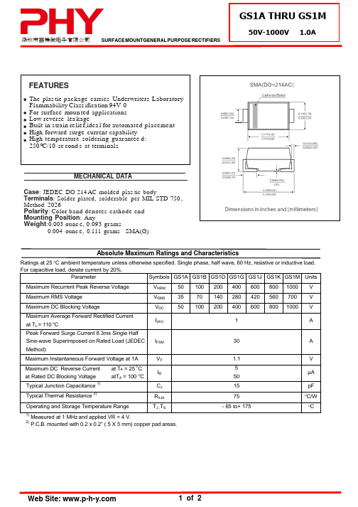
Absolute Maximum Ratings and Characteristics
Ratings at 25 OC ambient temperature unless otherwise specified. Single phase, half wave, 60 Hz, resistive or inductive load. For capacitive load, derate current by 20%. Parameter Symbols GS1A GS1B GS1D GS1G GS1J GS1K GS1M Units Maximum Recurrent Peak Reverse Voltage Maximum RMS Voltage Maximum DC Blocking Voltage Maximum Average Forward Rectified Current at TL = 110 OC Peak Forward Surge Current 8.3ms Single Half Sine-wave Superimposed on Rated Load (JEDEC Method) Maximum Instantaneous Forward Voltage at 1A Maximum DC Reverse Current at Rated DC Blocking Voltage Typical Junction Capacitance Typical Thermal Resistance
FIG. 6-TYP ICAL TRANS IENT THERMAL IMP EDANCE
TRANSIENT THERMAL IMPEDANCE, C/W
200 100 TJ =25 C
SSC-YG101-IC1中文资料
is the off-axis where the luminous intensity is 1/2 the peak intensity.
[Note] All products confirm to the listed minimum and maximum specifications for electric and optical characteristics, when operated at 20mA within the maximum ratings shown above. All measurements were made under the standardized environment of SSC. (Tolerance : Iv ±10 %, λD ±2 nm, VF ±0.1 V)
SEOUL SEMICONDUCTOR CO,. LTD. 148-29 Kasan-Dong, Keumchun-Gu, Seoul, Korea TEL: 82-2-3281-6269 FAX: 82-2-858-5537
SSC-YG101-IC1
- 6/7 -
元器件交易网
SSC-YG101-IC1 Seoul Semiconductor
- 1/7 -
元器件交易网
1. Features
Package : 1.6×0.8×0.8mm Untinted, Diffused flat mold Wavelength : 572㎚
2. Absolute Maximum Ratings Parameter Power Dissipation Forward Current Peak Forward Current Reverse Voltage Operating Temperature Storage Temperature Symbol Pd IF IFM*1 VR Topr Tstg Value 72 30 50 5 -30 ~ 85 -40 ~ 100
优倍G系列仪表 - 产品样本及技术手册(2022)说明书
关于优倍安全栅国家标准主编单位中石化安全栅框架协议单位工信部两化融合贯标单位工信部智能工厂标准化示范验证单位江苏省电涌保护器工程技术研究中心南京优倍电气有限公司成立于2002年,江苏省高新技术企业。
公司致力于安全栅、隔离器、温度变送器、电涌保护器、安全继电器等工业信号接口仪表的研发制造,并为以上产品国标组组长单位,主持起草《隔离式安全栅》等国家标准。
优倍电气是国内该专业市场的主要供应商之一,品牌及品质享受盛誉。
公司为工信部两化融合体系贯标试点单位、工信部智能工厂标准化示范验证单位、江苏省、南京市首批示范智能工厂。
先后被江苏省省委、省政府授予百家江苏省优秀企业、江苏制造突出贡献奖优秀企业、江苏科技小巨人企业等光荣称号。
公司总部及新建并投产运营的优倍智造园均位于南京江宁经济技术开发区,占地面积30亩,全公司现有员工160余名,建有江苏省研究生工作站、江苏省电涌保护器工程技术研究中心、南京市工程应用研究中心,在工业测控领域有着深厚的科研基础及广泛的应用经验,产品获得多项国内、国际认证。
SILIEC 61508目录G系列隔离式安全栅(端子供电)通用型温度变送(常用产品型号)NPEXA-G01 (单通道,1路4 ~ 20mA输出,智能型)NPEXA-G011 (单通道,2路4 ~ 20mA输出,智能型)NPEXA-G0D11 (双通道,2路有源/无源4 ~ 20mA输出,智能型)热电偶输入(常用产品型号)NPEXA-G11 (单通道,1路4 ~ 20mA输出,智能型)NPEXA-G111 (单通道,2路4 ~ 20mA输出,智能型)NPEXA-G1D11 (双通道,2路有源/无源4 ~ 20mA输出,智能型)NPEXA-G11L (单通道,1路4 ~ 20mA输出,回路供电,智能型)热电阻输入(常用产品型号)NPEXA-G21 (单通道,1路4 ~ 20mA输出,智能型)NPEXA-G211 (单通道,2路4 ~ 20mA输出,智能型)NPEXA-G2D11 (双通道,2路有源/无源4 ~ 20mA输出,智能型)NPEXA-G27 (单通道,1路1:1电阻输出,智能型)NPEXA-G277 (单通道,2路1:1电阻输出,智能型)NPEXA-G21L (单通道,1路4 ~ 20mA输出,回路供电,智能型)电流输入(常用产品型号)NPEXA-GM31 (单通道,1路4 ~ 20mA输出,HART通过型)NPEXA-GM311 (单通道,2路4 ~ 20mA输出,HART通过型)NPEXA-GM3D11 (双通道,2路有源/无源4 ~ 20mA输出,HART通过型) NPEXA-G31 (单通道,1路4 ~ 20mA输出,智能型)NPEXA-G311 (单通道,2路4 ~ 20mA输出,智能型)NPEXA-G3D11 (双通道,2路有源/无源4 ~ 20mA输出,智能型)NPEXA-GM31L (单通道,1路4 ~ 20mA输出,回路供电)NPEXA-GM3D11L (双通道,2路4 ~ 20mA输出,回路供电)NPEXA-G31L (单通道,1路4 ~ 20mA输出,回路供电,智能型)模拟量输出(常用产品型号)NPEXB-GM31 (单通道,1路4 ~ 20mA输出,HART通过型)01 01 0203 03 04 0506 06 07 08 08 0910 10 11 12 12 13 14 14 1516INPEXB-GM311 (单通道,2路4 ~ 20mA输出,HART通过型)NPEXB-GM3D11 (双通道,2路4 ~ 20mA输出,HART通过型)NPEXB-GM31L (单通道,1路4 ~ 20mA输出,回路供电)NPEXB-GM3D11L (双通道,2路4 ~ 20mA输出,回路供电)电压信号输入(常用产品型号)NPEXA-G41 (单通道,1路4 ~ 20mA输出,智能型)NPEXA-G411 (单通道,2路4 ~ ~20mA输出,智能型)NPEXA-G4D11 (双通道,2路有源/无源4 ~ 20mA输出,智能型)开关量输入NPEXA-G511 (单通道,1路继电器触点输出)NPEXA-G5111 (单通道,2路继电器触点输出)NPEXA-G5D111 (双通道,2路继电器触点输出)NPEXA-G512 (单通道,1路晶体管输出)NPEXA-G5122 (单通道,2路晶体管输出)NPEXA-G5D122 (双通道,2路晶体管输出)开关量输出NPEXB-G512 (单通道,1路45mA电流输出)NPEXB-G5D12 (双通道,2路45mA电流输出)NPEXB-G512L (单通道,1路45mA电流输出,回路供电)NPEXB-G5D12L (双通道,2路45mA电流输出,回路供电)频率量输入(常用产品型号)NPEXA-G61P2 (单通道,1路4 ~ 20mA输出)NPEXA-G611P2 (单通道,2路4 ~ 20mA输出)NPEXA-G67P2 (单通道,1路1:1频率输出)NPEXA-G677P2 (单通道,2路1:1频率输出)数字通讯输入(常用产品型号)NPEXA-G711Z (单通道,1路RS-485输入,1路RS-485输出,9V/140mA) NPEXA-G711 (单通道,1路RS-485输入,1路RS-485输出,可调配电) NPEXA-G713 (单通道,1路RS-485输入,1路RS-422输出,可调配电) NPEXA-G731 (单通道,1路RS-422输入,1路RS-485输出,可调配电) NPEXA-G733 (单通道,1路RS-422输入,1路RS-422输出,可调配电)16 16 17 1718 18 1920 20 21 22 22 2324 24 25 2526 26 27 2728 29 30 31 32II电位器输入NPEXA-G91 (单通道,1路4 ~ 20mA输出)NPEXA-G911 (单通道,2路4 ~ 20mA输出)G系列模块表(端子供电)温度变送器毫伏中继器电位器变送器模拟量输入隔离器信号智能隔离器开关量输入隔离器频率变送器频率中继器产品附录组态工具33 3334 37 38 40 42 46 47 4849III01*注:电压输出接线参照电流接线 5+、6-, 7+、8-。
TruStability标准精度硅陶瓷(SSC)系列压力传感器说明说明书
DESCRIPTIONThe TruStability ® Standard Accuracy Silicon Ceramic (SSC) Series is a piezoresistive silicon pressure sensor offering a ratiometric analog output for reading pressure over the specified full scale pressure span and temperature range.The SSC Series is fully calibrated and temperaturecompensated for sensor offset, sensitivity, temperature effects, and non-linearity using an on-board Application SpecificIntegrated Circuit (ASIC). Calibrated output values for pressure are updated at approximately 1 kHz.The SSC Series is calibrated over the temperature range of -20 C to 85 C [-4 F to 185 F]. The sensor is characterized for operation from a single power supply of either 3.3 Vdc or 5.0 Vdc.These sensors measure absolute, differential, and gage pressures. The absolute versions have an internal vacuum reference and an output value proportional to absolutepressure. Differential versions allow application of pressure to either side of the sensing diaphragm. Gage versions are referenced to atmospheric pressure and provide an output proportional to pressure variations from atmosphere.The TruStability ®pressure sensors are intended for use with non-corrosive, non-ionic gases, such as air and other dry gases. An available option extends the performance of these sensors to non-corrosive, non-ionic liquids.All products are designed and manufactured according to ISO 9001 standards.FEATURESIndustry-leading long-term stabilityExtremely tight accuracy of 0.25% FSS BFSL (Full ScaleSpan Best Fit Straight Line)Total error band of2% full scale span maximumModular and flexible design offers customers a variety of package styles and options, all with the same industry-leading performance specificationsMiniature 10 mm x 10 mm [0.39 in x 0.39 in] packageLow operating voltageExtremely low power consumptionRatiometric analog outputHigh resolution (min. 0.03 %FSS) Precision ASIC conditioning and temperature compensated over -20 C to 85 C [-4 F to 185F] temperature rangeRoHS compliantVirtually insensitive to mounting orientationInternal diagnostic functions increase system reliabilityAlso available with I 2C or SPI digital outputAbsolute, differential and gage typesPressure ranges from 1 psi to 150 psi (60 mbar to 10 bar)Custom calibration availableVarious pressure port options Liquid media option2 /sensingPOTENTIAL APPLICATIONS Medical:- Airflow monitors- Anesthesia machines - Blood analysis machines - Gas chromatography - Gas flow instrumentation - Kidney dialysis machines - Oxygen concentrators - Pneumatic controls - Respiratory machines - Sleep apnea equipment - VentilatorsIndustrial:- Barometry- Flow calibrators- Gas chromatography - Gas flow instrumentation - HVAC- Life sciences- Pneumatic controls1Honeywell Sensing and Control 3101. Absolute maximum ratings are the extreme limits the device will withstand without damage.2. Ratiometricity of the sensor (the ability of the device to scale to the supply voltage) is achieved within the specified operating voltage for eachoption.3. The sensor is not reverse polarity protected. Incorrect application of supply voltage or ground to the wrong pin may cause electrical failure.4. The compensated temperature range is the temperature range over which the sensor will produce an output proportional to pressure withinthe specified performance limits.5. The operating temperature range is the temperature range over which the sensor will produce an output proportional to pressure but may notremain within the specified performance limits.6. Accuracy: The maximum deviation in output from a Best Fit Straight Line (BFSL) fitted to the output measured over the pressure range at25 °C [77 °F]. Includes all errors due to pressure non-linearity, pressure hysteresis, and non-repeatability.7. Total Error Band: The maximum deviation from the ideal transfer function over the entire compensated temperature and pressure range.Includes all errors due to offset, full scale span, pressure non-linearity, pressure hysteresis, repeatability, thermal effect on offset, thermal effect on span, and thermal hysteresis.8. Full Scale Span (FSS) is the algebraic difference between the output signal measured at the maximum (Pmax.) and minimum (Pmin.) limits ofthe pressure range. (See Figure 1 for ranges.)9. Life may vary depending on specific application in which sensor is utilized. 10. Contact Honeywell Customer Service for detailed material information.CAUTIONPRODUCT DAMAGEEnsure liquid media is applied to Port 1 only; Port 2 is not compatible with liquids.Ensure liquid media contains no particulates. All TruStability ®sensors are dead-ended devices. Particulates can accumulate inside the sensor, causing damage or affecting sensor output.Recommend that the sensor be positioned with Port 1 facing downwards; any particulates in the system are less likely to enter and settle within the pressure sensor if it is in this position.Ensure liquid media does not create a residue when dried; build-up inside the sensor may affect sensor output. Rinsing of a dead-ended sensor is difficult and has limited effectiveness for removing residue.Ensure liquid media are compatible with wetted materials. Non-compatible liquid media will degrade sensor performance and may lead to sensor failure.Failure to comply with these instructions may result in product damage.4 /sensing11. The transfer function limits define the output of the sensor at a given pressure input. By specifying Pmin. and Pmax., the output at Pmin. andPmax., the complete transfer function of the sensor is defined. See Figure 2 for a graphical representation of the transfer function. Other transfer functions are available. Contact Honeywell Customer Service for more information.12. Digital outputs (SPI or I 2C) are also available. Contact Honeywell Customer Service for more information. 13. Custom pressure ranges are available. Contact Honeywell Customer Service for more information. 14. See Table 5 for an explanation of sensor pressure types. 15. See CAUTION on previous page.Honeywell Sensing and Control 5SSCSANN100PGAA3 SIP package, AN pressure port, no diagnostics, 100Output is proportional to the difference between the pressures applied to each port. (Port 1 Port 2)50% point of transfer function set at Port 1 = Port 2.Long-term Stability (1000 hr, 25 C [77 F]) 0.25% FSS 0.25% FSS 0.25% FSS 0.25% FSS 0.25% FSS 0.35% FSS 0.35% FSS 0.25% FSS 0.25% FSS 0.25% FSS 0.35% FSS 0.35% FSS 0.25% FSS 0.25% FSS 0.25% FSS 0.25% FSS 0.25% FSS6 /sensingLong-term Stability (1000 hr, 25 C [77 F]) 0.25% FSS 0.25% FSS 0.25% FSS 0.25% FSS 0.25% FSS 0.25% FSS 0.35% FSS 0.35% FSS 0.35% FSS 0.35% FSS 0.35% FSS 0.25% FSS 0.25% FSS 0.25% FSS 0.25% FSS 0.25% FSS 0.35% FSS 0.35% FSS 0.35% FSS0.35% FSS 0.35% FSS0.35% FSS 0.25% FSS 0.25% FSS 0.25% FSS 0.25% FSS 0.25% FSS 0.25% FSS16. Overpressure: The maximum pressure which may safely be applied to the product for it to remain in specification once pressure is returned tothe operating pressure range. Exposure to higher pressures may cause permanent damage to the product. Unless otherwise specified this applies to all available pressure ports at any temperature with the operating temperature range.17. Burst pressure: The maximum pressure that may be applied to any port of the product without causing escape of pressure media. Productshould not be expected to function after exposure to any pressure beyond the burst pressure.18. Common mode pressure: The maximum pressure that can be applied simultaneously to both ports of a differential pressure sensor withoutcausing changes in specified performance.Honeywell Sensing and Control78 /sensingHoneywell Sensing and Control910 /sensingHoneywell Sensing and Control 11Sensing and Control Honeywell1985 Douglas Drive NorthGolden Valley, MN 55422 008215-2-EN IL50 GLO Printed in USA March 2011© 2011 Honeywell International Inc.WARNINGWARRANTY/REMEDYHoneywell warrants goods of its manufacture as being free of defective materials and faulty workmanship. Honeywell s standard product warranty applies unless agreed to otherwise by Honeywell in writing; please refer to your order acknowledgement or consult your local sales office for specific warranty details. If warranted goods are returned to Honeywell during the period of coverage, Honeywell will repair or replace, at its option, without charge those items it finds defective. The foregoing is buyer s sole remedy and is in lieu of all other warranties, expressed or implied, including those of merchantability and fitness for a particular purpose. In no event shall Honeywell be liable for consequential, special, or indirect damages.While we provide application assistance personally, through our literature and the Honeywell web site, it is up to the customer to determine the suitability of the product in the application.Specifications may change without notice. The information we supply is believed to be accurate and reliable as of this printing. However, we assume no responsibility for its use.WARNINGMISUSE OF DOCUMENTATIONThe information presented in this product sheet is forreference only. DO NOT USE this document as aproduct installation guide.Complete installation, operation, and maintenanceinformation is provided in the instructions supplied witheach product.Failure to comply with these instructions could result in death or serious injury.SALES AND SERVICEHoneywell serves its customers through a worldwide network of sales offices, representatives and distributors. For application assistance, current specifications, pricing or name of the nearest Authorized Distributor, contact your local sales office or:E-mail:*********************Internet: /sensingPhone and Fax:Asia Pacific +65 6355-2828; +65 6445-3033 FaxEurope +44 (0) 1698 481481; +44 (0) 1698 481676 Fax Latin America +1-305-805-8188; +1-305-883-8257 FaxUSA/Canada +1-800-537-6945; +1-815-235-6847+1-815-235-6545 Fax。
深圳市多恩技术有限公司2022产品手册说明书
S H I F T T O S A F E T Y安全/传感/控制2022产品手册Products and ServicesS h e n z h e n T o r e n t T e c h n o l o g y C o.,L t d.深圳市多恩技术有限公司0755********1. 功能安全控制器及传感器,产品最高可达PLe/SiL3安全性能等级,符合中国及全球标准,通过欧美专业机构和中国国家检测中心认证,应用于自动化设备,AGV,物流系统,数控机床,电梯,机器人,风电等诸多行业;2. 提供专业的自动化产线整体安全防护系统风险评估,设计与定制。
一站式交钥匙工程,最高符合PLe/SiL3安全性能等级,快速实现安全智能连接。
多恩技术是专业的安全传感控制研发企业,具备TUV 认证的机械安全风险评估资质,同时也是中国机械工业安全卫生协会会员单位,公司产品具有多项发明及实用新型专利,并获得多家国内国际权威机构认证。
Profile公司简介产品与服务P&S技术与荣誉Honor多恩技术是专注于工业安全控制与传感技术的研发型企业,由曾任职于世界100强工业电气巨头的海归工程师团队创建,具备电子、电气、机械核心研发能力,团队70%以上为十年以上工业行业经验的研发人员。
我们 的目标是让产品功能及应用精益求精,解决工业生产的安全难题,把安全的基因更加广泛植入到国内的传感与控制系统中,推动工业4.0的战略早日实现。
引言CONENT 目录0102040607081012141516171820多功能安全继电器功能型安全继电器可配置安全继电器佰安翼AnEZ 电磁式安全联锁开关截留钥匙型安全开关门栓把手部件安全触边/地毯安全围栏安全控制系统Safety V+可视化监视系统安全评估与改造行业应用引言01切割事故会造成严重的后果,比如人员伤亡,设备受损,生产停滞,经济赔偿,行政处罚,法务支出,额外的事故处理人力及费用,企业名誉受损等。
Ra-01S规格书说明书
Ra-01S规格书版本V1.1版权©2020免责申明和版权公告本文中的信息,包括供参考的URL地址,如有变更,恕不另行通知。
文档“按现状”提供,不负任何担保责任,包括对适销性、适用于特定用途或非侵权性的任何担保,和任何提案、规格或样品在他处提到的任何担保。
本文档不负任何责任,包括使用本文档内信息产生的侵犯任何专利权行为的责任。
本文档在此未以禁止反言或其他方式授予任何知识产权使用许可,不管是明示许可还是暗示许可。
文中所得测试数据均为安信可实验室测试所得,实际结果可能略有差异。
文中提到的所有商标名称、商标和注册商标均属其各自所有者的财产,特此声明。
最终解释权归深圳市安信可科技有限公司所有。
注意由于产品版本升级或其他原因,本手册内容有可能变更。
深圳市安信可科技有限公司保留在没有任何通知或者提示的情况下对本手册的内容进行修改的权利。
本手册仅作为使用指导,深圳市安信可科技有限公司尽全力在本手册中提供准确的信息,但是深圳市安信可科技有限公司并不确保手册内容完全没有错误,本手册中的所有陈述、信息和建议也不构成任何明示或暗示的担保。
文件制定/修订/废止履历表版本日期制定/修订内容制定核准V1.02020.8.12首版徐V1.12020.8.19更新部分参数徐目录一、产品概述 (5)二、电气参数 (6)三、外观尺寸 (8)四、管脚定义 (10)五、原理图 (11)六、设计指导 (12)七、回流焊曲线图 (14)八、包装信息 (15)九、联系我们 (15)一、产品概述安信可LoRa系列模块(Ra-01S)由安信可科技设计开发。
该模组用于超长距离扩频通信,其射频芯片SX1268主要采用LoRa™远程调制解调器,用于超长距离扩频通信,抗干扰性强,能够最大限度降低电流消耗。
借助SEMTECH的LoRa™专利调制技术,SX1268具有超过-148dBm的高灵敏度,+22dBm的功率输出,传输距离远,可靠性高。
同时,相对传统调制技术,LoRa™调制技术在抗阻塞和选择方面也具有明显优势,解决了传统设计方案无法同时兼顾距离、抗干扰和功耗的问题。
- 1、下载文档前请自行甄别文档内容的完整性,平台不提供额外的编辑、内容补充、找答案等附加服务。
- 2、"仅部分预览"的文档,不可在线预览部分如存在完整性等问题,可反馈申请退款(可完整预览的文档不适用该条件!)。
- 3、如文档侵犯您的权益,请联系客服反馈,我们会尽快为您处理(人工客服工作时间:9:00-18:30)。
SSC8631GS1Complementary Enhancement Mode Field Effect Transistorz Features z ApplicationsN-ChannelVDS VGS RDSon TYP ID30V±20V 22mR@-10V7A 35mR@-4V5P-ChannelVDS VGS RDSon TYP ID-30V±20V 27mR@-10V-6.5A39mR@-4V5¾Inverter¾CCFL Driverz Pin configurationTop Viewz General DescriptionSSC8631GS1uses advanced trench technology to provideexcellent R DS(ON)and low gate charge.The complementaryMOSFETs may be used to form a level shifted high sideswitch,and for a host of other applications.z PackageInformationz Absolute Maximum Ratings@T A=25°C unless otherwise notedParameter Symbol N-channel P-channel Unit Drain-Source Voltage V DSS30-30V Gate-Source Voltage V GSS±20±20V Continuous Drain Current(Note1)I D7-6A Plused Drain Current(Note2)I DM30-30A Total Power Dissipation(Note1)P D11W Operating and Storage Junction Temperature Range T J,T STG-55to+150-55to+150°CSSC8631GS1 z N-channel Electrical Characteristics@T A=25°C unless otherwise notedParameter Symbol Test Conditions Min Typ Max Unit Drain–Source Breakdown Voltage V(BR)DSS V GS=0V,I D=250uA30----V Gate Threshold Voltage V GS(TH)V DS=V GS,I D=250uA1 1.53V Gate–Body Leakage Current I GSS V GS=±20V,V DS=0V----±100nA Zero Gate Voltage Drain Current I DSS V DS=24V,V GS=0V----1uADrain–Source On–State Resistance R DS(ON)V GS=10V,I D=5A--2228mR V GS=4.5V,I D=5A--3540Forward Transconductance G FS V DS=5V,I D=5A--7.3--S Diode Forward Voltage V SD V GS=0V,I S=1A--0.76 1.7VInput Capacitance C ISSV DS=15V,V GS=0V,f=1.0MHz --407--pFOutput Capacitance C OSS--113--Reverse Transfer Capacitance C RSS--57--Turn–On Delay Time T D(ON)V DS=15V,R L=2.3R,V GS=10V,R GEN=3R ----18nSTurn–Off Delay Tim T D(OFF)----70z P-channel Electrical Characteristics@T A=25°C unless otherwise notedParameter Symbol Test Conditions Min Typ Max Unit Drain–Source Breakdown Voltage V(BR)DSS V GS=0V,I D=-250uA-30----V Gate Threshold Voltage V GS(TH)V DS=V GS,I D=-250uA-1-1.5-3V Gate–Body Leakage Current I GSS V GS=±20V,V DS=0V----±100nA Zero Gate Voltage Drain Current I DSS V DS=-24V,V GS=0V-----1uADrain–Source On–State Resistance R DS(ON)V GS=-10V,I D=-6A--2735mR V GS=-4.5V,I D=-5A--3950Forward Transconductance G FS V DS=-5V,I D=-4A--12--S Diode Forward Voltage V SD V GS=0V,I S=-1A---0.77-1.7VInput Capacitance C ISSV DS=-15V,V GS=0V,f=1.0MHz --950--pFOutput Capacitance C OSS--137--Reverse Transfer Capacitance C RSS--118--Turn–On Delay Time T D(ON)V DS=-15V,R L=2.5R,V GS=-10V,R GEN=3R ----18nSTurn–Off Delay Tim T D(OFF)----70Notes:1.DUT is mounted on a1in2FR-4board with2oz.Copper in a still air environment at25°C,the current rating is based onthe DC(<10s)test conditions2.Repetitive rating,pulse width limited by junction temperature.V DS , Drain-Source Voltage (V)Figure 1. Output CharacteristicsV GS , Gate-to-source Voltage(V)Figure 2. Transfer Characteristics0100200300400500600700C , C a p a c i t a n c e (p F )V DS , Drain-to-Source Voltage (V)Figure 3. Capacitance R D S (O N ),O n R e s i s t a n c e (m R )Tj, Junction Temperature (oC)Figure 4. On Resistance Vs. Temperature-500501001501.01.21.41.61.82.0Tj, Junction Temperature (oC)Figure 5. Threshold Vs. TemperatureV T H , T h r e s h o l d V o l t a g e (V )0.00.20.40.60.8 1.0 1.20.010.1110I S , S o u r c e D r a i n C u r r e n t (A )Figure 6. Diode Forward CharacteristicsV SD , Body Diode Forward Voltage (V)SSC8631GS1zP-channel Typical Performance Characteristics012345678910I D , D r a i n C u r r e n t (A )Figure 1. Output CharacteristicsV DS , Drain-Source Voltage (V)0.00.51.01.52.02.53.03.54.0012345678910I D , D r a i n c u r r e n t(A )V GS , Gate-to-source Voltage(V)Figure 2. Transfer Characteristics0200400600800100012001400C , C a p a c i t a n c e (p F )V DS , Drain-to-Source Voltage (V)Figure 3. Capacitance5101520253035404550Tj, Junction Temperature (oC)Figure 4. On Resistance Vs. TemperatureR D S (O N ),O n R e s i s t a n c e (m R )-50-252550751001251500.91.01.11.21.31.41.51.6Tj, Junction Temperature (oC)Figure 5. Gate Threshold Vs. TemperatureV T H , T h r e s h o l d V o l t a g e (V )0.40.50.60.70.80.9 1.00.1110I S , S o u r c e D r a i n C u r r e n t (A )Figure 6. Diode Forward CharacteristicsV SD , Body Diode Forward Voltage (V)SSC8631GS1 DISCLAIMERSPIRIT-SEMI RESERVES THE RIGHT TO MAKE CHANGES WITHOUT FURTHER NOTICE TO ANY PRODUCTS HEREIN TO IMPROVE RELIABILITY,FUNCTION OR DESIGN.SPIRIT-SEMI DOES NOT ASSUME ANY LIABILITY ARISING OUT OF THE APPLICATION OR USE OF ANY PRODUCT OR CIRCUIT DESCRIBED HEREIN;NEITHER DOES IT CONVEY ANY LICIENCE UNDER ITS PATENT RIGHTS,NOR THE RIGHTS OF OTHERS.THE GRAPHS PROVIDED IN THIS DOCUMENT ARE STATISTICAL SUMMARIES BASED ON A LIMITED NUMBER OF SAMPLES AND ARE PROVIDED FOR INFORMATIONAL PURPOSE ONLY.THE PERFORMANCE CHARACTERISTICS LISTED IN THEM ARE NOT TESTED OR GUARANTEED.IN SOME GRAPHS,THE DATA PRESENTED MAY BE OUTSIDE THE SPECIFIED OPERATING RANGE(E.G,. OUTSIDE SPECIFIED POWER SUPPLY RANGE)AND THEREFORE OUTSIDE THE WARRANTED RANGE.。