LabVIEW IMAQ模块中文说明书
labviewIMAQ模块介绍

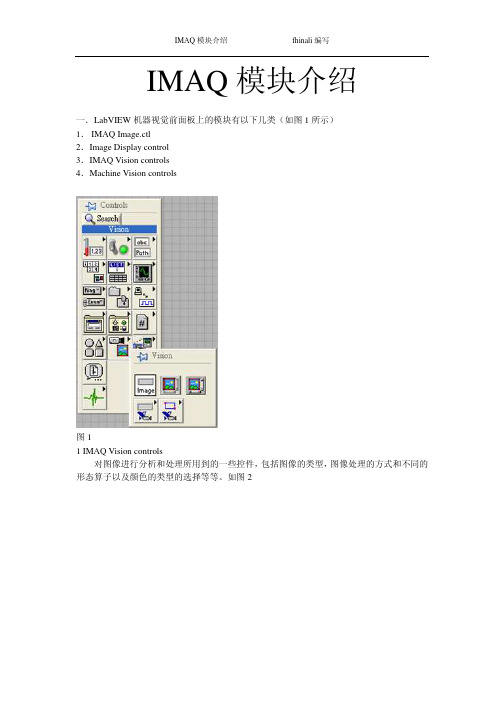
IMAQ模块介绍fhinali编写IMAQ模块介绍一.LabVIEW机器视觉前面板上的模块有以下几类(如图1所示)1.IMAQ Image.ctl2.Image Display control3.IMAQ Vision controls4.Machine Vision controls图11 IMAQ Vision controls对图像进行分析和处理所用到的一些控件,包括图像的类型,图像处理的方式和不同的形态算子以及颜色的类型的选择等等。
如图2IMAQ 模块介绍 fhinali 编写图21.1 Image Type用于图片类型的选择,可以选择的类别有8bits ,16bits ,Float ,Complex ,RGB 和HSL 。
一般用在从文件中读取图片时类型的选择。
1.2 ROI DescriptorROI 区域的描述。
ROI 是Region Of Interesting 的简称,中文应该翻译为目标区域。
一般用在一个大图中取一块特定形状的区域,以便后续的处理和分析。
ROI 为一簇数据,包括一个整数数组和一个簇组成的数组。
整数数组内有4个元素,为图形最小外接矩形的四条边的坐标。
簇数组中的簇由轮廓类型(整数),ROI 类型(整数)和图形坐标点(为数组,根据ROI 类型的不同,数组的定义也不同)1.3Optional Rectangle选择的矩形区域,为四个元素的数组,代表矩形的四条边的坐标。
1.4Color Mode色彩模式,彩色图形的显示和处理模式,包括RGB,HSL,HSV,HIS 四种。
1.5Threshold Range阀值范围,为一包含两个数组元素的簇,常用于灰度或色彩图像阀值处理模块中。
1.6 Convolution Kernel二维浮点数组成的数组,用于构造一些算法的算子。
1.7 Morphology Operation形态算法的选择。
可以选择不同的数据处理方式。
1.8 Structuring Element结构元素,为二维的整数数组。
LabVIEW中文教材

计算机虚拟仪器图形编程LabVIEW实验教材北京中科泛华测控技术有限公司目录第一课LABVIEW概述 (4)第一节虚拟仪器(VI)的概念 (4)第二节L AB VIEW的操作模板 (6)工具模板(Tools Palette) (6)控制模板(Controls Palette) (8)功能模板(Functions Palette) (9)第三节创建一个VI程序 (11)1. 前面板 (11)框图程序 (12)从框图程序窗口创建前面板对象 (14)4. 数据流编程 (14)第四节程序调试技术 (15)1. 找出语法错误 (15)2. 设置执行程序高亮 (15)3. 断点与单步执行 (16)4. 探针 (16)第五节练习1-1 (16)第六节把一个VI程序作为子VI程序调用 (20)第七节练习1-2 (21)第八节练习1-3 (24)第九节练习1-4 (26)第十节练习1-5 (29)第二课数据采集 (33)第一节概述 (33)第二节数据采集VI程序的调用方法 (36)第三节模拟输入与输出 (37)练习2-1 (38)第四节波形的采集与产生 (41)练习2-2 (42)第五节扫描多个模拟输入通道 (43)练习2-3 (44)第六节连续数据采集 (45)练习2-4 (46)第三课仪器控制 (48)第一节概述 (48)第二节串行通讯 (48)第三节IEEE488(GPIB)概述 (50)练习3-1 (52)第四节VISA编程 (53)练习3-2 (55)第五节用L AB VIEW编写仪器驱动程序 (58)第六节验证仪器驱动软件 (58)练习3-3 (60)第四课分析软件 (63)第一节概述 (63)第二节、高级分析功能程序 (63)第三节信号产生 (64)练习4-1 (65)第四节信号处理 (66)练习4-2 (67)第五节数字滤波器 (68)练习4-3 (69)第六节曲线拟合 (71)练习4-4 (72)练习4-5 (74)第五课实用工具软件包 (77)第一节概述 (77)第二节常用软件工具箱 (77)第三节分析工具软件 (80)第一课LabVIEW概述第一节虚拟仪器(VI)的概念使用LabVIEW开发平台编制的程序称为虚拟仪器程序,简称为VI。
labview IMAQ模块介绍
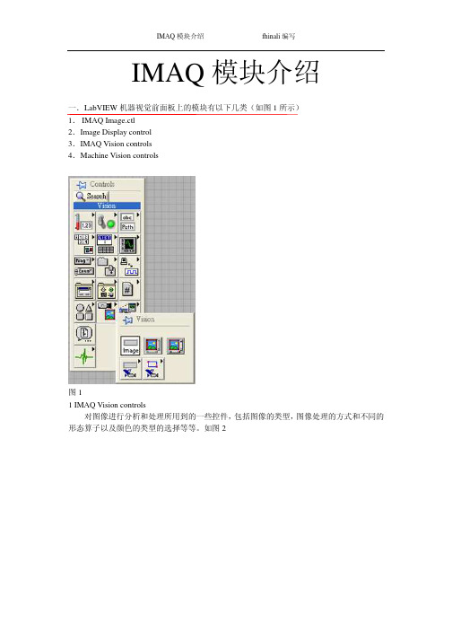
IMAQ模块介绍fhinali编写IMAQ模块介绍一.LabVIEW机器视觉前面板上的模块有以下几类(如图1所示)1.IMAQ Image.ctl2.Image Display control3.IMAQ Vision controls4.Machine Vision controls图11 IMAQ Vision controls对图像进行分析和处理所用到的一些控件,包括图像的类型,图像处理的方式和不同的形态算子以及颜色的类型的选择等等。
如图2IMAQ 模块介绍 fhinali 编写图21.1 Image Type用于图片类型的选择,可以选择的类别有8bits ,16bits ,Float ,Complex ,RGB 和HSL 。
一般用在从文件中读取图片时类型的选择。
1.2 ROI DescriptorROI 区域的描述。
ROI 是Region Of Interesting 的简称,中文应该翻译为目标区域。
一般用在一个大图中取一块特定形状的区域,以便后续的处理和分析。
ROI 为一簇数据,包括一个整数数组和一个簇组成的数组。
整数数组内有4个元素,为图形最小外接矩形的四条边的坐标。
簇数组中的簇由轮廓类型(整数),ROI 类型(整数)和图形坐标点(为数组,根据ROI 类型的不同,数组的定义也不同)1.3Optional Rectangle选择的矩形区域,为四个元素的数组,代表矩形的四条边的坐标。
1.4Color Mode色彩模式,彩色图形的显示和处理模式,包括RGB,HSL,HSV,HIS 四种。
1.5Threshold Range阀值范围,为一包含两个数组元素的簇,常用于灰度或色彩图像阀值处理模块中。
1.6 Convolution Kernel二维浮点数组成的数组,用于构造一些算法的算子。
1.7 Morphology Operation形态算法的选择。
可以选择不同的数据处理方式。
1.8 Structuring Element结构元素,为二维的整数数组。
【免费】LABVIEW-IMAQ模块中文说明书
IMAQ模块介绍一.LabVIEW机器视觉前面板上的模块有以下几类(如图1所示)1.IMAQ Image.ctl2.Image Display control3.IMAQ Vision controls4.Machine Vision controls图11 IMAQ Vision controls对图像进行分析和处理所用到的一些控件,包括图像的类型,图像处理的方式和不同的形态算子以及颜色的类型的选择等等。
如图2图21.1 Image Type用于图片类型的选择,可以选择的类别有8bits ,16bits ,Float ,Complex ,RGB 和HSL 。
一般用在从文件中读取图片时类型的选择。
1.2 ROI DescriptorROI 区域的描述。
ROI 是Region Of Interesting 的简称,中文应该翻译为目标区域。
一般用在一个大图中取一块特定形状的区域,以便后续的处理和分析。
ROI 为一簇数据,包括一个整数数组和一个簇组成的数组。
整数数组内有4个元素,为图形最小外接矩形的四条边的坐标。
簇数组中的簇由轮廓类型(整数),ROI 类型(整数)和图形坐标点(为数组,根据ROI 类型的不同,数组的定义也不同)1.3Optional Rectangle选择的矩形区域,为四个元素的数组,代表矩形的四条边的坐标。
1.4Color Mode色彩模式,彩色图形的显示和处理模式,包括RGB,HSL,HSV,HIS 四种。
1.5Threshold Range阀值范围,为一包含两个数组元素的簇,常用于灰度或色彩图像阀值处理模块中。
1.6 Convolution Kernel二维浮点数组成的数组,用于构造一些算法的算子。
1.7 Morphology Operation形态算法的选择。
可以选择不同的数据处理方式。
1.8 Structuring Element结构元素,为二维的整数数组。
2 Machine Vision controls机器视觉中用到的一些控件,只要是对图像画面进行选择的一些工具,包括点,线和面的选择以及坐标系的设定。
【免费】LABVIEW-IMAQ模块中文说明书

IMAQ模块介绍 fhinali编写IMAQ模块介绍一.LabVIEW机器视觉前面板上的模块有以下几类(如图1所示)1. IMAQ Image.ctl2.Image Display control3.IMAQ Vision controls4.Machine Vision controls图11 IMAQ Vision controls对图像进行分析和处理所用到的一些控件,包括图像的类型,图像处理的方式和不同的形态算子以及颜色的类型的选择等等。
如图2 IMAQ模块介绍 fhinali编写图21.1 Image Type用于图片类型的选择,可以选择的类别有8bits,16bits,Float,Complex,RGB和HSL。
一般用在从文件中读取图片时类型的选择。
1.2 ROI DescriptorROI区域的描述。
ROI是Region Of Interesting的简称,中文应该翻译为目标区域。
一般用在一个大图中取一块特定形状的区域,以便后续的处理和分析。
ROI为一簇数据,包括一个整数数组和一个簇组成的数组。
整数数组内有4个元素,为图形最小外接矩形的四条边的坐标。
簇数组中的簇由轮廓类型(整数),ROI类型(整数)和图形坐标点(为数组,根据ROI类型的不同,数组的定义也不同)1.3Optional Rectangle选择的矩形区域,为四个元素的数组,代表矩形的四条边的坐标。
1.4Color Mode色彩模式,彩色图形的显示和处理模式,包括RGB,HSL,HSV,HIS四种。
1.5Threshold Range阀值范围,为一包含两个数组元素的簇,常用于灰度或色彩图像阀值处理模块中。
1.6 Convolution Kernel二维浮点数组成的数组,用于构造一些算法的算子。
1.7 Morphology Operation形态算法的选择。
可以选择不同的数据处理方式。
1.8 Structuring Element结构元素,为二维的整数数组。
Labview中NI-IMAQdx模块说明
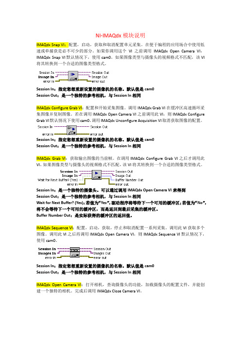
NI-IMAQdx模块说明IMAQdx Snap VI:配置,启动,获取和取消配置单元采集。
在便于编程的应用场合中使用低速或单捕获是必不可少的部分。
如果你调用这个VI之前调用IMAQdx Open Camera VI,IMAQdx Snap VI默认情况下,使用cam0。
如果图像类型与摄像头的视频格式不匹配,该VI 将其转换到一个合适的图像类型格式。
Session In:指定您想重新设置的摄像机的名称。
默认值是cam0Session Out:是一个独特的参考相机,与Session In相同IMAQdx Configure Grab VI:配置和开始采集图像。
调用IMAQdx Grab VI在缓冲区高速循环采集图像并复制图像。
若在调用IMAQdx Open Camera VI之前调用此VI,则IMAQdx Configure Grab VI默认情况下使用cam0。
调用IMAQdx Unconfigure Acquisition VI取消获取图像的配置。
Session In:指定您想重新设置的摄像机的名称。
默认值是cam0Session Out:是一个独特的参考相机,与Session In相同IMAQdx Grab VI:获取输出图像的当前帧。
在调用IMAQdx Configure Grab VI之后才调用此VI。
如果图像类型与摄像头的视频格式不匹配,该VI将其转换到一个合适的图像类型格式。
Session In:是一个独特的摄像头。
可以通过调用IMAQdx Open Camera VI来得到Session Out:是一个独特的参考相机,与Session In相同Wait for Next Buffer? (Yes):若值为“Yes”,驱动程序将等待下一个可用的缓冲区;若值为“No”,将不会等待下一个可用的缓冲区,而是返回到最后采集的缓冲区。
Buffer Number Out:是实际获得的缓冲区的返回值。
labview中文
虚拟仪器(LabVIEW)虚拟仪器是一种高效用于构建数据采集与监测系统图形化编程语言。
使用虚拟仪器,您快速创建用户界面,让您交互控制您的软件系统。
要指定您系统的功能,您只需装配块关系图—一种自然的设计表示科学家和工程师。
测量硬件紧密集成方便了数据采集、分析与演示文稿解决方案的快速发展。
虚拟仪器包含强大的内置度量分析和一个图形的编辑器实现最佳性能。
虚拟仪器是使用于Windows 2000/NT/Me/9x、Mac OS、Linux、Sun Solaris 和HP-UX,有三种不同的开发系统选项。
更快地发展虚拟仪器通过加快发展了对传统的编程提升了4至10倍!使用模块化和层次结构的虚拟仪器,可以原型,设计,并且在一个短时间内修改系统。
您也可以重用虚拟仪器代码轻松快速地在其他应用程序中应用。
更好的投资使用虚拟仪器系统,每个用户有权访问单一的商业文书的成本低于一个完整的检测实验室。
此外,用户还可配置的虚拟仪器系统足够的灵活性,从而更好地长期投资的技术变化与适应。
优化性能虚拟仪器的所有应用程序执行以获得最佳性能的编译速度。
用虚拟仪器专业开发系统或应用程序生成器,可为您的代码的安全通讯生成独立可执行文件或dll。
您甚至可以创建共享的库或从其他编程语言中调用虚拟仪器代码的dll。
开放的开发环境用虚拟仪器在开放开发环境,您可以连接到通过ActiveX、Web、dll、共享的库、SQL(数据库)、DataSocket、TCP/IP和许多其他协议的其他应用程序。
虚拟仪器用于快速创建网络的测量和Web发布和远程数据共享最新的科技集成的自动化系统。
虚拟仪器也可以用于插件数据采集、信号调理、GPIB、VXI、PXI、基于计算机的仪器、串行协议、图像采集和运动控制的驱动程序。
除了在虚拟仪器的开发系统国家仪器还提供多种附加模块和扩展功能的虚拟仪器的工具集。
这使您可以快速构建可定制、鲁棒的测量和自动化系统。
虚拟仪器数据记录和监督控制模块高通道数的分布式应用程序日志记录的虚拟仪器数据和监督控制模块,提供了一个完整的解决方案。
LabVIEW 2013实时模块版本使用说明说明书
RELEASE AND UPGRADE NOTESLabVIEW Real-Time Module Version 2013This document provides system requirements, installation instructions, descriptions of new features, and information about upgrade and compatibility issues for the LabVIEW 2013 Real-Time Module.Refer to the Getting Started with the LabVIEW Real-Time Module manual for exercises you can complete to familiarize yourself with the Real-Time Module.TipRefer to the Real-Time Module Best Practices book in the LabVIEW Help for programming recommendations on designing, developing, and deploying applications with the LabVIEW Real-Time Module. Select Real-Time Module»Real-Time Module Best Practices on the Contents tab of the LabVIEW Help to display this book.ContentsSystem Requirements (2)Installing the LabVIEW 2013 Real-Time Module (2)Activating the Real-Time Module (3)Configuring Real-Time Targets (3)New Features (3)Support for NI Linux Real-Time Targets (3)Enhanced Example VIs (4)Performance Improvements for Advanced Format HDDs on ETS Targets (4)Ethernet Driver MSI Support (4)Networking Improvements on ETS Targets with Multiple Network Cards (4)NI Real-Time Execution Trace Toolkit (4)Activating the NI Real-Time Execution Trace Toolkit (5)Upgrade and Compatibility Issues (5)Known Issues with the Real-Time Module (5)Where to Go from Here (5)Related Documentation and Examples (5)NI Web Site (6)Support (6)™2| |LabVIEW Real-Time Module Release and Upgrade NotesSystem RequirementsThe following section describes the system requirements to run the LabVIEW 2013 Real-Time Module. In addition to the LabVIEW system requirements listed in the LabVIEW Readme , the Real-Time Module has the following requirements:•LabVIEW 2013 Full or Professional Development System (32-bit)•At least 200 MB of disk space in addition to the LabVIEW-recommended minimum.•RT target hardware and driver software.•One of the following operating systems for application development:–Windows 8 (32-bit)–Windows 8 (64-bit with 32-bit LabVIEW installed)–Windows 7 (32-bit)–Windows 7 (64-bit with 32-bit LabVIEW installed)–Windows Server 2003 R2 (32-bit)–Windows Server 2008 R2 (64-bit with 32-bit LabVIEW installed)–Windows Vista (32-bit)–Windows Vista (64-bit with 32-bit LabVIEW installed)–Windows XP Pro (Service Pack 3)NoteYou might need more memory than the LabVIEW-recommended minimum depending on the size of the application you design in LabVIEW on the host computer.Installing the LabVIEW 2013 Real-Time Module Complete the following steps to install LabVIEW and the Real-Time Module on a development computer:1.Log in to the development computer as an administrator or as a user with administrative privileges.2.Insert the LabVIEW 2013 Platform DVD 1.NoteTo request additional LabVIEW 2013 Platform DVDs, refer to the National Instruments website. If you purchased this product with an NI Software Suite or NI Product Bundle, use the installation media that shipped with your purchase to install this product.3.Follow the instructions on the screen to install and activate the following software:•LabVIEW•Real-Time Module•(Optional) PID and Fuzzy Logic Toolkit—Use the Real-Time Module serial number to activate this toolkit.•Device DriversLabVIEW Real-Time Module Release and Upgrade Notes |© National Instruments |3NoteRefer to your hardware-specific documentation for information about installing the appropriate device drivers.Activating the Real-Time ModuleThe Real-Time Module relies on licensing activation. When the evaluation period expires, you must activate a valid Real-Time Module license to continue using the Real-Time Module. You must create an User Profile to activate your software.You can use the NI License Manager, available by selecting Start»All Programs»National Instruments»NI License Manager , to activate National Instruments products. (Windows 8)Click NI Launcher and select NI License Manager in the window that appears. Refer to the National Instruments License Manager Help , available by selecting Help»Contents in the NI License Manager, for information about activating NI products.Configuring Real-Time TargetsUse Measurement & Automation Explorer (MAX) to configure RT targets and to install software and drivers on targets. You can install MAX from the LabVIEW Platform DVD.•Networked RT Targets —Refer to the MAX Remote Systems Help book in theMeasurement & Automation Explorer Help , available by selecting Help»MAX Help from MAX, for information about configuring networked RT targets.•Desktop PC Targets —Refer to the Using Desktop PCs as RT Targets with theLabVIEW Real-Time Module document for information about configuring a desktop PC as a networked RT target. Open the labview\manuals directory and double-click RT_Using_PC_as_RT_Target.pdf to open the document.Note When NI Web-based Configuration & Monitoring is installed on an RTtarget, you can use a web browser to perform common monitoring and configuration tasks on the target. Refer to the Fundamentals»Working with Projects andTargets»How-To»Monitoring and Configuring a Remote Device from a WebBrowser topic on the Contents tab in the LabVIEW Help for information aboutNI Web-based Configuration & Monitoring.New FeaturesThe LabVIEW 2013 Real-Time Module includes the following new features. Refer to the LabVIEW Help, available by selecting Help»LabVIEW Help , for more information about these features.Support for NI Linux Real-Time T argetsThe LabVIEW 2013 Real-Time Module adds support for targets running the NI Linux Real-Time operating system. Refer to the Real-Time Module»Real-Time OperatingSystems»Real-Time Module on NI Linux Real-Time Targets topic on the Contents tab in the LabVIEW Helpfor information about NI Linux Real-Time targets.Enhanced Example VIsUse the NI Example Finder, available by selecting Help»Find Examples from LabVIEW, to find new or enhanced RT examples in the Toolkits and Modules»Real-Time directory. Performance Improvements for Advanced Format HDDs on ETS TargetsThe LabVIEW 2013 Real-Time Module includes performance improvements for Advanced Format HDDs on ETS targets. To take advantage of these improvements, such as increased write speed, you must reformat your hard drive partition.Ethernet Driver MSI SupportThe LabVIEW 2013 Real-Time Module includes support for message signaled interrupt (MSI) on Intel 1000e Ethernet drivers and on Intel 8254 Ethernet drivers for Intel 8257 devices. Networking Improvements on ETS Targets with Multiple Network CardsThe LabVIEW 2013 Real-Time Module adds the following features to ETS targets:•DHCP/AutoIP on secondary network cards•Support for multiple network cards on the same network subnet•Dynamic network reconfiguration based on network card link state•Extended feedback of network device status on target screens and consolesNI Real-Time Execution Trace T oolkitThe LabVIEW Real-Time Module includes a 30-day evaluation of the Real-Time Execution Trace Toolkit. The Real-Time Execution Trace Toolkit includes the Real-Time Execution Trace Tool and the Execution Trace Tool VIs. You can use the Execution Trace Tool VIs to capture the timing and execution data of VI and thread events for applications running on an RT target. The Real-Time Execution Trace Tool displays the timing and event data, or trace session, on the host computer. In LabVIEW, select Tools»Real-Time Module»Execution Trace Toolkit to display the Real-Time Execution Trace Tool.Refer to the Real-Time Execution Trace Toolkit book in the LabVIEW Help for information about using the Real-Time Execution Trace Toolkit to debug real-time applications. Select Help»LabVIEW Help to display the LabVIEW Help. In the LabVIEW Help, browse to Toolkits»Real-Time Execution Trace Toolkit to view the Real-Time Execution Trace Toolkit book.4||LabVIEW Real-Time Module Release and Upgrade NotesActivating the NI Real-Time Execution T race ToolkitThe Real-Time Execution Trace Toolkit relies on licensing activation. You have a temporary license for a 30-day evaluation period. When the evaluation period expires, you must activate a valid Real-Time Execution Trace Toolkit license to continue using the Real-Time Execution Trace Toolkit. You can use the NI License Manager to activate the Real-Time Execution Trace Toolkit.Upgrade and Compatibility IssuesYou might encounter compatibility issues when upgrading to the Labview 2013 Real-Time Module from the LabVIEW 2012 Real-Time Module. Refer to previous versions of the LabVIEW Real-Time Module Release and Upgrade Notes, available on /manuals, for changes in previous versions of the Real-Time Module.NI Linux Real-Time T argetsCertain conventions on ETS and VxWorks targets, such as the file transfer mechanism and directory structure, do not apply on NI Linux Real-Time targets.Refer to the Real-Time Module»Real-Time Operating Systems»Real-Time Module onNI Linux Real-Time Targets topic on the Contents tab in the LabVIEW Help for information about NI Linux Real-Time targets.Known Issues with the Real-Time ModuleRefer to the National Instruments website at /info and enter the Info CodeLVRT2013KIL to access the known issues for the LabVIEW 2013 Real-Time Module. Where to Go from HereNational Instruments provides many resources to help you succeed with your NI products. Use the following resources as you start exploring LabVIEW and the Real-Time Module. Related Documentation and ExamplesUse the following resources to learn more about using LabVIEW and the Real-Time Module:•LabVIEW Help—Available by selecting Help»LabVIEW Help in LabVIEW. Browse the Real-Time Module book in the Contents tab for an overview of the Real-Time Module.•Context Help Window—Available by selecting Help»Show Context Help. Context help provides brief descriptions of VIs, functions, and dialog boxes. Context help for most VIs and functions include a link to the complete reference for a VI or function.LabVIEW Real-Time Module Release and Upgrade Notes|© National Instruments|5•Hardware-Specific Documentation—Some RT targets provide printed documentation as well as content in the LabVIEW Help. Use the hardware documentation for information about using the RT target with LabVIEW and for information about hardwarespecifications.•Examples—Use the NI Example Finder, available by selecting Help»Find Examples from LabVIEW, to browse or search for RT example VIs. You also can access example VIs from the labview\examples\Real-Time Module directory.NI Web SiteRefer to /info and enter the Info Code rtinfo for the latest NI Developer Zone articles, examples, and support information for the Real-Time Module.Refer to /info and enter the Info Code rttrn to access online training for the Real-Time Module.SupportThe National Instruments website is your complete resource for technical support. At/support you have access to everything from troubleshooting and application development self-help resources to email and phone assistance from NI Application Engineers. National Instruments corporate headquarters is located at 11500North Mopac Expressway, Austin, Texas, 78759-3504. National Instruments also has offices located around the world to help address your support needs. For telephone support in the United States, create your service request at /support and follow the calling instructions or dial 5127958248. For telephone support outside the United States, visit the Worldwide Offices section of / niglobal to access the branch office websites, which provide up-to-date contact information, support phone numbers, email addresses, and current events.6||LabVIEW Real-Time Module Release and Upgrade NotesRefer to the NI Trademarks and Logo Guidelines at /trademarks for more information on National Instruments trademarks. Other product and company names mentioned herein are trademarks or trade names of their respective companies. For patents covering National Instruments products/technology, refer to the appropriate location: Help»Patents in your software, the patents.txt file on your media, or the National Instruments Patents Notice at /patents. You can find information about end-user license agreements (EULAs) and third-party legal notices in the readme file for your NI product. Refer to the Export Compliance Information at /legal/export-compliance for the National Instruments global trade compliance policy and how to obtain relevant HTS codes, ECCNs, and other import/export data.© 2000–2013 National Instruments. All rights reserved.371374K-01Jun13。
IMAQ Vision 1400系统设置指南说明书
IMAQ™,LabVIEW™,and NI-IMAQ™are trademarks of National Instruments Corporation.Product and company names mentioned herein are trademarks or trade names of their respective companies.322457B-01©Copyright 1999,2000National Instruments Corp.All rights reserved.November 2000G ETTING S TARTED WITHY OUR IMAQ V ISION 1400S YSTEMThis note describes how to set up the IMAQ Vision 1400system,a complete,general-purpose system for quickly developing PC-based machine vision applications.With the IMAQ Vision 1400system,you can develop low-cost,customizable solutions for pattern matching,alignment,gauging,inspection,and optical character recognition (OCR)applications.The IMAQ Vision 1400system includes development software,anIMAQ PCI-1409image acquisition device,an analog monochrome camera,a lens,and cabling.What You Need to Get StartedTo set up your IMAQ Vision 1400system,you need the following:❑IMAQ PCI-1409and documentation❑National Instruments driver and application software,as follows:–NI-IMAQ version 2.5or higher –LabVIEW 6.0or higher –IMAQ Vision 5.0or higher –IMAQ Vision Builder 1.0or higher –IMAQ Vision OCR 1.0or higher❑RS-170or CCIR analog monochrome camera❑Camera power supply and cable❑Lens❑BNC cableGetting Started with Your IMAQ Vision 1400System Installing Your SoftwareNote Y ou must install the NI-IMAQ driver software before installing the PCI-1409.Install your software in the following order:1.LabVIEW —Consult your LabVIEW release notes for directions to install LabVIEW.2.NI-IMAQ —Follow the directions in the NI-IMAQ forWindows 2000/NT/Me/9x Release Notes to install the NI-IMAQ driver software.Note If you do not have Adobe Acrobat Reader installed on your computer,install it at this time.Y ou will need Acrobat Reader to access much of the IMAQ and LabVIEW documentation.3.IMAQ Vision —Follow the directions in the IMAQ Vision for LabVIEW Release Notes to install IMAQ Vision.4.IMAQ Vision Builder —Follow the directions in the IMAQ Vision Builder Tutorial to install IMAQ Vision Builder.5.IMAQ Vision OCR —Follow the directions in the IMAQ Vision OCR for LabVIEW Release Notes to install IMAQ VisionOCR.©National Instruments Corporation 3Getting Started with Your IMAQ Vision 1400SystemInstalling Your HardwareRefer to Figure 1as you follow these general instructions to install your hardware:1.Install your PCI-1409.Follow the instructions on pages 1and 2of the Getting Started with Your IMAQ System document.For more information on installing your hardware,see the IMAQ PCI/PXI-1409User Manual .2.Assemble the camera and lens.3.Connect the camera to the PCI-1409with the BNC cable.4.Connect the power supply to the camera.5.Connect the power supply cord to the power supply.6.Plug the power supply cord into a power outlet.7.Start your computer.Figure 1.Installing the IMAQ Vision 1400System 1PCI Slot 2IMAQ PCI-14083Computer 4Camera Power Supply 5Power Supply Cord 6RS-170or CCIR Camera 7Lens 8BNC CableWhere to StartFollow these general steps to learn how to acquire your first image andbegin building imaging applications:1.Follow the instructions on pages3and4of the Getting Started withYour IMAQ System document to acquire your first image.plete the activities in Getting Started with LabVIEW if you are anew LabVIEW user.If you are an experienced LabVIEW user,consultthe LabVIEW User Manual to review basic LabVIEW programmingconcepts.3.To learn how to use the NI-IMAQ VIs,consult the NI-IMAQ UserManual and the NI-IMAQ VI Reference online help.Y ou can find theuser manual in portable document format(PDF)in the Start»NationalInstruments»Vision»Documentation folder.Y ou can access the helpfile from the LabVIEW Help menu.4.To learn how to use IMAQ Vision Builder to build prototypes of yourapplication,perform the exercises in the IMAQ Vision BuilderTutorial.5.To run examples for IMAQ Vision,consult the IMAQ Vision onlinehelp files.You can access the online help from the LabVIEW Helpmenu.For additional information on IMAQ Vision,consult the IMAQVision User Manual and the IMAQ Vision Concepts Manual.6.To learn how to use IMAQ Vision OCR,consult the IMAQ Vision OCRfor LabVIEW Release Notes and run the IMAQ Vision OCR onlinehelp,which you can access from the LabVIEW Help menu.。
视觉调试Labview_中文帮助
视觉调试Labview_中⽂帮助NI Vision for LabVIEW基础(⽬录)NI VISION简介 (4)NI Vision控件模板 (4)NI Vision函数模板 (4)如何创建NI Vision应⽤ (8)准备测量图像 (10)建⽴图像系统 (10)校准图像系统 (11)创建图像 (11)采集或读取图像 (15)显⽰图像 (16)加⼊校准信息 (19)分析图像 (19)改善图像 (20)进⾏灰度和彩⾊测量 (25)定义关注区 (25)测量灰度统计数据 (32)测量彩⾊统计数据 (33)进⾏颗粒分析 (38)创建⼆值图像 (38)改善⼆值图像 (39)完成机器视觉任务 (42)检测物体定位 (43)设置搜索区域 (47)查找测量点 (48)将像素坐标转换成现实坐标 (66)进⾏测量 (66)辨别被测部件 (69)检查图像的缺陷 (73)显⽰结果 (74)校准图像 (77)透视和⾮线性畸变校准 (78)Simple Calibration (86)Save Calibration Information (88)Attach Calibration Information (89)在LabVIEW实时模块中使⽤NI Vision (90)Overview (90)Real-Time System Components (90)Software Installation (91)Image Display (92)Determinism in Real-Time Applications (95)Deployment (101)Troubleshooting (101)NI Vision for LabVIEW基础(⼀):NI Vision简介2010-01-2116:57:08标签:LabView机器视觉原创作品,允许转载,转载时请务必以超链接形式标明⽂章原始出处、作者信息和本声明。
- 1、下载文档前请自行甄别文档内容的完整性,平台不提供额外的编辑、内容补充、找答案等附加服务。
- 2、"仅部分预览"的文档,不可在线预览部分如存在完整性等问题,可反馈申请退款(可完整预览的文档不适用该条件!)。
- 3、如文档侵犯您的权益,请联系客服反馈,我们会尽快为您处理(人工客服工作时间:9:00-18:30)。
IMAQ模块介绍一.LabVIEW机器视觉前面板上的模块有以下几类(如图1所示)1.IMAQ Image.ctl2.Image Display control3.IMAQ Vision controls4.Machine Vision controls图11 IMAQ Vision controls对图像进行分析和处理所用到的一些控件,包括图像的类型,图像处理的方式和不同的形态算子以及颜色的类型的选择等等。
如图2图21.1 Image Type用于图片类型的选择,可以选择的类别有8bits ,16bits ,Float ,Complex ,RGB 和HSL 。
一般用在从文件中读取图片时类型的选择。
1.2 ROI DescriptorROI 区域的描述。
ROI 是Region Of Interesting 的简称,中文应该翻译为目标区域。
一般用在一个大图中取一块特定形状的区域,以便后续的处理和分析。
ROI 为一簇数据,包括一个整数数组和一个簇组成的数组。
整数数组内有4个元素,为图形最小外接矩形的四条边的坐标。
簇数组中的簇由轮廓类型(整数),ROI 类型(整数)和图形坐标点(为数组,根据ROI 类型的不同,数组的定义也不同)1.3Optional Rectangle选择的矩形区域,为四个元素的数组,代表矩形的四条边的坐标。
1.4Color Mode色彩模式,彩色图形的显示和处理模式,包括RGB,HSL,HSV,HIS 四种。
1.5Threshold Range阀值范围,为一包含两个数组元素的簇,常用于灰度或色彩图像阀值处理模块中。
1.6 Convolution Kernel二维浮点数组成的数组,用于构造一些算法的算子。
1.7 Morphology Operation形态算法的选择。
可以选择不同的数据处理方式。
1.8 Structuring Element结构元素,为二维的整数数组。
2 Machine Vision controls机器视觉中用到的一些控件,只要是对图像画面进行选择的一些工具,包括点,线和面的选择以及坐标系的设定。
如图3所示2.1 Point点的选择,包括两个元素的簇,分别为横坐标和纵坐标。
2.2 Line线的选择,包括四个元素的簇,分别为起点和终点的横坐标和纵坐标。
2.3 Rectangle面的选择,包括五个元素的簇,分别为对角线两点横坐标和纵坐标,以及矩形选择的角度。
2.4 Circle环形面,包括六个元素的簇,分别为圆心坐标,内外半径的长度以及起始角和终止角。
图3二以上都是程序前面板上所用到的控件,而LabVIEW强大的图像处理功能都是通过其程序面板上的功能节点来实现的。
主要的节点可以分为以下四大类,如图41 Image Acquisition2 Vision Utilities3 Image Processing4 Machine Vision图41 Image Acquisition图像采集功能模块,主要是通过NI的系列图像采集板卡来获得图像。
节点包括任务的建立,设备的初始化以及硬件参数的设定等功能节点。
如图5图52 Vision Utilities视觉应用模块,用来对图像进行一些初步的整体操作。
如图6图62.1 Image Management图像管理模块,包括建立和清除图像任务,获取图像的各类信息,图像的类型转换等功能节点。
如图72.1.1Create 创建一个图像任务2.1.2Dispose 清除图像任务2.1.3Get Image Size获得图像的大小信息2.1.4Set Image Size 设置图像的大小2.1.5Get Image Info 获得图像信息,包括图像的大小,名称,分辨率等2.1.6Copy 拷贝图像2.1.7Image to Image 一个图像映射到另一个图像上2.1.8Get Offset 针对于mask而言。
获得Mask在图像中的偏移量。
2.1.9Set Offset 针对于mask而言。
设定Mask在图像中的偏移量。
2.1.10Cast Image 图像类型的转换。
2.1.11 Is Vision Info Present 判断图像中是否存在图像信息。
图72.2Files图像文件模块,完成对图像文件的读写,以及图像附加信息的读写操作。
图82.2.1Read File读取图像文件2.2.2Write File保存图像文件2.2.3Get File Info获得图像信息,包括图像的类型,分辨率大小2.2.4Write BMP File保存为BMP图像文件2.2.5Write JPEG File保存为JPEG图像文件2.2.5Write PNG File保存为PNG图像文件2.2.5Write TIFF File保存为TIFF图像文件2.2.6Read Image And Vision Info 读取图像及其附加信息。
2.2.7Write Image And Vision Info 保存图像及其附加信息。
2.3External Display图像的外部显示。
具体功能还不太清楚。
如图9所示图92.4Region of InterestROI模块,主要完成ROI和Mask之间的转化,ROI区域的设定以及在不同坐标系下的转换。
10如图图102.4.1ROIToMask2.4.2MaskToROI以上两者Mask和ROI之间的相互转换。
在一些图像的分析模块中,除了要求输入图片外,还要一个Mask,即只对图片中的Mask区域进行分析,这就要求把自己选择的ROI转换为Mask。
2.4.3Group ROIs把多个ROI数组转换为一个ROI区域。
其中转换后的ROI区域包含原ROI 数组的所有区域。
2.4.4Ungroup ROIs为2.4.3Group ROIs的逆运算,即把一个ROI区域转换为ROI数组,数组中的每个ROI都是一个图形轮廓。
2.4.5 TransformROI把ROI区域从一个坐标系转换为另一种坐标系中。
2.4.6 ROI Conversion ROI和各种点、线、面等各类图形之间的转换。
2.5Image Manipulation11图像处理模块。
包括图像的放大和缩小,平移以及旋转。
如图图112.5.1 Resample重新定义图像的大小,使用此模块可以放大或缩小图像。
2.5.2 Expand 通过调整整幅或一部分图片的分辨率,来放大图片。
2.5.3 Extract 通过调整整幅或一部分图片的分辨率,来缩小图片。
2.5.4 Interlace 分别提取一幅图像的奇偶像素,分成两幅图片。
2.5.5 Symmetry 得到一幅图像的对称图像2.5.6 Rotate得到一幅图像的旋转图像2.5.7 Shift 得到一幅图像的平移图像2.5.8 Unwrap 将环形的图片展开成矩形2.5.9 Clipboard To Image将剪贴的数据拷贝到图像2.5.10 Image To Clipboard 将图像拷贝到剪贴板2.5.11 3DView将图像进行三维变换2.6Pixel Manipulation图像像素处理模块。
对图像的像素直接进行操作,包括图像上点,线,面像素值的获取和设定,以及在图像中插入文本。
如图12图122.6.1 Get pixel value获得图像中某一点的像素值,仅限于灰度图像。
2.6.2 GetRowCol获得图像中某一行或者列的像素值,仅限于灰度图像2.6.3 GetPixelLine获得图像中某一条直线的像素值,仅限于灰度图像2.6.4 ImageToArray将图像转化为数组2.6.5 SetPixelValue 设置图像中某一点的像素值。
2.6.6 SetRowCol 设置图像中某一行或者列的像素值2.6.7 SetPixelLine 设置图像中某一条直线上点的像素值2.6.8 ArrayToImage 将数组转化为图像2.6.9 FillImage将图像中的某块区域用像素值填充2.6.10 Draw 在图像中绘制几何图形2.6.11 Draw Text在图像中添加文字2.7Overlay图像覆盖模块。
可以对图像上的某一点,线,面(多边形,矩形和圆)进行覆盖。
此种覆盖为非破坏性的覆盖,即不破坏原有的图像,覆盖信息可以另外和图像一起保存。
如图13图132.7.1 Overlay Points在图像中覆盖一点或是一组点2.7.2 Overlay Line 在图像中覆盖一条线2.7.3 Overlay Multiple Lines 在图像中覆盖多条直线或多边形2.7.4 Overlay Rectangle 在图像中覆盖一矩形2.7.5 Overlay Oval 在图像中覆盖一椭圆2.7.6 Overlay Arc 在图像中覆盖一弧形2.7.7 Overlay Bitmap 在图像中覆盖一位图2.7.8 Overlay Text 在图像中覆盖文字2.7.9 Clear Overlay在图像中清除覆盖2.7.10 Copy Overlay 在图像中拷贝覆盖2.7.11 Overlay ROI 在图像中覆盖ROI区域2.7.12 Merge Overlay 合并图像中的覆盖2.7.13 Read Image And Vision Info读取图像以及图像信息2.7.14 Write Image And Vision Info 写入图像以及图像信息上述读写图像及信息的模块,是将图像中的覆盖信息一块读取/保存的2.8Calibration校准模块。
校准由于相机镜头的光学畸变而或拍摄角度引起图像变化。
也包含像素坐标系和实际坐标系之间的转换节点。
如图14图142.8.1 Learn Calibration Template对校准模块进行学习2.8.2 Set Simple Calibration 对校准的设置2.8.3 Set Calibration Info 设置图像校准的信息2.8.4 Get Calibration Info 获得图像校准中的信息2.8.5 Convert Real World to Pixel 将实际坐标系转化为图像像素坐标系2.8.6 Convert Pixel to Real World 将图像像素坐标系转化为实际坐标系2.8.7 Correct Calibrated Image对图像进行校准2.8.8和2.8.9与2.7.13和2.7.14模块相同。
可以将图像校准信息也写入文件。
2.9Color Utilities颜色应用模块。
彩色图像中色彩的提取,图像中某点,线,面中色彩的设定或获取,以及不同色彩模型中的转换。
如图15图152.9.1 ExtractColorPlanes 从彩色图像中提取各颜色分量的图像2.9.2 ExtractSingleColorPlane 从彩色图像中提取单个颜色图像2.9.3 ReplaceColorPlane 色彩的替代2.9.4 GetColorPixelValue获得彩色像素点的值2.9.5 SetColorPixelValue 设置彩色像素点的值2.9.6 GetColorPixelLine获得图像中某条直线的像素值数组2.9.7 SetColorPixelLine 设置图像中某条直线的像素值2.9.8 ColorImageToArray将彩色图像转化为数组2.9.9 ArrayToColorImage将数组转化为彩色图像2.9.10 RGBToColor 2 将RGB制式的彩色图像转化为其它制式的彩色图像(如HSL, HSV, HSI)2.9.11 ColorToRGB 将其它制式的彩色图像(如HSL, HSV, HSI)转化为RGB制式2.9.12 ColorValueToInteger 将表示颜色的RGB三种分量转化为整数的形式2.9.13 IntegerToColorValue 将整数形式的颜色转化为RGB三种分量的形式3 Image Processing图像处理模块,主要是对灰度和彩色图像的处理。