控制面板使用说明(EN)
Hikvision 数字控制面板用户手册说明书
64 64 8 64 (8 on-board zones, max 8 wired PIRCAM) 32 Installer: 1 Administrator: 1 Operator: 62 Supports (with GPRS/3G/4G module) 4 ISAPI: Supports iVMS-4200 client software and web client Cloud P2P: Supports cloud P2P privacy protocol DC-09: ARC accessible (ADM-CID/SIA-DCS) CSV-IP:Supports CSV-IP ISUP:Supports ISUP 5.0 Web/iVMS-4200/Hik-ProConnect/Keypad Web/iVMS-4200/Hik-ProConnect 64 (Including 2 on-board relay outputs) 12 V, 1 A Optional Optional 802.11b/g/n (2.4GHz) 1 speed-X bus 1 wired on-board sounder output 1 switch to detect removal from mounting 1 switch to detect front cover open 1 RJ45 10M/100M Ethernet interface 12 to 15 VDC
Security Grade 2, Environment Class II, SP4
控制面板说明书
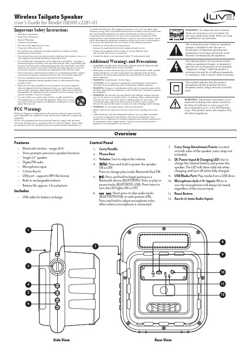
Control Panel1. Carry Handle2. Phone Rest3. Volume: Turn to adjust the volume.4.: Press and hold to power the speaker ON or OFF.Press to change play mode: Bluetooth/Aux/FM.5.: Press and hold to begin pairing to aBluetooth device (BLUETOOTH). Press to play or pause tracks (BLUETOOTH, USB). Press twice to turn the LED lights ON or OFF.6.: Short press to skip audio tracks(BLUETOOTH/USB) or radio presets (FM). Press and hold to adjust microphone echo effect when a microphone is connected.7. Carry Strap Attachment Points: Locatedon both sides of the speaker (carry strap not included).8. DC Power Input & Charging LED: Use tocharge the internal battery and power the speaker. The LED will shine solid red when charging, and turn off when fully charged.9. USB Media Port: Play media from a USB drive.10. Microphone Jack (1/4˝ input): When inuse, the microphones will always be heard, regardless of the source input.11. Reset Button12. Aux In (3.5mm Audio Input)Important Safety Instructions• Read these Instructions.• Keep these Instructions.• Heed all Warnings.• Follow all instructions.• Do not use this apparatus near water.• Clean only with a dry cloth.• Do not block any ventilation openings. Install in accordance with the manufacturer’s instructions.• Do not install near any heat sources such as radiators, heat registers, stoves, or other apparatus (including amplifiers) that produce heat.•Do not defeat the safety purpose of the polarized or grounding - type plug. A polarized plug has two blades with one wider than the other. A grounding type plug has two blades and a third grounding prong. The wide blade or the third prong are provided for your safety. When the provided plug does not fit into your outlet, consult an electrician for replacement of the obsolete outlet.• Protect the power cord from being walked on or pinched particularly at plugs, convenience receptacles, and the point where they exit from the apparatus.• Only use attachments/accessories specified by the manufacturer.• Unplug this apparatus during lightning storms or when unused for long periods of time.•Refer all servicing to qualified service personnel. Servicing is required when the apparatus has been damaged in any way, such as power-supply cord or plug is damaged, liquid has been spilled or objects have fallen into the apparatus, the apparatus has been exposed to rain or moisture, does not operate normally, or has been dropped.•Use only with a cart, stand, tripod, bracket, or table specified by the manufacturer, or sold with the apparatus. When a cart is used, use caution when moving the cart/apparatus combination to avoid injury from tip-over.FCC WarningsWarning: Changes or modifications to this unit not expressly approved by the party responsible for compliance could void the user’s authority to operate the equipment.NOTE: This equipment has been tested and found to comply with the limits for a Class B digital device, pursuant to Part 15 of the FCC Rules. These limits are designed to provide reasonable protection against harmful interference inOverviewWireless Tailgate SpeakerUser’s Guide for Model ISB309 v2281-01a residential installation. This equipment generates, uses, and can radiate radio frequency energy and, if not installed and used in accordance with the instructions, may cause harmful interference to radio communications. However, there is no guarantee that interference will not occur in a particular installation. If this equipment does cause harmful interference to radio or television reception, which can be determined by turning the equipment off and on, the user is encouraged to try to correct the interference by one or more of the following measures:• Reorient or relocate the receiving antenna.• Increase the separation between the equipment and receiver.• Connect the equipment into an outlet on a circuit different from that to which the receiver is connected.• Consult the dealer or an experienced radio/TV technician for help.Additional Warnings and Precautions• CAUTION : TO PREVENT ELECTRIC SHOCK, MATCH WIDE BLADE OF PLUG TO WIDE SLOT, FULLY INSERT.• Mains plug is used as disconnect device and it should remain readily operable during intended use. In order to disconnect the apparatus from the mains completely, the mains plug should be disconnected from the mains socket outlet completely.• WARNING : Shock hazard - Do Not Open.• CAUTION: Use of controls or adjustments or performance of procedures other than those specified may result in hazardous radiation exposure.• WARNING: Changes or modifications to this unit not expressly approved by the party responsible for compliance could void the user’s authority to operate the equipment.• WARNING: Do not place this unit directly onto furniture surfaces with any type of soft, porous, or sensitive finish. As with any rubber compound made with oils, the feet could cause marks or staining where the feet reside. We recommend using a protective barrier such as a cloth or a piece of glassbetween the unit and the surface to reduce the risk of damage and/or staining.• WARNING: Do not ingest battery, chemical burn hazard.• Battery shall not be exposed to excessive heat such as sunshine, fire or the like.• Lithium batteries, like all rechargeable batteries, are recyclable and should be recycled or disposed of according to state and local guidelines. Theyshould never be disposed of in normal household waste and they should never be incinerated, as they might explode. Contact your local government for disposal or recycling practices in your area.WARNING : To reduce the risk of electric shock, do not remove cover (or back). No user-serviceable parts inside. Refer servicing to qualified service personnel.WARNING: This product can expose you to chemicals including lead, which is known to the State of California to cause cancer. For more information go to: This product meets and complies with all Federal regulations.The exclamation point within an equilateral triangle is intended to alert the user to the presence of important operating and maintenance (servicing) instructions in the literature accompanying the appliance.This symbol indicates that this product incorporates double insulation betweenhazardous mains voltage and user accessible parts.The lightning flash with arrowhead symbol, within an equilateral triangle, is intended to alert the user to the presence of un-insulated “dangerous voltage” within the product’s enclosure that may be of sufficient magnitude to constitute a risk of electric shock to persons.Side View Rear ViewFeatures• Bluetooth wireless - range 60 ft.• Voice prompts announce speaker functions • Single 6.5” speaker • Digital FM radio • Microphone input • 3.5mm Aux In• USB port - supports MP3 file format • Built-in rechargeable battery•Battery life: approx. 3 hrs playtimeIncludes•USB cable for battery rechargeMicrophoneRequires a microphone with a 1/4˝ audio cable or 1/4˝ adapter (not included). 1. Connect a microphoneto the Microphone Input on the unit. The speaker will play audio from the microphone as long as it is connected.2. Use the Volume Dialto adjust the overall volume of the speaker and microphone. Pressand hold thebuttons to adjust the echo effect of the microphone.To download this User’s Guide in English, Spanish, or French, or to get answers to frequently asked questions, visit the support section at: Para descargar este Manual del Usuario en inglés, español y francés, o para obtener respuestas a preguntas frecuentes, visite la sección de apoyo en: Pour télécharger ce guide de l’utilisateur en anglais, espagnol ou français, ou pour obtenir des réponses à des questions fréquemment posées, consultez la rubrique d’assistance sur: For Warranty Information and the most up-to-date version of this User’s Guide, go to Customer Service: 1-888-999-4215 | Email Support:*******************|Email Parts:********************Copyright © 2018 Digital Products International (DPI, Inc.) All other trademarks appearing herein are the property of their respective owners. Specifications are subject to change without notice.Customer SupportProtect for T oday Sustain for T omorrowMade GreenAux InRequires a 3.5mm audio cable (not included).1. Connect a 3.5mmaudio cable to the Aux In on the unit and the audio output/headphone jack on an audio device. 2. Press Source to switchto Aux Mode.3. Use the controls on theconnected device to select and play audio. Be sure the volume on your connected device is audible when you begin playing.Bluetooth WirelessPairing & Playing AudioAfter initial pairing, the unit will stay paired unless unpaired manually by the user or erased due to a reset of the device. If your device should become unpaired or you find it is unable to connect, repeat the steps listed here.1. Press thebutton to select Bluetooth Mode, indicated by the voice prompt “Bluetooth”. 2. Press and hold the button to enter pairing mode, indicated by the voiceprompt “Bluetooth is connecting.” The speaker will now be discoverable by your Bluetooth device.3. On your Bluetooth device, scan for and select ISB309 in your Bluetoothsettings to pair. If your device requests a password, enter the default password 0 0 0 0 . Refer to the user’s manual for your specific device for instructions on pairing and connecting Bluetooth devices. 4. When successfully paired, the voice prompt will say “Bluetooth connected.”Use the controls on your connected device to select and begin playing audio. Use the controls on the speaker or the connected device to play, pause, and adjust volume.USB1. Load a USB driveinto the USB Media port. The speaker will automatically switch to USB Mode, indicated by a voice prompt. You can also press the Source button to switch to USB Mode manually.2. Use the controls on thespeaker to select and play audio from the connected drive.FM RadioRadio ReceptionAn FM receiver is built into the speaker. Adjust the position of the speaker to improve FM radio reception.Radio Tuning and Saving Station Presets1. Press the button to select FM Radio Mode, this will be indicated by avoice prompt. 2. Press and hold thebutton to scan and save radio stations automatically.3. Press thebuttons to cycle through saved radio stations. Press and hold to manually search through FM radio frequencies.Charging the BatteryTo power the unit or charge the internal battery, plug the USB charging cable into the DC Power Input on the speaker and a powered on computer or USB power adapter (not included) and standard power outlet. Battery life is approximately3 hours.。
控制面板按键操作及屏显功能说明
一、控制面板按键操作及屏显功能说明:●开关开启及关闭电源,触摸(按)一次进入工作状态,显示屏显示进入待机状态标志,再触摸(按)一次关闭电源。
●功能功能选择键,触摸(按)一次选择一种功能,可按顺序循环选择,当功能选定后,电磁炉便会自动默认工作。
●童锁在选定某一功能进入工作后,触摸(按)“童锁”,电磁炉便会锁定或解除工作状态,关机也会自动解除锁定。
●火锅/煎炒/烧烤按上述键进入相应功能工作状态,按“增大”或“减小”键调节火力,按“定时”键进入时间设定,按“增大”或“减小”键设定时间。
●烧水/泡茶/煮饭/热奶/暖酒/煲汤/煲粥/蒸炖按上述智能键进入相应自动功能工作状态,加热过程自动调节功率。
●保温按此键进入自动保温状态。
●快速加热/火力按上述键进入快速加热状态,按“增大”或“减小”键调节火力,按“定时”键进入时间设定,按“增大”或“减小”键设定时间。
●定时按此键,进入时间设定状态,但在自动功能状态无此作用。
●增大/减小调节定时、火力、温度的大小,但在自动功能状态无此作用。
以上功能键在操作时均点亮相对应的指示灯,并且屏幕显示相应的动态数字。
在每一个加热功能结束蜂鸣器有“DiDi”报警提示音,风扇旋转1-3分钟将机内余热吹散后停止转动。
风扇停止转动后才可拔掉电源。
二、自动功能详叙自动煮饭:首先以适当功率加热至60℃,恒温吸水,加热至水干后,进入焖饭。
自动煲汤:首先以适当功率加热,加热一段时间后,转入小功率慢炖。
自动烧水:以最大功率迅速将水煮开一段时间后,自动关机。
自动热奶:首先以适当功率加热至60-80℃后,维持该温度约30秒进行巴氏灭菌,并自动转入保温,10分钟后自动关机。
三、准备工作1.将电磁炉水平放置,每边与墙或其它物品要留10cm以上间隙。
2.将电源插头插入220V AC/10A以上的专用插座上,电磁炉进行自检,蜂鸣器报警一声,然后进入待机状态。
3.将盛有料理的专用锅具置于电磁炉面板中央。
4.根据需要选择相应的功能进行操作。
控制面板的操作说明

控制面板的操作说明控制面板是计算机、电器或设备的一个重要组成部分,用于控制和管理相关功能和操作。
以下是一些常见设备的控制面板操作说明,帮助用户了解如何使用和操作控制面板。
1.电脑控制面板操作说明:电脑控制面板是一个集中管理和配置计算机硬件和软件的工具,提供了各种选项和设置。
以下是一些常见的控制面板选项和操作说明:-系统:在控制面板的系统选项中,可以查看计算机的基本信息,如操作系统版本、处理器、内存等。
还可以进行一些系统设置,如更改计算机名称、激活操作系统和更改屏幕分辨率等。
-设备管理器:设备管理器是用于管理计算机上的硬件设备的工具。
可以通过设备管理器查看和更新驱动程序、禁用或启用设备,以及查看设备的状态和属性。
常见的设备包括显示器、声卡、网卡、打印机等。
- 网络和 Internet:在控制面板的网络和 Internet 选项中,可以配置和管理计算机的网络连接和 Internet 设置。
可以设置网络适配器、更改 IP 地址和 DNS 设置、启用或禁用网络连接等。
-防火墙:控制面板中的防火墙选项可用于配置计算机的防火墙设置。
可以添加或删除例外规则,允许或拒绝特定的程序或端口进行网络通信。
-用户账户:在用户账户选项中,可以添加、删除或更改计算机上的用户账户。
可以更改用户密码、创建新的用户账户、更改用户权限等。
-外设和打印机:用于管理和配置计算机上的外部设备和打印机。
可以添加或删除打印机、更改默认打印机、配置扫描仪和摄像头等。
2.家用电器控制面板操作说明:家用电器的控制面板通常位于设备的前面板或侧面板,用于控制设备的各种功能和设置。
以下是一些家用电器的控制面板操作说明:-空调控制面板:空调控制面板用于设置温度、风速和模式等。
可以通过控制面板设置制冷或制热模式,调整风速和风向,设置定时开关机等。
-冰箱控制面板:冰箱控制面板用于设置冷冻室和冷藏室的温度,以及冰箱的其他功能。
可以通过控制面板调整温度、打开快速冷冻或快速制冷功能等。
控制面板的操作说明
控制面板的操作说明控制面板是计算机操作系统的一个重要组成部分,用于管理和控制计算机的各种设置和功能。
下面是关于控制面板的详细操作说明:1.打开控制面板在Windows系统中,可以通过以下几种方式打开控制面板:-单击桌面左下角的开始按钮,然后选择“控制面板”。
- 快捷键Win+X,然后选择“控制面板”。
- 在运行框中输入“control”并按回车键。
2.控制面板分类控制面板中的设置按类别进行分组,常见的分类包括:系统和安全、网络和互联网、硬件和声音、程序、用户账户和家庭组。
不同的操作系统会有略微不同的分类方式。
3.系统和安全在“系统和安全”分类下,可以进行各种系统设置和安全选项的配置。
常见的设置包括:系统信息、设备管理器、电源选项、防火墙、自动维护、备份和还原、Windows Defender等。
4.网络和互联网在“网络和互联网”分类下,可以进行各种网络设置和互联网选项的配置。
常见的设置包括:网络和共享中心、Internet选项、设备和打印机、Windows防火墙、添加或删除程序、家庭组等。
5.硬件和声音在“硬件和声音”分类下,可以进行各种硬件设备和音频设置的配置。
常见的设置包括:设备和打印机、显示、音频设备、麦克风配置、键盘、鼠标、麦克风等。
6.程序在“程序”分类下,可以进行各种程序设置和默认程序的配置。
常见的设置包括:卸载程序、默认程序、程序和功能、自动启动程序、Windows更新等。
7.用户账户和家庭组在“用户账户和家庭组”分类下,可以进行用户账户的管理和家庭网络设置的配置。
常见的设置包括:用户账户、家庭网络、家长控制、凭据管理器、管理员工具等。
8.控制面板中的常用设置-更改桌面壁纸:在控制面板中找到“个性化”选项,选择“桌面背景”,然后选择所需的壁纸。
-更改屏幕分辨率:在控制面板中找到“显示”选项,选择“调整分辨率”,然后选择合适的分辨率。
-添加或删除打印机:在控制面板中找到“设备和打印机”选项,选择“添加打印机”或“删除打印机”。
控制面板的操作说明
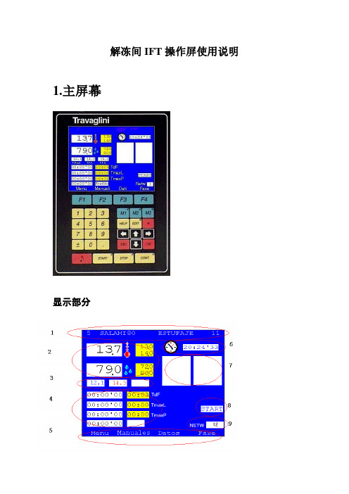
解冻间IFT操作屏使用说明1.主屏幕显示部分➢1: 程序号(5), 程序名(SALAMI80), 调用程序名(ESTUFAJE), 目前运行的子程序序号(11).➢2: 温度值(13.7),温度设定上下限范围(13.0,14.0), 湿度值(79.0), 湿度范围(72.0,80.0).➢3: 其他温度值. 如解冻间, 一般第一个是产品中心温度, 第二个是产品表面温度, 第三个是盘管内温度.➢4: 目前运行工作时间状态. 如TdF表示此子程序的最大持续时间. TmaxL表示最大工作时间, TmaxP表示最大休息时间. 左边白色框内为剩余时间, 右边为设定时间.➢5: 各子菜单名. LIST 主菜单MANUAL 可手动起动项DA TA各项数据PHASE 子程序内容.➢6: 时钟➢7: 工作状态显示.左边是工作状态的时间显示, 右边是各部件起动情况➢8: 设备启动报警显示.➢9: 网络地址操作部分➢F1,F2,F3,F4—对应正上方显示屏显示的内容.➢数字区0~9—为可选择输入数字,小数点及正负号.➢编辑区—M1,M2,M3 为快捷键,可直接启动设备的某些功能。
如一般的设定M1-手动离心风机运行,M2-排风,M3-定时排风。
此项手动运行功能也可在主页面下,按F2(MANUAL)进入。
HELP可以查看各英文缩写的具体含义。
EDIT为编辑键,在需要修改参数时,按此键进行修改。
上下左右箭头可移动光标,或者屏幕,或者数值,或者选择字母等功能。
ESC是退出键。
OK 是确认。
➢报警按钮,当有报警时会有报警声且有灯闪动。
START开机。
STOP关机。
CONT继续。
2.设定程序所有SSC控制面板设定程序的步骤都一样,现以解冻为例第一步按F1 MENU1>Programs 程序2>Alarms报警3>V ersion版本4>Configuration 设置n5>Password密码6>Maintenance维护第二步按1>Programs1>Create/Change program (创建程序)2> Read Program(读程序)3>Program Save(保存程序)4>Program list(程序列表)5>Delete program(删除程序)第三步按1>Create/Change programF1 insert 插入F2 delete 删除F3 list 列表F4 help 帮助第四步按F1 insert第五步选择插入位置,按上下键即可。
E5CN AN EN-H 温度控制器 说明书
前言E5CN/AN/EN-H温度控制器(数字调节器)功能介绍。
下述内容包括功能、性能和使用方法的信息。
·为可选择使用热电偶、铂电阻、模拟量电压输入、模拟量电流输入的多重输入型。
·新增加热冷却控制功能。
·调整功能包括AT(自动整定)、ST(自我整定)选择。
·通过事件输入可对Bank、运行/停止、自动/手动、简易程序的启动/复位功能等进行切换。
·可使用加热器断线检测功能、SSR故障检测功能及加热器过电流功能(E5CN/AN/EN-H带加热器断线功能的机型)。
·可使用通信功能(E5CN/AN/EN-H带通信功能的机型)。
·支持用户进行传感器输入的校正。
·支持用户进行传感输出的校正(E5AN/EN-H带传送输出功能的机型)。
·对应位置比例控制。
(E5AN/EN-H位置比例型)·可使用远程SP输入。
(E5AN/EN-H)·具有防水构造(IP66)。
·符合安全标准(UL/CSA/IEC)及EMC标准。
·通过PV显示色切换,使进程状态一目了然。
本用户手册记述了使用E5CN/AN/EN-H时的功能、性能及注意事项。
事先充分阅读本手册,在充分理解的基础上进行正确的应用。
本手册可经常作为参考,请妥善保存。
有关通信功能的详细说明,请参阅「E5CN-H/E5AN-H/E5EN-H数字调节器通信用户手册」(手册编号:SGTD-737)。
I使用时的注意事项1.品质保证①保证期间本公司的保证期限为从本公司向贵公司提供产品1年后。
②保证范围在上述保证期限内产品出现质量问题,本公司负责免费对故障产品进行维修或更换,用户可以在购买处进行更换或要求维修,但下列情形除外:a) 在产品目录及设计•规格书规定的条件、环境、使用方法外使用而引起故障;b) 本公司产品以外的原因引起的故障c) 非本公司进行的改造或者修理引起的故障d) 未按本公司产品固有使用方法使用的e) 产品投入流通时的科学技术水平尚不能发现的缺陷f) 由于不可抗力等其他非本公司责任导致的另,本条所述保证是指对本公司产品本身的保证,就本公司产品的故障所引起的其他人身和财产的损害,不在本保证范围之内。
控制面板按键操作及屏显功能说明
控制面板按键操作及屏显功能说明控制面板是设备上的一个部分,用于控制和操作设备的各种功能。
它通常位于设备的前面或一侧,并且通常包含一系列按键和显示屏。
以下是控制面板按键操作及屏显的功能说明。
1.电源按钮:这是控制设备的主要开关。
按下此按钮可启动或关闭设备。
在设备启动期间,屏幕上通常会显示设备的名称和品牌等信息。
2.功能选择按钮:控制面板上通常有一行或多行的按钮,用于选择设备的不同功能。
例如,在一台打印机上,功能选择按钮可以包括打印、复印、扫描等选项。
通过按下这些按钮,用户可以选择所需的设备功能。
3.数字键盘:一些设备上有一个数字键盘,用于输入数字、密码或其他与设备操作相关的信息。
例如,在一台复印机上,用户可以使用数字键盘来设置打印的份数。
4.确认按钮:一旦用户选择所需的功能或输入所需的信息,他们可以使用确认按钮来确认选项。
按下此按钮后,设备将执行用户的选择。
5.取消按钮:如果用户选择了错误的功能或输入了错误的信息,他们可以使用取消按钮来撤消操作。
按下此按钮后,设备将取消先前的选择或输入。
6.菜单按钮:此按钮用于访问设备的设置菜单。
通过按下此按钮,用户可以访问设备的各种设置选项。
在菜单中,用户可以更改设备的默认设置、调整屏幕亮度、音量等。
7.上下左右按钮:这些按钮通常位于设备面板的中央或底部。
它们用于在设备的菜单、文件夹或列表中进行导航。
通过按下这些按钮,用户可以在屏幕上浏览不同的选项或文件。
8.回车按钮:在一些设备上,有一个回车按钮用于确认和执行所选操作。
当用户在选项或文件上移动并希望执行该操作时,他们可以按下回车按钮。
9.显示屏:控制面板上通常有一个显示屏,用于显示设备的状态和信息。
这些信息可以包括设置选项、故障代码、任务进度等。
显示屏还可以显示设备的菜单和用户的输入。
10.状态指示灯:控制面板上的状态指示灯用于显示设备的状态。
这些指示灯可以指示设备是否打开、是否正在操作、是否需要更换耗材等。
总的来说,控制面板按键操作和屏显功能使得设备更加易于使用和操作。
- 1、下载文档前请自行甄别文档内容的完整性,平台不提供额外的编辑、内容补充、找答案等附加服务。
- 2、"仅部分预览"的文档,不可在线预览部分如存在完整性等问题,可反馈申请退款(可完整预览的文档不适用该条件!)。
- 3、如文档侵犯您的权益,请联系客服反馈,我们会尽快为您处理(人工客服工作时间:9:00-18:30)。
User guide for EZ-USB Control PanelUser guide for EZ-USB Control Panel.An Overview of the EZ-Usb Control Panel.The EZ_USB Control Panel allows the user to generate USB requests to the Anchor Chips supplied USB driver. Standard USB requests are supported as well as EZ-USB specific requests. The standard USB device requests are documented in Chapter 9 of the USB spec.The control panel supports the following operations:• Get descriptors• Download software• Send/receive bulk data from the screen or a file• Send/receive isochronous data• Loop back testsThe USB devices which are found to be available by the Operating System are identified and presented to the user. Those devices may be selected to operate as the target of some USB operation. A given USB device may have several USB Pipes and Endpoints available to it. The Anchor Chips EZ-USB device, for instance loads a default setting with 12 pipes and endpoints associated with it.When the application is initially started, it checks for available EZ-USB devices on the USB bus. Devices which are found are each given their own window in the main application into which the users may enter commands and view output from the device. Available devices may also be identified by selecting the pulldown menu to the left of the "Clear" button.To start an operation, select the operation from the box next to the "send" button. This will change the toolbar so that it can accept information for that command. Fill in the information and press the "send" button to send the command over the USB bus.{overview.gif}The Application Toolbar.The Application Toolbar has standard buttons such as Cut, Copy, Paste, Save, and Print, as well as an “About” button to get Version information.It contains a “Select Target” button to allow the user to specify that an EZ-USB target is being used, or that an FX2 target is being used. These two targets differ in that Hold/Release is performed differently for each. In addition, a different default monitor file is used for the two targets.It contains a “GPIF Tool” button to launch the GPIF Tool application.{17_tpapp.gif}The Main Screen.The Main screen shows a toolbar containing a dropdown menu of standard USB requests and a "Send" button to initiate transfer of the commands. This "operations" toolbar also contains the Device and Interface identification strings associated with the USB device. It contains a "Clear" button to clear the contents of the output buffer, and a "Load Monitor" button to download the monitor code to the USB Device. The monitor code allows the use of a serial debug monitor while developing target 8051 code.Note: If your screen doesn't contain a "EZusb-0" window, see the troubleshooting chapter below. Below the operations toolbar is a text window which contains the output generated to debug USB transfers. As commands are sent and received, diagnostic text is added to this window. It is a generic text window with the normal operations such as search, save, and print. The USB commands and their parameters are printed out as they are sent or received. When the user selects a USB command from the pull down menu, another ToolBar may be displayed to allow the user to enter parameters for a USB command.{mainscrn.gif}Hot Plugging New DevicesWhen the Control Panel application is started, it checks for USB devices on the bus. If an EZ-USB device is plugged in after having started the application, it will not be recognized immediately. For the new device to be recognized by the application, select "File\Open All Devices" to open a new window with the new device selected and ready to receive commands.The Properties Dialog.The General Page.The Verbose Mode option allows the user to select a more verbose output from the content of transferred messages.The Pop Up Command ToolBars option allows the user to select how they want to view the operation ToolBars. They may view the ToolBars one at a time so the appropriate ToolBar pops up when the operation is selected. Alternatively, they may clear the selection box so that the operation toolbars are all displayed at once. This creates a busier display, but may be desirable when the user has a large screen area or is familiar with the available operations and wants to select them more quickly.Automatically Hold during download, then Run: automates this chore instead of using the HOLD/RUN buttons.Use separate thread for each USB operation: Prevents USB operations from hanging the Control Panel. Max Operations Pending limit: Specifies the maximum number of operations pending. If the user runs up against this limit (for instance by repeatedly trying to read from an empty pipe) then further operations will not be started. The user may increase this limit at any time, thereby allowing them to send an operation which should clear the pending operations (such as writing to an output pipe).{general.gif}The Paths Page.The Monitor File Location.This allows the user to select the default location of the monitor code. See Cypress\USB\Target\Monitor for alternative monitor files. The user can select the default monitor using the browse button, and the selected monitor will be downloaded when the user presses the "Load Monitor" button on the main operations ToolBar.{paths.gif}Exiting the Program.When the User exits by selecting "File/Exit" or by pressing the "x" in the upper right corner, the user may be asked if they wish to save the contents of the output buffer. A dialog box is displayed which allows the user to save the contents of a modified output buffer.File Menu Commands.{menufile.gif}Open All Devices: Poll for available USB devices and enter all available devices into pull-down lists. Then open a view for all devices that were found.Edit Menu Commands.{menuedit.gif}View Menu Commands.{menuview.gif}Window Menu Commands.{menuwind.gif}Options Menu Commands.{menuopt.gif}Tools Menu Commands.{tools.gif}The tools menu will display whatever Cypress tools are installed on your PC. The menu content is variable. Help Menu Commands.{menuhelp.gif}Unary Operations ToolBar.{tbuna.gif}The Unary Operations need no parameters (except the possible selection of a target file).There are several such operations collected on the Unary Operations toolbar as follows:Get Device Descriptor: Get Device Descriptor standard call.Get Configuration Descriptor: Get Configuration Descriptor standard call.Get Pipes: Uses "Get Pipe Info" IOCTL to get the pipe/endpoint configuration information from the driver. The driver maintains this information in memory, so no USB traffic is actually generated from this command.Get String: gets string descriptors (it is hard coded to get the strings with index 1 and 2). This is normally the Manufacturer string index and Product string index (which is seen when you plug in the device). Download: Download a target (*.hex) file.Re-Load: Re-Load the last target file.EEPROM: Select EEPROM file to download file contents to EEPROM.URB Stat: gets the most recent USB Error status reported.Multiple USB errors (Indicated by the generic “Endpoint Error”) map to a single IOCTLError. The IOCTL errors are normally reported directly by the Control Panel, but such a USB errorwill now indicate “Endpoint Error” instead.Pressing URB stat will manually request the last URB (USB Request Block) error.Please be aware that some types of errors (like a bad parameter in the IOCTL) would fail beforegetting to USB, so the error code would be meaningless.Pressing “URB Stat” (as has been done in the screenshot above) will give you the value of the lastUSB error, and will decode the error If possible.Hold: Put 8051 Reset into Hold state.Run: Put 8051 Reset into Release state.Vendor Request ToolBar.{tbvend.gif}The Vendor Request parameters are entered here.NOTE: Please see the EzUsb General Purpose Driver Spec for more detailed information onVendor Specific Request parameters.The Vendor Specific Request parameters are dependant on the program running on the target.For instance, the C:\Anchor\Examples\Vend_Ax.hex program may be loaded on to the Development Board. This implements several Vendor Specific Requests (see the readme file in that diretory).Once the Vend_Ax.hex program is loaded, you can modify the Req Field to send different requests,such as reading the contents of the EEPROM on the Development Board.Request: ID representing request type.Value: Hex value.Index: Index value.Length: Length field.Direction: 0=Out; 1=In.Hex Bytes: Byte field for data.Isochronous Transfer ToolBar.{tbiso.gif}The Isochronous Transfer parameters are entered here.The overall size of an Iso transfer is limited to 1MB.When the Iso Trans button is used for a transfer out, a buffer is filled with incrementing words of ISO data. If you wish to send a file of specific data for the ISO transfer out, you should use the File Trans buttonOn the pipe operations bar.NOTE: See the "EzUsb General Purpose Driver Spec" for more detailed information on Iso Transfers. Pipe: Select Pipe or Endpoint for operation.PktCount: Number of Packets.This is the number of frames of ISO data to read from the device.ISO transfers occur every USB frame (1ms).For example, a PacketCount of 3000 would indicate 3 seconds of ISO data.This parameter must be evenly divisible by the product of the next two parameters that is: (PacketCount mod (FramesPerBuffer * BufferCount)) must be zero.PktSize: Size of Packets in bytes.This is the amount of ISO data to read during each frame.This value usually corresponds to the max packet size of the ISO endpoint, but can be less.BuffCount: Number of buffers to use.This is the number of transfer URBs to use for thistransfer. 2 is a good default value.FrmPerBuff: Frames per buffer.This is the number of USB frames of data to transfer in a single URB (USB Request Block).10 is a good default value.Bulk Transfer ToolBar.{tbblk.gif}The Bulk Transfer (byte mode) parameters are entered here.Pipe/End: Select Pipe or Endpoint for operation.Length: Size of transfer.Blk Loop: Run a loop test by sending data out an OUT endpoint and reading it into an IN endpoint. This requires the presence of a special program running on the EZ-USB device which ties the endpoints together in a loop (currently this will work with C:\Anchor\USB_Ctrl\Examples\ep_pair.hex which ties pipes-endpoints together). Note that this file must be loaded first.Hex Bytes: Hex Data Bytes.Pipe Operations ToolBar.{tbreset.gif}The Pipe Operations parameters are entered here.Pipe/End: Select Pipe or Endpoint for operation.Op: Allows user to specify Pipe Operation.File Trans..: The File Transfer button allows you to select ISO or BULK endpoints as targets of a file based operation. When this button is pressed, You will be prompted for a file name. If you have an OUT pipe selected, the file will be opened and transferred through the OUT pipe. If an IN pipe is selected, the file will be created and filled with the data that comes in the pipe (which will have to be generated by the 8051 somehow). There is a sample file: C:\Anchor\EZUSB\TARGET\Test\64_Count.hex that is a typical hex file, which can be selected to send out an OUT port. It is simple to load the ep_pair, example for instance, and send the 64_count.hex file out over the USB bus. The hex files used are raw hex values which can be generated and viewed with any standard hex editor.Set Interface ToolBar.{tbint.gif}The Set Interface parameters are entered here.Interface: Select Interface Index.Alternate Setting: Select Alternate Setting index.TroubleshootingWhy don't I see an EZ-USB0 window??If the program starts up with a shortened menu and no toolbar, it means thatyou don't have a USB device installed.Since USB is real plug and play, you just have to plug in the device and select"file/update_all_devices" , then "file/open_all_devices" to see it.I tried plugging the device in and selecting open All Devices, but I still don't see it.This indicates that your device isn't loading the driver. Several possible problems are:Device isn't powered. Make sure the jumper near the USB connector is in the "BUS" position.Driver wasn't loaded. Go to the Windows Control Panel, select System/usb devices/anchor dev board. Select "update driver" to re-configure the driver in the registry.USB connector isn't properly connected to your motherboard.Device type programmed in the EEPROM (U9) that doesn't match the ezusb.inf file. If you reprogrammed the EEPROM and can't recover, you can pull the EEPROM off of the board to revert to the VID/PID of 547/2131.My software says that it loads, but it doesn't run.Make sure that your file is in hex format. This is always the preferred format.If you are using a bix file, you can only download to the lower 8K of memory (0-1fff).For larger images, always use the hex file format.The memory map switches are not in the proper position.Switch 3 should be ON and switch 4 should be OFF to use all of the external RAM (for Series 2100).You plug in the EZ-USB Development Board and the system respondswith a message saying "unknown device".Please perform the following procedure (for Win9x only):1.) Unplug the development board.2.) Remove (or rename) file"C:\Windows\System\Inf\Drvidx.bin"3.) Remove (or rename) file"C:\Windows\System\Inf\Drvdata.bin"(These are the 2 largest files in the INF directory).4.) When you plug the EZ-USB Development Board backinto the PC, it should be recognized and loaded automatically.。