DSP502H说明书-日文
500系列话筒前置放大器502快速入门指南说明书

500 SERIES MICROPHONE PREAMPLIFIER 502 500 Series Modular Midas Microphone Preamplifier with Classic XL4 FiltersV 1.0带有此标志的终端设备具有强大的电流, 存在触电危险。
仅限使用带有 1/4'' TS 或扭锁式插头的高品质专业扬声器线。
所有的安装或调整均须由合格的专业人员进行。
此标志提醒您,产品内存在未绝缘的危险电压, 有 触电危险。
此标志提醒您查阅所附的重要的使用及维修说明。
请阅读有关手册。
小心为避免触电危险, 请勿打开机顶盖 (或背面挡板)。
设备内没有可供用户维修使用的部件。
请将维修事项交由合格的专业人员进行。
小心为避免着火或触电危险, 请勿将此设备置于雨淋或潮湿中。
此设备也不可受液体滴溅, 盛有液体的容器也不可置于其上, 如花瓶等。
小心维修说明仅是给合格的专业维修人员使用的。
为 避免触电危险, 除了使用说明书提到的以外, 请勿进行任何其它维修。
所有维修均须由合格的专业人员进行。
1. 请阅读这些说明。
2. 请妥善保存这些说明。
3. 请注意所有的警示。
4. 请遵守所有的说明。
5. 请勿在靠近水的地方使用本产品。
6. 请用干布清洁本产品。
7. 请勿堵塞通风口。
安装本产品时请遵照厂家的说明。
8. 请勿将本产品安装在热源附近, 如 暖气片, 炉子或其它产生热量的设备 ( 包括功放器)。
9. 请勿移除极性插头或接地插头的安全装置。
接地插头是由两个插塞接点及一个接地头构成。
若随货提供的插头不适合您的插座, 请找电工更换一个合适的插座。
10. 妥善保护电源线, 使其不被践踏或刺破, 尤其注意电源插头、多用途插座及设备连接处。
11. 请只使用厂家指定的附属设备和配 件。
12. 请只使用厂家指定的或随货销售的手推车, 架子, 三 角架, 支架和桌子。
若使用手推车来搬运设备, 请注意安全放置设备, 以 避免手推车和设备倾倒而受伤。
Philips DDL 502-13HBS 智能轮栓说明书

DDL502Q00BB and compact designWith effortless setup to save your timeFeaturing a sleek and compact design, Philips DDL502-13HBS allows for fast andsimple setup with no mortise required. Perfect for home, studios, offices, or stores.Ditch the keys and enjoy easy access to your space with this product.Smart life "locked" with excellenceInstant unlock with one touchManage your locks with our all-in-one solutionSecure protection, smart embeddedA utomatic locking upon door closedSafeguarding your homeEasy life goes beyond thisSay goodby to the key-only eraEffortlessly meet your diverse needsHighlightsSemiconductor fingerprintUnlock the door with a single touch of your fingertip using the semiconductor fingerprint sensor of the DDL 502-13HBS . With arecognition speed no more than 0.5 seconds *,enjoy a fast and convenient door -opening experience .A pp *controlBy connecting the DDL 502-13HBS lock to the Philips EasyKey Plus A pp , you can access information such as battery level and activity history , and even unlock the door with a single touch on your phone from up to 10 meters *away .HallsensorOur lock comes with Hall sensor technology to automatically lock the door as soon as it 's closed in auto mode . The deadbolt pops up instantly , providing you with peace of mind as you leave .MultiplealertsOur DDL 502-13HBS smart lock comes with multiple alerts including anti -disassembly ,system lockout , abnormal deadbolt , and privacy mode alerts . It not only provides constant protection for your home , but also keeps you updated on the condition of the door lock in real time for your convenience .3 unlockingmethodsOur DDL 502-13HBS smart lock supports three unlocking methods : fingerprint , PIN code , and mobile app . This allows you to e ffortlessly and securely unlock your door in any situation ,meeting your various unlocking needs . With our smart and convenient unlockingexperience , you 'll enjoy the ultimate peace of mind .Switch between 5languagesPhilips DDL 502-13HBS smart lock features real human voice navigation *, supporting fivelanguages including Chinese , English , Spanish ,Portuguese , and Indonesian . With simpleoperation and easy language switching , it can meet the diverse needs of users .SpecificationsA ccess SolutionFingerprintPassword/PIN CodeDesign & A ppearanceColor: Obsidian black Fingerprint Sensor: Semiconductor Handle: No handleMain Material: A luminium alloy Power SpecificationBattery Type: A lkaline BatteriesEmergency Power Supply: 5V power bankPower Supply: 4 AA batteriesTime of Use: 10 months*InstallationDoor Opening Direction: Left inward opening,Left outward opening, Right inward opening,Right outward oepningDoor Thickness: 30-50 mm, 50-90 mm, Otherrange*Door Type: A ntitheft door, Wooden doorEasy OperationVoice Guide: Human voice guide* 0.5S data source:Internal test report.* A pp: refers to the "Philips EasyKey Plus" app. (Note: Thelock information can only be uploaded to the app whenthe lock is connected to the app.)* 10 meters: the distance is based on internal laboratorytesting and may vary slightly depending on usageenvironment and network signal. For more accurateresults, please be subject to the actual usage.* Real human voice navigation: defaulting to English andcan be easily switchable to other languages through thelock's settings.* These are experimental data, and the battery-lastingtime is subject to actual using scenarios.* The effect of the digital keypad showed in the photos ofthis product may be inconsistent with the actual displayeffect. Please be subject to the digital keypad displayingstatus under the actual usage scenarios.© 2023 Koninklijke Philips N.V.A ll Rights reserved.Specifications are subject to change without notice. Trademarks are the property of Koninklijke Philips N.V. or their respective owners.Issue date 2023‑05‑20 Version: 1.0.112 NC: 8670 001 90342E A N: 69 71318 50445 7 。
裕华YHIP502(Ex)防爆号筒式扬声器使用说明书

常州裕华常州裕华电子设备制造有限公司XK06-123-00251生产许可证编号:安装、使用前请仔细阅读使用说明书。
1. 安装1、安装、使用前请仔细阅读使用说明书,遵守警告事项。
2、在对设备进行维护和检修之前,请务必切断电源。
3、避免在有油烟、灰尘严重、高温、结露的场所打开设备。
4、请按本说明书要求正确安装电缆,否则有可能产生故障。
5、在对设备进行维护时,一定要注意对隔爆面的保护;避免金属碎屑或其它物质进入设备内部。
6、请勿对设备进行分解或改造。
2. 环保本公司所生产的各类产品,其中有可能包含对环境造成污染的零部件,如电路板、电子元器件、塑料制品、润滑油脂等,当设备维护或报废时,请注意对这些污染源进行收集、控制,不要随意丢弃,应当移交给相关环保部门进行处理,以免对环境造成不良影响。
2目录1. 概述: (4)2. 技术指标 (4)2.1型号组成 (4)2.2认证 (4)2.3电气指标 (4)2.4机械指标 (5)2.5环境条件 (5)2.6产品尺寸 (5)2.7安装尺寸 (6)3. 安装 (6)3.1电缆的处理 (6)4. 防爆结构说明 (7)5. 设备安装注意事项 (8)6. 运输、贮存 (8)7. 安装件及附件 (8)8. 质量保证 (8)9. 公司声明 (9)341. 概述:YHIP502(Ex )防爆号筒式扬声器可与各种功放设备配套使用,作扩音呼叫或报警用。
YHIP502(Ex )防爆号筒式扬声器是严格按GB3836.1-2000《爆炸性气体环境用电气设备第1部分通用要求》和GB3836.2-2000《爆炸性气体环境用防爆电气设备第2部分:隔爆型d 》等标准设计制造的,隔爆腔外壳采用全不锈钢结构,防护等级IP54级。
YHIP502(Ex )防爆号筒式扬声器是与YHIP700系列数字型防爆工业话站配套使用的通讯系统中的扩音单元,应用于大型厂矿企业。
可用于有爆炸性危险环境的场所,如石油、化工、仓储、港口、矿山等行业。
BOSE 502 A, 502 B型 Panaray系列专业扬声器 说明书
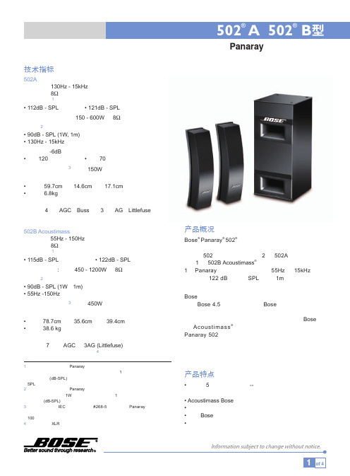
502A 列阵扬声器设计用于不同的安装场合,使用其 10 倍于 安全额定值的连接安装点及 Bose 悬吊和安装附件。障板与后 面板用高强度塑料制成,扬声器面罩格网用耐用钢板网制成, 罩面有专业灰和北极白两种颜色可选择,箱体和面罩均可按 室内装饰要求重新涂色。
100 小时后,该扬声器必须无明显可见的损坏,或产生可测量的缺陷。 4 国际版本使用XLR型接口。
产品概况
Bose® Panaray® 502® 系统是一个全模块化系统,体现了 扬声器列阵、低频换能器和系统控制技术的巨大进步。 基本的 502 系统由单独出售的 2 只 502A 受控列阵扬声 器,1 只 502B Acoustimass®“音响气量流”低音音箱和 1台 Panaray 系统控制器组成,在 55Hz 至 15kHz 范围 提供最大 122 dB 的峰值 SPL (距离 1m,以最大推荐放 大功率驱动)。
Panaray系统数字控制器占据一个机架单位高度,为502A 和502B提供分频功能、有源电子均衡和双声道信号处理 功能。
选配的插卡可插入Panaray® 系统数字控制器,使 502A 列 阵扬声器可与 Bose AcousticWave® 声波大炮组合使用。
Panaray502 系统拥有完整的吊装和安装附件,适于广泛 的场合吊装和安装 502A、502B 扬声器。
位于箱体背板上的输入接口由螺钉接线片组成。
箱体由高强度高密度树脂浸泡乙烯包层颗粒板制成, 外壳尺寸为:78.7cm 高 x 35.6cm 宽 x 39.4cm 深 重量为 38.6 公斤。
低音音箱在 55Hz至150Hz 的最大声输出为 115dB-SPL, 测量时输入全频粉红噪声,达到额定功率时距扬声器 1m 处测得。其功率处理能力为 450W 连续功率,按 IEC 噪 声 100 小时为基准。
博世IPX20 4多通道安装DSP音频放大器说明书
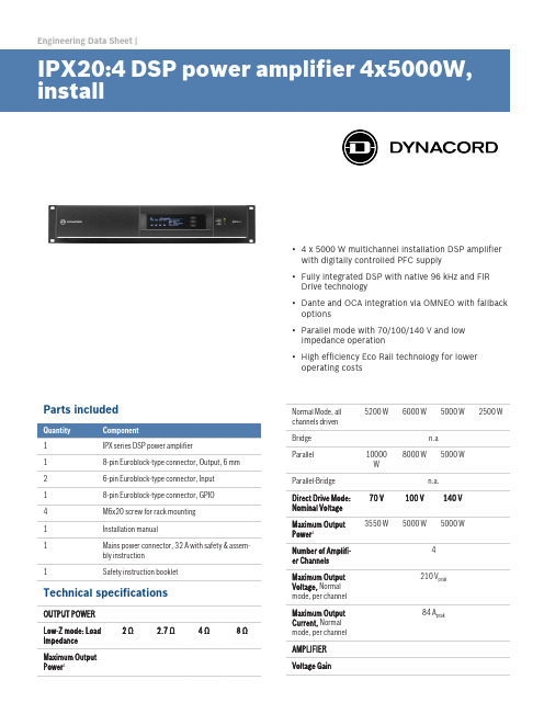
Engineering Data Sheet |▪ 4 x 5000 W multichannel installation DSP amplifierwith digitally controlled PFC supply▪Fully integrated DSP with native 96 kHz and FIRDrive technology▪Dante and OCA integration via OMNEO with fallbackoptions▪Parallel mode with 70/100/140 V and lowimpedance operation▪High efficiency Eco Rail technology for loweroperating costsParts included1IPX series DSP power amplifier18-pin Euroblock-type connector, Output, 6 mm 26-pin Euroblock-type connector, Input18-pin Euroblock-type connector, GPIO4M6x20 screw for rack mounting1Installation manual1Mains power connector, 32 A with safety & assem-bly instruction1Safety instruction bookletTechnical specificationsOUTPUT POWERLow-Z mode: LoadImpedance2 Ω 2.7 Ω 4 Ω8 ΩMaximum OutputPower1Normal Mode, allchannels driven5200 W6000 W5000 W2500 WBridge n.aParallel10000W8000 W5000 WParallel-Bridge n.a.Direct Drive Mode:Nominal Voltage70 V100 V140 VMaximum OutputPower13550 W5000 W5000 WNumber of Amplifi-er Channels4Maximum OutputVoltage, Normalmode, per channel210 V peakMaximum OutputCurrent, Normalmode, per channel84 A peakAMPLIFIERVoltage GainLow-Z mode, ref.1kHz32.0 dB, adjustable 20.0-44.0 dB Direct Drive mode33.2/36.2/39.2 dB for 70/100/140 V Input SensitivityLow-Z mode, Max.Output Voltage13.7 dBu (3.73 V), adjustable 1.7-25.7 dBu Direct Drive mode 6 dBu (1.55 V), fixedTHD3 dB below max,AES17, 1 kHz< 0.05 %DIM 1003.15 kHz, 15 kHz< 0.15 %IMD-SMPTE60 Hz, 7 kHz< 0.15 %Crosstalkref. 1 kHz, 12 dBbelow Max, 8 Ω< -80 dBFrequency Re-sponseref. 1 kHz, analog into speaker out20 Hz to 20 kHz (±1.0 dB)Damping Factor20 Hz to 200 Hz, 8Ω> 400Output Stage Top-ologyClass D, fixed frequencySignal to Noise Ra-tio AmplifierA-weighted, analoginput115 dBA-weighted, digitalinput118 dBOutput NoiseA-weighted, analoginput< -70 dBuA-weighted, digitalinput< -73 dBu CONNECTIVITYAnalog Audio In-put/ThruType 2 x 6-pin Euroblock, male Maximum Input Lev-el+21 dBuInput Impedance, active balanced 20 kΩReference levelequal to digital in-put+21 dBu for 0 dBFSSpeaker Output 1 x 8-pin Euroblock, 6 mm, femaleGENERALPower Consump-tionRated power con-sumption (see BTUtable)2250 W1/8 Maximum Out-put Power at 4 Ω2850 WIdle Mode (no inputsignal)110 WStandby Mode< 19 WDimensions(W x H x D), mm483 x 88.1 x 514.2Weight18.3 kg (40.3 lb)Shipping Weight20.5 kg (45.1 lb)DIGITAL SIGNAL PROCESSINGSampling rate48 kHz/96 kHz, OMNEO/Dante synchronizedSignal delay/laten-cyAnalog In to Speak-er Out, 48 kHz/96kHz0.70 ms/0.53 msDante Network La-tencytyp. 1.00 msSignal ProcessingUser EQ12 filters per channel, selectable as PEQ, Lo-Shelv, Hi-Shelv, Lo-ShelvQ, Hi-ShelvQ, Hi-Pass,Lo-Pass and Notch; 2 filters of them with addi-tional asymmetric filter typeUser Delay0 to 2000 ms per channel (units: µs, ms, s, cm,m, inches, feet)Array EQ 5 filters per channel, selectable as PEQ, Lo-Shelv, Hi-Shelv, Lo-ShelvQ, Hi-ShelvQ, Hi-Pass,Lo-Pass, and All-PassArray Delay0 to 500 ms per channel (units: µs, ms, s, cm,m, inches, feet)Speaker EQ10 filters per channel, selectable as PEQ, Lo-Shelv, Hi-Shelv, Hi-Pass, Lo-Pass and All-PassSpeaker X-Over Hi-Pass, and Lo-Pass per channel,6/12/18/24/30/36/42/48 dB Bessel/Butter-worth, 12/24/48 dB Linkwitz-Riley; AlignmentDelay, 0 to 20 ms per channelSpeaker FIR Up to 1025 taps, Linear Phase Filter, LinearPhase Brickwall X-OverSpeaker Limiters Peak Anticipation Limiter and RMS/TEMP Limit-er per channelOther Functions Source Selection and Mix, Level, Mute, Polarity,Sine and Noise Generator, Pilot Tone Generatorand Detection, Level Meters, Impedance Meas-urement and Load MonitoringMemoryDSP Presets 1 Factory + 20 UserSpeaker-Pool Pre-sets30 Speaker SettingsSource Supervi-sion and Fallback Pilot Tone supervision at Analog and OMNEO/ Dante inputs, switchover to alternative Source SelectionCONNECTIVITYNetworkType 2 x Neutrik EtherCON/RJ45, redundant PRI-MARY/SECONDARYGeneral1000base-T/100base-TX, integrated switch Network Audio In-puts8 channels, 48/96 kHz, OMNEO/Dante formatNetwork Audio Out-puts (Monitor)2 channels, 48/96 kHz, OMNEO/Dante format Mains Input 1 x Neutrik powerCON-HCGPIO Control PortType 1 x 8-pin Euroblock, malePorts and Operating Modes 3 x GPIO, switchable Analog In/Digital In/Digital OutAnalog Input Range0 V to +13 V, 40 kΩ input resistance Digital Input Limits ON: < 1.5 VOFF: > 2.0 V, internal Pull Up (10 kΩ) Digital Outputs ON: Output switched to GND, max. 200 mAOFF: Open Collector (40 kΩ to GND)Reference Voltage Output +10 V, max. 200 mA, supervised, short circuitprotectedREADY/FAULT con-tactGalvanic isolated relay, max. 30 VDC/500mADCGENERALUser InterfaceDisplay Black/white OLED 256 x 64 pixelFront panel indica-tors4 x status LEDs (POWER, STANDBY, FAULT,OMNEO)Front panel operat-ing elements3 buttons (UP, ENTER, DOWN)Rear panel indica-tors1 x status LED (STATUS)Rear panel operat-ing elementsMains SwitchPower Require-ments100 V to 240 V, 50 Hz to 60 Hz ACPower Supply Top-ologySwitching Mode Power Supply with digital con-trolled Power Factor CorrectionProtections Audio Limiters, High Temperature, DC, HF,Short Circuit, Back-EMF, Peak Current Limiters,Inrush Current Limiters, Turn-on Delay, MainsCircuit Breaker Protection, Mains Over-/Undervoltage ProtectionCooling Front-to-rear, temperature controlled fans, su-pervisedAmbient Tempera-ture Limits+5 °C to +40 °C (+40 °F to +105 °F)IEC ProtectionClassClass I (grounded)ElectromagneticalEnvironmentE1, E2, E3Color BlackAmplifier at rated conditions, Low-Z Normal operationmode, all channels driven, 4 Ω loads, Analog input, 32dB Gain, 48 kHz sample rate, unless otherwisespecified.1Test signal for max. output power according IHF-A-202 (Dynamic-Headroom, burst 1 kHz/20 ms on/480ms off/low level -20 dB).Block diagram: IPXDimensions: IPXOrdering informationIPX20:4 DSP power amplifier 4x5000W, installDSP power amplifier 4x5000W @ 4 ohms, 8 OMNEO/Dante inputs, 4 analog inputs, hi-z direct drive, GPIOs, euro-block connectors, 100 - 240 V, blackOrder number IPX20:4PD32-EU Power distro 3x32A, 230V, CEE 32APower distribution for 3x 32A and 3x 16A, CEE32Amains connector, 3-phase 230/400V, European region, blackOrder number PD32-EUPD30-US Power distro 3x30A, 208V, NEMA L21-30Power distribution for 3x 30A and 3x 15A, NEMAL21-30 mains connector, 3-phase 208V, North American region, blackOrder number PD30-USPCO32A30-US Power cord, powerCon32/NEMA L6-30Power cord, powerCON32 to NEMA L6-30 mainsconnector, 2m, black Order number PCO32A30-USPCO32A16-EU Power cord, powerCon32/CEE7/7 Power cord, powerCON32 to CEE7/7 (Schuko, 16A) mains connector, 2m, blackOrder number PCO32A16-EUPCO32A16-UK Power cord, powerCon32/BS1363 Power cord, powerCON32 to BS1363 (UK-plug) mains connector, 2m, blackOrder number PCO32A16-UKPCO32A10-AU Power cord, powerCon32/AU3-pin10APower cord, powerCON32 to AU, 3-pin 10A mainsconnector, 2m, blackOrder number PCO32A10-AUDC-RMK15 RMK-15Rack Mount Kit for amplifiers, Length 15,5“; 1L/1ROrder number DC-RMK15Germany:Bosch Sicherheitssysteme GmbH Robert-Bosch-Ring 585630 GrasbrunnGermany Bosch Security Systems, Inc.130 Perinton Parkway Fairport, NY 14450USA© Bosch Sicherheitssysteme GmbH, 2018 | Data subject to change without notice Document Number | Vs2 | 24. Apr 2018。
瑞尔科技 'SS-H' 压力开关产品说明书
“SS-H”PRESSURE SWITCH OPERATION MANUAL (4HL2/4HH2) 3/01 1.0 INTRODUCTIONThe Ruelco “SS-H” hydraulic pressure switch is a two way bleed valve which is operated by pressure acting on a piston opposing an adjustable spring force. It functions as either a normally closed or normally open valve. Pressure applied to the sense port will cause the valve to operate.The Model 4HH2 operates as a normally open valve and is called a high switch. If sense pressure acting on the piston is at normal levels, it is insufficient to overcome the spring force. The middle o-ring on the spool is positioned below the bent grooves on the bottom sleeve, thus preventing the instrument pressure from passing to the “Vent” port of the switch body. When the pressure acting on the piston becomes large enough to overcome the spring force, the spool shifts and the center o-ring moves in between the vent grooves on the bottom sleeve. Instrument pressure at the “In” port “Bleeds” into the reservoir through the “Vent” port.The pressure switch “Bleed” action is the same for Model 4HL2. For this model of operation, the switch acts as a normally closed valve and is called a low switch. When normal sense pressure is acting on the piston, the center o-ring on the spool is above the vent grooves in the top sleeve, thus preventing the instrument pressure from passing to the “Vent” port of the switch body. When the sense pressure decreases to an abnormal level, the spring force shifts the spool and the middle o-ring on the spool becomes positioned in between the vent grooves in the top sleeve. Instrument pressure at the “In” port, “Bleeds” into the reservoir through the ‘Vent” port. Changing the sense pressure value when the switch is used as either a high or low id done by altering the force of the spring, the size of the sense piston force is accomplished by turning the spring cap to increase or decrease the spring compression. The piston diameter is changed by adding or removing o-rings on the piston or changing the piston.2.0 INSTALLATIONThe “SS-H” can be panel mounted (with optional panel mount nut) or supported by piping from the sense port in either verticalor horizontal positions. If the switch is mounted horizontally, it is recommended that the small vent holes in the side of the switch body be oriented in a downward position. This will prevent any debris from accumulating in the spring cavity or above the sense piston.Proper PIPE thread sealant should be used on any pipe fittings threaded into the pressure switch ports. If stainless steel fittings are used, a sealant that will prevent galling is required. When the switch is mounted using the ½” NPT base connectionis adequately tightened, DO NOT loosen the body from the base or re-position the ports. Instead, remove the switch and re-make the ½” NPT connection.3.0 DISASSEMBLY (See Spec Sheet)Tools and materials required for proper disassembly, repair and assembly are as follows:1. 7/8”, 1” and 1-5/16” open endwrenches or two crescent wrenchesof adequate size.2. Smallpliers.3. For switches using ¼” diameterpiston, 1 ¼” open end wrench or asuitable crescent wrench.4. High quality silicone base lubricant.5. An appropriate safety solvent.3.1 PARTIALDISASSEMBLYA) SpringRemoval3.1.1 If the switch is installed in anoperating instrument system, it is notnecessary to remove any instrumentsupply or sense pressure. If the unitis a high switch, it will trip whenchanging the spring. If it is a lowswitch, it will not trip when changingthe spring. Precautions should betaken to avoid any unwantedreactions in the instrumentationsystem.3.1.2 To obtain access to the spring (Item2), rotate the lock ring (Item 4)clockwise to loosen it from the springcap (Item 1).3.1.3 Rotate the spring cap (Item 1)counterclockwise until it isdisengaged from the switch body(Item 10).3.1.4 Remove the spring from its cavity inthe switch body. If the parts tube(Item 3) is inside the spring, careshould be taken not to lose it.3.1.5 Follow the procedures in repair andassembly section (Steps 4.15 and4.16) of this manual re re-install thespring.B) PistonRemoval3.1.6 If the switch is panel mounted, it isnot necessary to remove it from thepanel. It will be necessary todisconnect any piping or tubing fromthe base that would prevent thebase from being removed. When theswitch is supported by the ½” NPTconnection on its base (Item 16),disconnect any piping or tubing fromthe switch body that would preventits removal from the switch base.CAUTION: Be sure that allinstrument or sense pressures arecompletely bled to zero beforedisconnecting any piping or tubing.3.1.7 Use the appropriate wrenches tohold and loosen the base from theswitch body. Unthread the basecompletely from the switch body.3.1.8 Use the small pliers and grip theraised ridge on top of the piston(Item 15) and pull it from the switchbase (Item 16).3.1.9 If the ¼” diameter piston (Item 19) isinstalled and must be removed fromthe large piston, use the properwrench to hold the ¼” diameterpiston and grip the large piston withthe pliers at the small diameterabove the groove for the .5” pistono-ring (Item 18). Rotate either onecounterclockwise to loosen andseparate the pistons.3.1.10 Remove the installed o-ring from thepiston.3.1.11 Procedures for re-installing thepiston o-rings are in the repair andassembly procedure of this manual.3.2 FULLDISASSEMBLYNOTE: Use the following instructions to completely disassemble the pilot for repair and cleaning. CAUTION: Be sure that all instrument or sense pressures are completely bled to zero before disconnecting any ping or tubing.3.2.1 Follow the procedures stated underpartial disassembly to remove thespring and pistons.3.2.2 Remove the spool (Item 14) from theswitch body. If it is necessary, usethe small pliers and grip the smallend of the spool. Removing thespool also removes the bottomsleeve (Item 13).3.2.3 To remove the top sleeve (Item 8),an o-ring pick (pointed prying tool)can prove useful. Just insert the pickinto one of the .041 holes in the topsleeve and pull the sleeve out. Notethat while using the pick, care shouldbe taken not to scratch the bore onthe top sleeve.3.2.4 The seals on the shaft and sleevesmay now be replaced as perinstructions given in the repair andassembly section of this manual.。
ZH-502说明书-0925

能接收外部时间基准信号, 并按照要求的时间准确度向外输出时间同步信号和时间信息的系统。 注:时间同步系统通常由主时钟、若干从时钟、时间信号传输介质组成。 4) 时间同步装置 time synchronising device
时间同步装置又称时钟装置,包括主时钟和从时钟。 5) 主时钟 master clock
6. 7.
7.1. 7.2. 7.3.
系统选型表........................................................................................................19 装置的安装........................................................................................................21
5.
5.1. 5.2.
工作状态指示.................................................................................................... 18
指示灯............................................................................................................................. 18 LCD 显示........................................................................................................................ 18
JK Audio innkeeper LTD Digital Hybrid ii 用户手册说明书
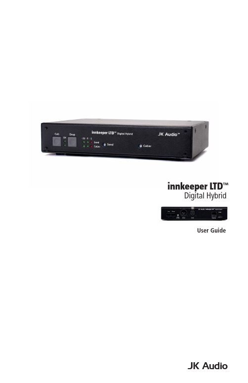
JK AudioUser Guideinnkeeper LTD ™Digital Hybridii innkeeper LTD™ Digital HybridThank YouThank you for purchasing a JK Audio innkeeper LTD Digital Hybrid. Please read this guide for instructions on setting up and using your new product.Getting AssistanceIf you have technical or application questions: Call us at:815-786-2929 Email us at:*******************Or check out our FAQ section for answers to common questions.Warnings & Safety Precautions• Read and keep these instructions.• Follow all instructions.• Clean only with a soft dry cloth.• Refer all servicing to qualified service personnel.• Heed all warnings.Warning: Do not install near any heat sources such as radiators, heat registers, stoves, or other apparatus (including amplifiers) that produce heat.Warning: Do not defeat the safety purpose of the three-prong grounding type plug. If the provided plug does not fit into your outlet, consult anelectrician for replacement of the obsolete outlet.Warning: Do not use this unit if the electrical power cord is frayed or broken. The power cord should be routed so that it is not likely to bewalked on or pinched by items placed upon or against it.To reduce the risk of fire: Use only No. 26 AWG or larger telecommunication line cord.To reduce the risk of fire or electric shock: Do not expose thisapparatus to rain or moisture. WelcomeContents iiiContentsLimited WarrantyThe innkeeper LTD is covered by a 1 year warranty to be free from defective workmanship and materials. To obtain service, contact JK Audio by phone or email for return authorization. Once authorized, you will carefully pack and ship the faulty product and all accessories to us. You will pay for shipping to us and we will pay for return back to you.This warranty does not cover damages due to accident, weather, fire, flood,earthquake, misuse, unauthorized repairs or modifications, or damages occurred in shipping, only defective workmanship or materials.There are no expressed or implied warranties which extend beyond the warranty here made.16 bit DSP TechnologyAuto-Answer (Switchable On/Off)Proprietary Auto Null Algorithm (50 dB null)Send XLR Line InputCaller XLR Line Output Front Panel Off-Hook LEDGuest Module 1 Remote Control Jack Send and Caller Signal Level LEDs Send and Caller Volume Controls Rack MountableFeaturesUniversal Power Supply with Detachable Cord RJ11 Phone CordWhat’s in the Box?Featuresiv innkeeper LTD™Digital HybridOverview Introducing the innkeeper LTD™Innkeeper LTD allows you to send line level signals into the phone line while maintaining excellent separation between your voice and the caller. Thebalanced XLR output jack contains only the caller’s voice, making this the perfect companion to mixers, consoles, and PA systems that demand talk show qualityaudio from a phone line.The digital hybrid connects audio signals to a standard analog phone linewithout the transmit/receive crosstalk common to analog hybrids. Its DigitalSignal Processor (DSP) continuously monitors both the phone line and audiosignals to deliver excellent separation. This proprietary, dual-convergence echo canceller algorithm can achieve separation typically exceeding 50 dB withoutany setup and without sending a noise burst down the line. While this may sound complicated, it’s all done automatically during every call.Ready to go?The innkeeper LTD controls and connectors are clearly marked and ready for operation. If this is your first exposure to a hybrid, we suggest that you read theentire manual to allow you to take advantage of all these features.Any Questions?Before you pick up the phone... Please thumb through the rest of this manual.You might find those deep technical questions are covered on later pages.Overview1Getting to Know Your innkeeper LTD1324567Controls & Indicators1. Call ButtonTakes the line off-hook; press this button to answer a call or you can direct acall from your aux phone through the hybrid.2. OH LEDLit when you are on line with a call (off-hook).3. Drop ButtonPress this button to drop (hang up) a call.4. Signal LEDsSend LEDs represent the signal level going out to the telephone line.Caller LEDs represent the signal level coming from the phone line,after the DSP.5. Send LevelAdjusts the signal that you are sending down the telephone line.6. Caller LevelAdjusts the level of the incoming caller’s audio as it is going out the outputjacks.7. Power LEDLit when unit is plugged in and receiving power.2innkeeper LTD™Digital HybridGetting to Know Your innkeeper LTD 1324567 ArrayInputs & Outputs1. Phone LineConnect to a standard, single line, analog telephone line.2. Aux PhoneConnect a single line analog telephone for call setup / dialing, or producercall screening.3. Auto AnswerWhen enabled, innkeeper LTD automatically answers an incoming call andthen disconnects after the caller hangs up. Auto answer will occur on thefirst ring.4. Caller OutputMale balanced XLR output contains only the callers voice.5. Send InputFemale balanced XLR input for signals going into the phone line.6. Remote Control Jack8-pin modular RJ-45 jack for connection to the optional JK Audio GuestModule 1 Remote Keypad or your broadcast console switch contacts (seepage 7). Do not connect this jack to your computer network port.7. Power JackFor connection only to the supplied 9VDC regulated power supply.Controls & Indicators3Getting ConnectedConnecting to a Single Line Phone1. Connect the supplied RJ-11 phone line cable between the jack marked<Line> and your wall jack. Be sure this jack supports standard single lineanalog telephone operation.2. You may want to connect an auxiliary telephone to the innkeeperLTD <Phone> jack so you can dial out and set up calls, or use the<Auto-Answer> feature to answer incoming calls.Connecting to a Mixer (Mix Minus Caller)Note: A mix-minus signal is an audio signal that contains a mix of your local microphones plusany other audio, minus the Caller’s own voice. Sending the Caller’s audio back to the innkeeper LTD will cause an echo, or feedback.3. Connect the innkeeper LTD <Caller> output to any Line input on the mixer.4. Connect your microphone(s) to the mic inputs on your mixer.5. Connect the mixer’s Mix-Minus bus or Aux Send output (this may be labeledFX or Mon but any Aux bus will work) to the <Send> input on innkeeper 1rx.Set the innkeeper 1rx <Mic/Line> switch to the Line position.6. If your mixer doesn’t have a mix-minus bus: Whichever input channelyou have the <Caller> connected to, turn the corresponding Aux control tominimum. All Aux controls for other channels should be set for audio sentto the phone line. Each Aux Send bus is completely separate from all otheroutputs, so these Aux controls will not affect what is heard on the Mainoutputs or on any other Aux buses.Tip: Using an Aux Send bus that is Pre-Fader allows you to control the levels of eachchannel to the main output without affecting what is sent to the phone line.7. Connect your headphones to the mixer.8. Use Main Outputs to send audio to recording device or broadcastingequipment inputs.4innkeeper LTD™Digital HybridCompleting Setup9. Connect the supplied DC power supply to the back of the innkeeper 1rx and then to an AC power outlet.This device should be connected to an adequate surge protectivedevice at all times both for the power connector and for thetelephone line to avoid damage from lightning or electrical surges.10. Adjust the <Send> level controls so that you consistently light the green -20 dB and -9 dB and rarely light the red -3 dB peak Send LED. Theseflashes should occur only during loud speech bursts. If the red LED stayslit for extended periods you can assume that much of your speech is beingclipped or distorted. Set the <Caller> control for good recording level of thecaller audio at the output jack.5Getting ConnectedOperationAuxiliary TelephoneAn auxiliary telephone provides you with an easy way to dial out or set up your calls. innkeeper LTD will disconnect the auxiliary telephone when you press the <Call> button. If you need to take the call back on the aux telephone, simply pick up the telephone handset before the innkeeper LTD’s <Drop> button is pressed.To use an auxiliary phone equipped with a “Hold” feature to place or screen acall, first set up the call and place the call on hold. When you are ready to take the call on Innkeeper LTD, press the <Call> button on the innkeeper LTD andyour telephone will automatically release the hold.Your phone will operate as a normal telephone anytime you are in Drop mode.Leaving the hybrid connected between the wall jack and your telephone will not affect normal use of your phone. Audio will only pass through the hybrid whenyou press the <Call> button.Optional Jumper SettingsIf the incoming Caller level is too high and peaking the red -3 dB LED, youmay need to change the setting of an internal jumper. Disconnect power fromthe hybrid and remove the cover of the innkeeper LTD to locate Jumper 1. The default position for this jumper is closed (covering both pins). Changing thejumper to the open position (either remove the jumper or cover just one pin) will provide 6 dB attenuation of the incoming audio signal.Auto-AnswerThe <Auto-Answer> feature will answer on the first ring. When <Auto- Answer> is enabled, you can still make calls manually using the <Call> button.When finished, you can either drop the call manually or allow the call toAuto-Disconnect. innkeeper LTD will look for a CPC disconnect signal from the phone company to determine when a call has disconnected. This can take up toa minute.6innkeeper LTD™Digital Hybrid7Remote ControlRemote Control Remote Control JackThe RJ-45 jack on the back of the innkeeper LTD provides connection to anoptional JK Audio Guest Module 1 remote control, or it can be wired to the switch contacts on your broadcast console. Do not connect this jack to the network port on your computer.RJ-45 Pinout :1: Ground 2: Call / Drop Control (main control pin) 3: Ring / OH LED 4: DTMF Input 5: +4.3 VDC 6: Reserved 7: Reserved 8: ReservedTo take innkeeper LTD off-hook , momentarily connect pin 2 to pin 5 (power) through a 100 ohm ¼ watt resistor.To release (Drop) the phone line , momentarily connect pin 2 to pin 1 (ground) through a 100 ohm 1/4 watt resistor.Pin 3 contains a 4.3 VDC, 40 mA current limited output to drive a signal LED. We suggest adding a 200 ohm ¼ watt resistor in series with an LED connected to ground.Pin 5 supply output is current limited to 100 mA with a resettable fuse for use with the Guest Module and pin 2 connections. Do not attempt to power additional circuitry from this pin.Guest Module 1 (Sold Separately)This convenient device gives you remote access to the on-hook/offhook and dial features of the innkeeper LTD. The <Call> button will flicker when a call comes in and will stay lit while a call is present. When you dial out using the Guest Module 1 keypad, the tones are sent directly down the phone line, and do not come back blasting in your ear. Product sold separately.Guest Module 1 Features:• Ring and Call LED• Call and Drop Buttons• DTMF Keypad• Keypad Disable Switch• Remote Powered8innkeeper LTD™ Digital Hybrid Technical Information P h o n e L i n e J a c k A u x P h o n e J a c kS e n d I n p u tInput Impedance / LevelBalanced Female XLR:20k ohms / 50 mV RMS; -4 dBu nom.; OutputBalanced Male XLR:200 ohms / 500 mV RMS; -4 dBu nom.; +14 dBu max; Caller OnlyMiscPhone Line:RJ11CRemote Jack:RJ45Ringer:0.8B RENIsolation:1500 VACFrequency Response:Telephone Side 200 Hz-3.6 kHzPower:120-240 VAC Power SupplySize: 7.6” x 5.3” x 1.5” (20 x 14 x 4 cm)Weight: 2.7 lbs (1.2 kg)SpecificationsTechnical Information9Technical InformationFAQs1. Does the innkeeper LTD send a burst or beep downthe phone line at the beginning of each call like ourcurrent hybrid?No. Innkeeper LTD uses the actual transmit signal to evaluate the phone lineand tune its algorithm. As you begin to speak, innkeeper LTD is hard at workcanceling your voice from the Caller Output jack. Within milliseconds yourvoice is reduced into the noise floor.2. Can I use the innkeeper LTD on a VoIP line?Many VoIP lines have an analog telephone adapter you can connectyour telephone to. If you can use any standard analog telephone, theninnkeeper LTD should work great. If you have to use a specific telephone,you should consider our AutoHybrid IP2 VoIP hybrid or Innkeeper PBX digitalhybrid instead.3. The caller’s audio is too high and is always distorted eventhough I have the Caller level control turned down low. Whatelse can I do?The Receive LED meter will indicate the level of audio coming in from thetelephone line, just after it passes through the DSP. The Caller level controlwill only set how much of that audio will be sent to the output jack, and willhave no effect on the LED meter. If your incoming audio level is unusually hotand already peaking the –3 dB LED, there is a jumper on the circuit boardyou can change to attenuate the incoming audio. Please see page 6 formore information.4. I have my new innkeeper LTD connected to the phone jack inmy office. Why does it keep dropping the calls as soon as Itry to connect it?The telephone jack in your office is very likely for a multi-line phone system.The jack may look like a standard phone jack, but it is wired differently andmay carry voltage on different pins which could cause serious damage to yourhybrid. Innkeeper LTD should only be connected to a single, analog phoneline. Check with the telephone specialist in your building for the possibility ofgetting an analog line for your innkeeper LTD.5. I have my new innkeeper LTD connected to an analogextension in my office. It will auto answer just fine but doesnot auto disconnect after the call has ended. How can I makeit auto disconnect properly?A PBX phone system can be programmed to provide an analog line. Checkwith the telephone specialist in your building for the possibility of resetting thecharacteristics of your analog line to provide an appropriate CPC disconnectsignal.10innkeeper LTD™Digital HybridManufacturer’s Name:Manufacturer’s Address:JK Audio, Inc.1311 E 6th StreetSandwich, Illinois 60548 USADeclares that the product:Product Name:Model Numbers:innkeeper LTD Digital Hybridinnkeeper LTDConforms to the following Product Specifications:Safety: ESD:Emissions:Telecom:AS/NZS 60950.1:2003CAN/CSA-C22.2 No. 60950-01-03UL Standard 60950-01 1st editionEN 55024:1998; EN 61000-3-2; EN 61000-3-3EN 55022:1998AS/NZS CISPR 22 (2002)FCC Part 15, Subpart BICES-003AS/ACIF S002:2005FCC CFR 47, Part 68TIA968 A-1, A-2, A-4The product herewith complies with the requirements of the following Directives and carries the CE marking accordingly:LVD 2006/95/EC (Safety)R&TTE 1999/5/EC (Telecom)EMC 89/336/EEC (EMC)RoHS Directive 2015/863The Technical File containing supporting documentation is maintained at:JK Audio, Inc (Corporate Headquarters)Compliance Manager1311 E 6th StreetSandwich, Illinois 60548 USA815-786-2929 phone815-786-8502 faxDeclaration of Conformity 11Declaration of ConformityDeclaration of ConformityFCC RegistrationFCC RegistrationYour new JK Audio product has been registered with the Federal CommunicationsCommission (FCC). This product complies with the standards in Part 68 of theFCC rules.1. Connection and use with the nationwide telephone networkThe FCC requires that you connect this telephone equipment to the national telephone network through a USOC RJ-11C modular telephone jack. This equipment may not be used with Party Line Service or Coin Telephone Lines. This equipment is hearing aidcompatible.2. Information for the telephone companyUpon request from your local telephone company, you are required to provide thefollowing information:A. The “line” to which you will connect the telephone equipment (that is, yourtelephone number), andB. The telephone equipment’s FCC registration number.This can be found on thebottom of your telephone equipment, and,C. The ringer equivalence number (REN) for this equipment. The REN is usedto determine the quantity of devices which will be connected to the telephoneline. Excessive RENs on the telephone line may result in the devices notringing in response to an incoming call. In most, but not all areas, the sum ofthe RENs should not exceed 5.0. To be certain of the number of devices thatmay beconnected to the line, as determined by the total RENs, contact thelocal telephone company.3. Repair InstructionsIf it is determined that your telephone equipment is malfunctioning, the FCC requiresthat it not be used and that it be unplugged from the modular outlet until the problemhas been corrected. Repairs to this telephone equipment can only be made by themanufacturer or its authorized agents or by others who may be authorized by theFCC. For repair procedures, follow the instructions outlined under the warranty section of the manual.4. Rights of the telephone companyIf telephone equipment is causing harm to the network, the telephone company maytemporarily discontinue your telephone service. If possible, they’ll notify you beforethey interrupt service. If advanced notice isn’t practical, you’ll be notified as soon aspossible. You’ll be given the opportunity to correct the problem, and you’ll be informed of your right to file a complaint with the FCC. Your telephone company may makechanges in its facilities, equipment, operations or procedures that could affect theproper functioning of your JK Audio product. If such changes are planned, you’ll benotified by your telephone company.12innkeeper LTD™Digital HybridFCC Compliance Notice FCC Part 15 Subpart A ComplianceThis equipment has been tested and found to comply with the limits for a Class Adigital device, pursuant to Part 15 of the FCC Rules. These limits are designed toprovide reasonable protection against harmful interference when the equipment is operated in a commercial environment. This equipment generates, uses, and canradiate radio frequency energy and, if not installed and used in accordance withthe instruction manual, may cause harmful interference to radio communications. Operation of this equipment in a residential area is likely to cause harmful interferencein which case the user will be required to correct the interference at his/her own expense.Changes or modifications not expressly approved by JK Audio can void the user’s authority to operate the equipment.FCC Compliance Notice1314innkeeper LTD™Digital Hybrid15innkeeper LTD™Digital HybridUser Guide Version 7/17/23JK Audio, Inc.220 Great Circle Road, Suite 114 Nashville, TN 37228United States815.786.2929© 2023 JK Audio, Inc. All rights reserved. JK Audio。