福伊特VOITH液力耦合器英文手册
德国VOITH福伊特齿轮泵IPV系列

关于设计及尺寸, 请见相关泵系列的 目录。
也可以与其它系列的福伊特 泵进行组合。如果与中压及高 压泵系列组合应用,福伊特设 备的应用非常广泛。
关于组合应用的详细资料,请 件 G1714 号手册的第 9 页(福 伊特多联泵)。 通常说来,也可以与其它制造 厂的产品进行组合,我们很乐 意与您探讨您的需求。
可变流量
我们提供成套液压设备,包括 IPV 泵、异步电机和变频器 (EPA/EPAF 系统),以此产 生可变流量。有关详细资料, 请参见 G1420 号手册(福伊 特 EPA 系统)
噪音等级, 单位:dB(A)
标准设计
设计与尺寸
确保M M10×1堵头螺丝(六角形孔SW5)在泵运行期间锁紧,其拧紧扭矩保持10 Nm。 根据泵的位置,调试之前可进行充液或排气。
设计
尺寸
螺纹
螺纹
重量
SAE法兰编号
允许输入扭矩: 输入轴:A: 1960 Nm 副 轴:B: 1200 Nm
泵流量Q
效率ηv 及ηg
型号代码/订货标识,见第17页
噪音等级
测量位置,轴向1米
测量条件: 速度:1500 min-1 液压油粘度:46 mm2s-1 工作温度:40°C 特性曲线:
工作压力P(单位:巴)
工作压力P(单位:巴)
注意:测量值于低噪室内测得。消声室内的测量值约低 5 dB(A)。
输入功率 P (单位:千瓦)
噪音等级, 单位:dB(A)
输入功率P
工作压力P(单位:巴)
型号代码/订货标识,见第17页
噪音等级
测量位置,轴向1米
测量条件: 速度:1500 min-1 液压油粘度:46 mm2s-1 工作温度:40°C 特性曲线:
福清核电电动给水泵R17K450M型液力耦合器的原理及调试实施

福清核电电动给水泵R17K450M型液力耦合器的原理及调试实施作者:孔海波钱冬亮来源:《中国新通信》2014年第08期【摘要】福清核电电动给水泵的调速方式采用可调力矩、无级变速的福伊特公司生产的R17K450M型液力耦合器器,介绍液力耦合器的工作原理,及其特点,调试实施方案的确定,在调试实施过程中的注意事项,设备达到设计要求,为福清核电1#机组的商用打下了坚实的基础。
【关键词】核电给水泵液力耦合器调试一、R17K450M型液力耦合器原理液力耦合器的实质是离心泵与涡轮机的组合,主要由主动轴、从动轴、泵轮、涡轮、外壳、辅助室及安全保护装置等组成。
泵轮与涡轮对称布置构成工作腔,泵轮、涡轮内设置一定数量的叶片,外壳与泵轮固定连接成1个密封腔,工作腔内充填工作液体以传递动力。
当动力通过主动轴带动耦合器泵轮旋转时,充填在耦合器工作腔内的工作液体受离心力和工作轮叶片推动的双重作用,被加速加压抛向半径较大的泵轮出口,同时,液体的动量矩增加,即泵轮将动力机输入的机械能转化成了液体动能。
在泵轮和涡轮液体旋转时,泵轮泵出的液体和流入涡轮的液体都受到离心力的作用,如果泵轮转速和涡轮转速相等,那么泵轮和涡轮内的液体受到的离心力相等,也就没有产生液体流动的压差,工作液体就不会流动,也就无法传递能量。
因此泵轮和涡轮之间必然存在转速差(滑差),即泵轮转速恒定大于涡轮转速。
用转差率S来表示泵轮和涡轮转速差的程度,福清核电液力耦合器最小转差率为3.13%,而岭澳核电站二期的为2.75%,大亚湾核电站的为4.7%。
液力耦合器在全充液情况下转差率越小则反映了液力传动的能量损失越少,也反映了过流部件设计合理,液力性能好。
二、调速型液力耦合器的优点及特点(1)隔离振动:液力耦合器的泵轮和涡轮之间没有机械联系,转矩通过工作液体传递,是柔性连接。
当主动轴有周期性振动(如扭振等)时,不会传到从动轴上,具有良好的隔振效果,能减缓冲击负荷,延长电动机和水泵的机械寿命。
voith电液转换器使用说明书
VOITH电液转换器使用说明书型号:DSG-BXX113翻译:研发中心孙云超目录1.技术数据 (1)2.安全指示 (3)2.1 提示和标志的定义2.2 正确使用2.3 重要提示2.4 担保3.功能描述 (6)3.1 设计3.2 操作特点4.包装、储存、运输 (7)5.安装 (8)5.1 组装5.2 液压连接5.3 电器连接6. 试运行 (10)6.1 运行检测6.2 参数设定7.操作 (11)7.1 用手动旋钮操作7.2 用设定信号操作7.3 故障检修和排除8. 维护和检修 (13)9. 停机 (13)10. 具有接线图的外部管线图 (14)11. 附件 (15)1.技术数据:周围环境:储存温度-40 (90)工作环境温度-20 (85)保护IP65 to EN 60529适合于在工业空间内部安装电气数据:电压:24 VCD ±15%电流:大约0.7A(对DSG-B05…DSG-B10型)大约1A(对DSG-B30型)最大3A 时间t ‹ 1 Sec输入设置:0/4…20mA输入阻抗大约25欧姆,具有抑制电路。
液压参数:最小进口油压P in min: 1.5bar+最大输出P A max(对B05…B10型)5bar+最大输出油压P A max(对B30型)最大进口油压P in max :见表压力流体:不易燃烧的原油或压力油油粘度:根据DIN51519,ISO VG32…ISO VG48油温:+10℃ (70)油纯度:根据NAS1638为7级根据ISO4406为-/16/13级泄漏量:当进口油压P in=10bar 时≤3 l/min (对DSG-B05…DSG-B10 ) 当进口油压P in=40bar 时≤5 l/min(对DSG-B30)P A最小值调整范围处决于P A最大值的设定值.。
上面表中所示P A最小值的调整范围参考P A max的最小调整值机械参数:安装尺寸:见第十章液压连接:见第十章安装位置:见第十章密封材料:FPM重量:大约12kg2.安全指示:2.1提示和标记的定义:危险:这标志标示对人的生命和健康带会带来危险,如不遵照此提示,将会对健康发生危害,甚至发生更加严重的损害。
voith-hirth-couplings_福伊特端面齿

° 2 x 180 (= 360°)
II A O P A D-1 E = d+1 U M d H6 D h6 O I B Q R
180
0°)
)
30° 30°
l±0.2 60 °
2x
60°
2x
°(= 6 x 60 360°) (= 360 °)
18
0° (= 3
0°
2 x 18
固定孔型式 K Q T
N10 100 h U G
N12 125 h U G
N16 160 h U G
N20 200 h U G
N25 250 h U G
N28 280 h U G
N32 320 h U G
N36 360 h U G
N40 400 h U
12.1 6.08 11.6 3.8 11.2 2.72 10.7 1.78 10.4 1.2
福伊特端面齿式联轴器标准型及非标型齿圈
强制锁定 分度精确 重复精度高
Fa Fu
创造性的设计
优越性
我们的足迹遍及全球
福伊特驱动技术有限公司于几十年前 首创的端面齿设计直到今天依然占据 着领先地位,可以满足现代工程的复 杂要求: 轻型设计 高强度联接 我们提供完整的服务,基本可以满足 任何应用要求: 标准型齿圈 满足客户规范要求的非标型齿圈 与客户部件相配套的端面齿 作为一种紧凑的分度及定位零件,福 伊特标准型齿圈可以获得很高的分度 及重复精度。
N50 500 h U G
N56 560 h U G
N63 630 h U G
N71 710 h U G
N80 800 h U G
N90 900 h U
5.92 H15.092540 5.83 H15.092550 5.74 H15.092510 3.86 H15.092520 2.91 H15.092560 2.78 H15.092530
福伊特液力缓速器技术介绍

福伊特液力缓速器技术介绍福伊特液力缓速器的由来福伊特公司自1870年开始从事流体动力学研究。
1961年,福伊特第1台液力缓速器成功的用于行驶在美国洛杉矶山脉、重达1万t、以2 206 kw柴油机为动力的火车上,在坡度为3%长达数千米的坡路上穿山越岭,几乎无磨损的安全运行。
赛特拉(SETRA)豪华客车的创始人奥托·凯斯鲍尔得知这一消息后,立即要求福伊特(Voith)公司为其客车开发缓速器,并于1968年开发出用于大客车的液力缓速器。
从那时开始,福伊特对无磨损缓速技术以及相关领域进行了持之以恒的研究和广泛深入的试验,不断改进和创新推出新产品,并与世界上众多汽车制造商合作,精益求精,满足用户需求。
至2009年,已生产液力缓速器达60万台,深受用户欢迎。
福伊特液力缓速器的特点和功效1.安装使用福伊特液力缓速器能提高运营效率,降低成本,确保行驶更加安全汽车的安全性一直以来都很重要,特别是在汽车运输业蓬勃发展的今天,要求车辆有更高的运营效率,因此车载质量增加,车速提高,车辆行驶的动能成指数曲线增加,车速从40 km/h提高到80 km/h,车辆动能增加4倍。
行车制动器的制动能力由于受多种因素的限制不能同步提高,下长坡长时间持续制动和高速制动时,制动器遭受巨大动能转变成热能的强负荷,制动衬片和制动鼓的温度可高达1 000 ℃。
在这样高的温度下,不仅制动能力下降,而且制动鼓极易龟裂,制动衬片严重磨损或烧损。
致使制动器寿命降低,早期损坏,增加维修成本,甚至威胁行车安全。
先进的盘式制动器质量轻,性能好,维修费用低,但由于摩擦面积小,遭受制动时巨大动能产生的热负荷使其表面的温度比鼓式制动器还要高,磨损严重,同样不能满足坡路持续制动和高速强力制动的要求;而液力缓速器吸收制动能量最高能够达到90%,可以保持车辆以高的平均车速行驶,有效的辅助行车制动器,从而提高车辆的运营效率,降低维修成本,使行驶更安全。
实践证明,液力缓速器具有令人满意的效果,因此成为高等级商用车辆的首选。
福伊特电液转换器的使用说明书
VOITH电液转换器使用说明书型号:DSG-BXX113目录1.技术数据 (1)2.安全指示 (3)2.1 提示和标志的定义2.2 正确使用2.3 重要提示2.4 担保3.功能描述 (6)3.1 设计3.2 操作特点4.包装、储存、运输…………………………………………75.安装…………………………………………………………85.1 组装5.2 液压连接5.3 电器连接6. 试运行 (10)6.1 运行检测6.2 参数设定7.操作 (11)7.1 用手动旋钮操作7.2 用设定信号操作7.3 故障检修和排除8. 维护和检修…………………………………………………9. 停机…………………………………………………………1、技术数据:周围环境:储存温度-40 (90)工作环境温度-20 (85)保护IP65 to EN 60529适合于在工业空间内部安装电气数据:电压:24 VCD ±15%电流:大约0.7A(对DSG-B05…DSG-B10型)大约1A(对DSG-B30型)最大3A 时间t ‹1 Sec输入设置:0/4…20mA输入阻抗大约25欧姆,具有抑制电路。
液压参数:最小进口油压P in min: 1.5bar+最大输出P A max(对B05…B10型)5bar+最大输出油压P A max(对B30型)最大进口油压P in max :见表压力流体:不易燃烧的原油或压力油油粘度:根据DIN51519,ISO VG32…ISO VG48油温:+10℃ (70)油纯度:根据NAS1638为7级根据ISO4406为-/16/13级泄漏量:当进口油压P in=10bar 时≤3 l/min (对DSG-B05…DSG-B10 ) 当进口油压P in=40bar 时≤5 l/min(对DSG-B30)P A最小值调整范围处决于P A最大值的设定值.。
上面表中所示P A最小值的调整范围参考P A max的最小调整值机械参数:安装尺寸:见第十章液压连接:见第十章安装位置:见第十章密封材料:FPM重量:大约12kg2.安全指示:2.1提示和标记的定义:危险:这标志标示对人的生命和健康带会带来危险,如不遵照此提示,将会对健康发生危害,甚至发生更加严重的损害。
福伊特内啮合齿轮泵调试与维护

HYIELD 深圳市海轶德机电有限公司福伊特(Voith)内啮合齿轮泵调试与维护如未完全遵守以下说明,福伊特内啮合齿轮泵将不予保修。
关于泵的结构与工作方式,请参见有关手册。
目录1 泵的安装1.1安装位置1.2 安装注意事项1.3 福伊特内啮合齿轮泵的噪音等级说明2 油箱3 工作介质3.1 选型3.1.1 选择3.1.2 工作温度3.1.3 粘度3.2 抗燃液压油3.2.1 HGA-液压油3.2.2 HFB-液压油3.2.3 HFC液压油3.2.4 HFD液压油3.3 可生物降解液压油3.4 煤油及煤油基液体4 过滤5 压力卸荷5.1 溢流阀5.2 卸荷6 功能测试与试运行6.1 旋转方向6.2 旋转速度6.3 试运行7 福伊特泵运行监测7.1 液压泵早期磨损迹象7.2 建议采取的措施8 维护8.1 维护计划9 防腐处理10 重要信息11 故障原因与纠正措施1.泵的安装1.1安装位置福伊特内啮合齿轮泵可安装在任意位置和任意角度。
注意:福伊特内啮合齿轮泵为自吸泵,可任意安装于油箱水平之上或之下。
泵吸油口必须符合允许压力值(见第3.1 节)。
型号B3/B5 型号 V11.2安装注意事项安装泵时,请牢记以下要点:– 传动装置的旋转方向必须与泵的旋转方向一致。
(见壳体或铭牌上的箭头标识)。
–泵轴与电机轴必须成一条直线。
– 采用中间联轴器(挠性或中凸齿联轴器)如万向轴,请注意以下几–点:1. 万向轴的设计必须能承受所发生的最大角度。
2. 输入轴与输出轴必须平行校直。
3. 要求有纵向膨胀及收缩的空间。
–泵传动时,一定不要轴向或径向受力。
如果泵以齿轮、皮带或链条传动,而不另外采用轴承支承传动轴,这种方式只能局限一定范围,且必须取得福伊特的认可。
–一定不要使泵受到由于安装不平而造成的张紧力。
- 一定不要使泵受到由于管线安装不正确而造成的张紧力- 联轴器零件的安装一定不能受力,即不能用力推挤或压装。
所有泵轴均有一个安装螺纹孔。
VEHS中英对照
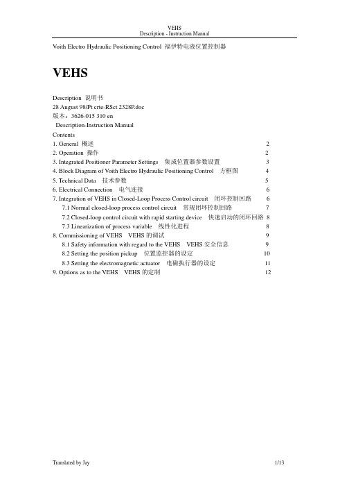
Voith Electro Hydraulic Positioning Control 福伊特电液位置控制器VEHSDescription 说明书28 August 98/Pt crte-RSct 2328P.doc版本:3626-015 310 enDescription-Instruction ManualContents1. General 概述 22. Operation 操作 23. Integrated Positioner Parameter Settings 集成位置器参数设置 34. Block Diagram of Voith Electro Hydraulic Positioning Control 方框图 45. Technical Data 技术参数 56. Electrical Connection 电气连接 67. Integration of VEHS in Closed-Loop Process Control circuit 闭环控制回路 67.1 Normal closed-loop process control circuit 常规闭环控制回路77.2 Closed-loop control circuit with rapid starting device 快速启动的闭环回路87.3 Linearization of process variable 线性化进程88. Commissioning of VEHS VEHS的调试98.1 Safety information with regard to the VEHS VEHS安全信息98.2 Setting the position pickup 位置监控器的设定108.3 Setting the electromagnetic actuator 电磁执行器的设定119. Options as to the VEHS VEHS的定制121. Gerneral 概述The Voith Electro Hydraulic Positioning Control serves to provide an exact and continuous positioning. The VEHS is used for positioning the scoop tube for geared variable speed couplings and for positioning the guide vane for torque converters. the VEHS is a compact unit consisting of an electromagnetic actuator, a double-acting cylinder and the electronic position pickup.福伊特电液位置控制器能准确并连续的控制液力耦合器的勺管或者变矩器的导叶位置。
- 1、下载文档前请自行甄别文档内容的完整性,平台不提供额外的编辑、内容补充、找答案等附加服务。
- 2、"仅部分预览"的文档,不可在线预览部分如存在完整性等问题,可反馈申请退款(可完整预览的文档不适用该条件!)。
- 3、如文档侵犯您的权益,请联系客服反馈,我们会尽快为您处理(人工客服工作时间:9:00-18:30)。
Voith TurboCouplingswith constantfilling12As an expert in difficult applications in pow er transmission Voith continues to meet the increasing requirements through innovative product design and performance.Constant-fill Voith Turbo Couplings are used w ith electric motors in a wide range of applications, especially w hen highest pow ers, economy and reliability are required.The Voith Turbo Coupling with its in-herent hydrodynamic advantages has proven itself in millions of applications worldwide:I smooth acceleration of the largest massesI suitable for economically priced squirrel cage motorsI load free start-up and run-up of motorI no motor modification requiredI torque control during start-upI effective shock-absorptionI overload protection for motor and machineI load compensation for multi-motor drives.3cal contact between power-transmit-ting parts.The coupling contains a constant q uantity of operating fluid, usually mineral oil.The torq ue transmitted by the drive motor is converted into kinetic energy of the operating fluid in the pump wheel to which the motor is connect-ed. In the turbine wheel, this kinetic energy is converted back into me-chanical energy. When it comes to the function of the coupling, three modes are to be noted:Föttingers concept –Design and functionStartingThe pump-wheel acceler-ates the operating fluid as revolutions in the drive-motor increase, so that a circular flow of fluid is created in the working chamber. The entire blad-ed surface of the turbine wheel is impacted and thus set in motion through kinetic energy. The torque development during the starting procedure is indi-cated by the characteristic curve of the coupling.StationaryAll operating fluid in the coupling is staticOperation at Normal RatingOwing to the minimal dif-ference in speed between the pump and turbine wheel, a constant flow is achieved in the coupling.Only the demand torque from the machine is trans-mitted.Through skillful coordina-tion of compensating chambers, such as the delay chamber and the an-nular chamber shell, the starting performance of the Turbo Coupling can be reg-ulated (see characteristic curves on page 4).A suitable coupling for any drive Essential performance factors for a Arraycoupling are the power and speed ofthe drive motor.Having established the nominalpower and speed required, the dia-gram on the right enables determina-tion of the appropriate size of thecoupling.Different conditions require differentstarting procedures (characteristiccurve) for the coupling. Important cri-teria in this respect are the mass mo-ment of inertia, torque limitation andfrequency of start-ups.In the table below different types ofcouplings and their starting conditionscan be compared.Typ TTyp TVTyp TVVTyp TVVS45Turbo Coupling Type T is the basic version of c onstant-fill c ouplings,onsisting of pump wheel, turbine wheel and outer shell.A further range has been c reated by the addition of other parts to this basic type.The turbo c oupling is normallymounted on the mac hine shaft orgearbox shaft to be driven (outer wheel drive). In order to c ompensate for any slight installation inaccuracies,a flexible connecting coupling is usedto join c oupling and input shaft. Op-tional designs are available for mountarrangements whic h are radially re-moveable without disturbing motor and reducer alignment.Installation of this type of coupling is re ommended when vibration and overload protec tion are required for motor and machine; they may also be used for simpler transmission systems in the lower performanc e range.The basic type –Turbo Coupling ”Type T”Applications–Bucket-wheel equipment –Excavators–Mixing, kneading and stirring machines6This version features a ”delay-fill chamb er“ which is flange-connected to the outer wheel of the coupling (Type TV). At stand-still, a proportion of the working fluid lies in this cham-b er, thus reducing the volume in the working chamb er. Hence on motor start-up, a reduced coupling torque is transmitted, simultaneously providing an unloaded motor start. After the motor has run up, the working fluid flows from the delay-fill chamber into the working chamber which smoothly accelerates the driven machine up to its operating speed.Furthermore, if the application so demands, the delay-fill chamb er can b e further enlarged (Type TVV), thus enhancing its effects and further re-ducing the coupling torque on motor start, as well as resulting in even longer and smoother start up of the driven machine.In certain cases, the function of the delay chamb er can b e additionally improved through centrifugally con-trolled valves (Type TVF) or through hydrodynamic refill (Type TVY).Smoother start up –Turbo Coupling ”Type TV” and ”TVV”Applications:– Belt conveyors – Chain conveyors– Centrifuges, decanters – Tube Mills– High-inertia machinesA further Voith development is the an-nular-chamber shell additional to theenlarged delay chamber (Type TVVS).The additional chamber in thecoupling shell enables f urther reduc-tion of the starting torque. During theinitial rotations of the start-up proce-dure, centrifugalforces cause theouter chamber of the coupling to becompletely f illed with operating f luidfrom the bladed area.In comparison with couplings withoutannular chamber, filling of the bladedarea of a TVVS Coupling is consider-ably reduced, which, in turn, reducesthe torque transmitted during motorrun-up.The increase in torque then f ollowsthrough gradual emptying of the fluidfrom the delay chamber into the blad-ed area.The starting procedure can be adapt-ed to the requirements of the applica-tion by adjustable nozzle screws.This new concept f or couplings wasdesigned especially for conveyor beltdrives. Through the gradual build upof torque an automatic adaptation tobelt load conditions is achieved.The innovative one –Turbo Coupling ”Type TVVS”Application– Belt conveyors8The ”v“-be lt, timing be lt, or flat be lt pulley which is flanged to the bearing cover allows various transmission ra-tios to be accommodated. If required,the pulley may be easily exchanged.TRI and TVRI type Turbo Couplings are normally installe d on the motor shaft in an ove rhung position. The belt force is supported by a bearing in the be aring cove r on the coupling hub.TRI type Turbo Couplings can be in-stalled both as starting aid and over-load protection. Type TVRI with addi-tional de lay chambe r is re comme nd-ed if a particularly smooth start-up is required.For pulley drives –Turbo Coupling ”Type TRI/TVRI”Applications– Centrifuges and decanters – Fans – Mixers – Crushers9MTS mechanical thermal switches As protection against overheating, fu-sible plugs are standard.In order to avoid los s of operating fluid through thermal overload, a me-chanical thermal switch – MTS – can be added.On achieving the res pons e tempera-ture, the element activate a pin which then operates a switch.Depending on the type of circuit, the signal can be used either as an alarm or to switch off the motor.The circuit element has to be re-placed after activation.Monitoring devices and accessoriesBTS – Non-contact thermal switch Monitoring of coupling temperatures take splace without any contact.After activation of the s witch, no re-placement of the element is required.It is ready for us e as s oon as the coupling has cooled down.The s ignal can be us ed either as an alarm or to switch off the motor.In s ome cas es BTS can be us ed as speed monitor.Fitting and dismantling tool Required for profes s ional, s afe fitting and dismantling.As well as the mechanical fitting and dismantling tool, a hydraulic pressure device is available.Sight glassBy fitting a sight glass, the fluid level in the coupling can be easily checkedwithout opening the coupling.10In order to prov ide solutions for an ev er greater v ariety of applications,our engineers and technicians hav e dev eloped additional types of con-stant-fill couplings.Turbo Coupling with solid shaft and primary coupling flangeThe coupling is fitted rigid to the motor shaft ov er a primary coupling flange. The weight of the coupling is thus carried by the motor shaft and the load on the drive shaft is relieved.An elastic connecting coupling is re-quired between the solid shaft on the output side and the driven shaft.By using a specially designed flexible connecting coupling it is possible to fit or dismantle the coupling radially without moving motor or gears.For special applications –Additional typesTurbo Coupling with brake flange For use with a breaking system, the turbo coupling can be equipped with an additional brake flange to which a brake-drum or brake-disc is fitted.Turbo Coupling with twin circuit “Type DT”This coupling has two co-axial work circuits operating in parallel.By means of a double circuit the out-put of the same size coupling is effec-tively doubled.The properties, s uch as s tarting and overload protection are comparable with thos e of bas ic Type T without delay chamber.For available sizes of Turbo Coupling Type DT see performance characteri-stic diagram on page 4.Pulley-type couplingwithout bearing cover Type TRIThis type is ideally suited for particu-larly small belt discs.The pulley with integral bearing isflanged directly to the coupling shell.Subs equent replacement of the beltdisc would be costly.Turbo Coupling with overhungpulley installation – Type TRIn this simplified version of the pulleycoupling, the pulley is fitted to thecoupling shell in an overhung fashion.Turbo Coupling TR is an economicals olution for applications in the lowerpower range.11G R O U P O F C O M PA N I E SC r 128 eVoith Turbo GmbH & Co. KG Start-up Components P.O. Box 1555D-74555 Crailsheim Phone (07951) 32-0Fax (07951) 32-650http://www.voith.deE-Mail: anfahrkomponenten@voith.deModern drive concepts demand state-of-the-art technology, hence Voith drives are present where exacting per-formance is demanded.Decades of experience in the field of hydrodynamics, continuous research and development, state-of-the-art pro-duction technology and the Voith know-how guarantee the quality of our product and keep it at the fore-front of technological development.Our quality is certified under the code DIN ISO 9001.Our engineers with their specialized product knowledge are at your dispo-sal to provide the optimum drive solu-tion for your applications.Marketing companies and sales agen-cies in every continent ensure close contact with our customers and guar-antee rapid service.ESPRIT, EXCELLENCE and EFFIZIENZ together symbolize the factors through which concepts are born and products created within the Voith Group.ESPR IT – researching and developing in the service of the customer.EXCELLENCE – staying ahead of the field.EFFIZIENZ – transforming individual achievement into corporate success.For our customers. For our staff. For our company.Competence inhydrodynamic drivetechnology。