ZT160-200-250-275零件手册1998
力士乐液压油缸CDL2重载型rc17326_2013-06

项目设计软件 Interactive Catalog System
在线
/ics
内容
特点 订货代码 项目设计软件 ICS(交互式目录系统) 技术数据 直径,面积,力,流量 公差 总览:安装类型 单位 尺寸: ▶ 安装类型 MP5 ▶ 安装类型 MF3 ▶ 安装类型 MT4 ▶ 安装类型 M00 ▶ 铰接吊环头 CGKL ▶ 铰接吊环头 CGKD ▶ 耳轴支架 CLTB ▶ 吊头支架 CLCA ▶ 吊头支架 CLCD 弯曲计算 允许的行程长度:MP5;MF3;MT4 总览:单独组件 密封套件 液压缸重量
...
C 3) D 4) 1X
B
1
管路连接/缸底位置
11 对着活塞杆端看
1
1
活塞杆款式 12 镀硬铬
活塞杆端 13 螺纹 带已安装的铰接吊环头 CGKD 的活塞杆端 H 带铰接吊环头,不可拆卸 内螺纹 带已安装的铰接吊环头 CGKL 的活塞杆端
终端位置缓冲 14 不带终端位置缓冲
密封件设计 15 标准密封系统(适用于矿物油 HL,HLP) 标准密封系统 FKM(适用于磷酸酯 HFDR)
活塞杆直径 ØMM mm
公称压力
160 bar 250 bar
14
–
18
–
22
–
–
25
28
–
–
32
36
–
–
40
45
–
–
50
56
–
–
63
70
–
–
80
–
100
–
125
面积比 ϕ
A1/A3
1,46 1,46 1,43 1,64 1,46 1,69 1,49 1,68 1,46 1,64 1,46 1,66 1,46 1,69 1,64 1,64
海尔 CQG-E50BU1 50升嵌入式蒸烤炸一体机 使用说明书

安装指导
蒸烤炸一体机整机尺寸
#
"᭧
)
$'
(
ᮇ᭧
产品尺寸
A 产品总高度 B 产品总宽度 C 产品总深度(不包括手柄) D 底板高度 E 底板宽度 F 底板深度 G 蒸烤炸一体机支架和控制面板深度 ( = 底板正面和蒸烤炸一体机门正面之间的距离) H 蒸烤炸一体机门全开深度 ( 从控制面板正面开始算起)
4
安装指导
安装前检查
安装前请仔细阅读说明书的安装指导部分。 打开包装,将包装材料妥善放置。 确保安装蒸烤炸一体机所用的橱柜材料及粘合剂能耐 95℃以上的温度。 确保用于固定蒸烤炸一体机的橱柜单元的底部能承受 60kg 以上的重量。 如果将蒸烤炸一体机安装在橱柜拐角附近,为避免橱柜过热,请保持蒸烤炸一体机 与拐角另一侧的橱柜距离在 90mm 以上。 建议将连接蒸烤炸一体机的插座装在与安装蒸烤炸一体机的橱柜单元相邻橱柜内, 以便于更换灯泡等操作时将蒸烤炸一体机电源断开。 若本产品安装在灶具下方,灶具燃气管必须采用波纹管且有效固定,确保不会触碰 到本产品。 若安装在灶具下方,确保灶具使用过程中没有水或杂物掉(漏)入橱柜中。 若安装在灶具下方,本产品顶盖不得影响下进风式灶具风门开关调节功能,推荐灶 具底盘与本产品顶盖间距≥ 8cm。 若安装在灶具下方,橱柜通风条件参考灶具安装标准且本产品不能遮挡通风孔。 如不符合以上要求,需整改安装环境,否则可能会造成财产损失或人身伤害。 本产品为前置排气,若安装在灶具下方,用户会感受到一定的热气或热蒸汽,灶具 玻璃上可能会有冷凝水产生,这是正常现象。
警告
插座位置在离蒸烤炸一体机背部 0.5m 内。 插座需能提供 16A 及以上的电流。
注意
使用过程中本设备的部件可能会发烫。应确保儿童在靠近设备时有人监护。 为了保护环境以及您的安全,请注意以下问题 :
八特尔控制系统3件通常口径球值安装与维护手册说明书

Contents1.SCOPE (2)2.INSTALLATION (2)3.VALVE OPERATION (3)4.DISASSEMBLY (3)5.ASSEMBLY (4)6.REPAIR KITS (5)7.BILL OF MATERIALS (6)1.SCOPE1.1. CAUTION1.1.1. F or your safety, read this manual before installation or service.1.1.2. B efore installing or servicing, please ensure the line pressure has been relieved and any hazardous fluidshave been drained or purged from the system.1.1.3. E nsure that all Lockout and Tagout procedures for the system have been properly implemented.1.2. USE1.2.1. M aximum results and long life of valves can be maintained under normal working conditions and accordingwith pressure/temperature ratings and corrosion data chart.2.INSTALLATION2.1. GENERAL INFORMATION FOR INSTALLATION2.1.1. T he valve can be installed in any position on the pipeline.2.1.2. B efore installation of the valve, the pipe must be flushed clean of dirt, burrs, and welding residue, or theseats and ball surface will be damaged. The pipe must be free from tension and in proper alignment. Checkto ensure that all connections are free from defects.2.2. INSTALLATION OF THREADED VALVES2.2.1. U se conventional sealant, such as hemp core, Teflon, etc. on threads. Apply wrench only on the hexagonof the valve ends. Tightening by using the valve body or lever can seriously damage the valve. In someapplication, screwed valves are back welded on site. These valves must be treated as per instructions forthe weld end valves before back welding.2.3. INSTALLATION OF WELDED ENDS2.3.1. T ack weld the valve on the pipe in four points on both end caps.2.3.2. W ith the valve in the open position, (lever to be parallel to the axis of the pipe), remove all the body boltsexcept one. Loosen the nut on the remaining bolt. Swing the body outside the pipe. Finish welding bothend caps on the pipe.2.3.3.2.3.4. W hen cooled down, clean both end caps and body surface.2.3.5. S wing the body back in position and replace the bolts. Tighten all nuts slightly. This operation is veryimportant to keep the body and end caps perfectly parallel, thus preventing distortion of end caps. Tightenbody bolts evenly (see section 5.5). Make sure that maximum tightening torque is observed. Check properoperation of the valve.3.VALVE OPERATION3.1.MANUAL3.1.1.HANDLE3.1.1.1.To OPEN the valve, turn the handle counterclockwise until the handle is parallel with the pipeline and the handlehas contacted the handle stop.3.1.1.2.To CLOSE the valve, turn the handle clockwise until the handle is perpendicular with the pipeline and the handlehas contacted the handle stop.3.1.1.3.A handle lock is incorporated into the handle. To use, slide the lock into the mounting pad, in the full open orfull closed position. Insert an appropriate size lock or hasp into the handle. If it can be performed safely, try toturn the handle to ensure that the valve has been locked properly.3.1.2.GEAR3.1.2.1.To OPEN the valve, turn the handle wheel counterclockwise. The indicator will be pointing to the open positionand stop rotating when fully opened. The flow can be adjusted by stopping the indicator anywhere between openand close.3.1.2.2.To CLOSE the valve, turn the hand wheel clockwise. The indicator will be pointing to the close position and thehandwheel will stop rotating when fully closed. The flow can be adjusted by stopping the indicator anywherebetween open and close.3.2.AUTOMATED3.2.1.A-T Controls 83/8R Series Ball Valves can be mounted with quarter turn actuators. Valves with actuators shall bechecked for proper valve stem alignment. Angular or linear misalignment may result in high operational torque andunnecessary wear on the valve stem. See the actuator IOM for information on operating the actuator.4.DISASSEMBLYWARNINGCAUTION, FLUIDS CAN BE TRAPPED IN THE BODY OF THE VALVE, POSSIBLY UNDER HIGH PRESSURE. FOR YOUR SAFEY, IT IS IMPORTANT THAT PRECAUTIONS ARETAKEN BEFORE REMOVAL OF THE VALVE FROM THE LINE OR ANY DISASSEMBLY.4.1.Remove actuator or gear if equipped.4.2.Care should be taken to not damage the surface finish of the valve components.4.3.Remove the ends (2) from the body (1) by removing the body bolts (17) and body nuts (18).4.4.Remove the seat (4) and body gaskets (5) from both sides of the body (1). Once removed, with the valve in the fully closedposition, the ball (3) should slide freely out of the body (1).4.5.If equipped, remove the handle nut (13), handle (14), and the handle stop assembly items (16).4.6.While holding the stem (6) stationary, remove the packing nut (21). Once removed, the locking saddle (12), Bellevillewashers (11), and the packing bushing (9) should be free to remove.4.7.While holding the bottom of the stem (6), push the stem (6) through the inside of the valve body (1).4.8.Remove the packing set (8) and the stem seal (7).4.9.Inspect all components for damage and, if necessary, clean or replace.5.ASSEMBLY5.1.Care should be taken to not damage the surface finish of the valve components.5.2.Place stem seal (7) on the stem (6) and install it by going through the body (2). Insert V-style packing set (8) over stem (6),with the V pointing away from the valve (see Bill of Materials for correct orientation).5.3.Install the packing gland (10), the Belleville washers (11), the locking saddle (12), and the packing nut (21). While holdingthe stem (6), tighten the packing nut (21) to the torque listen in the Fastener Torque Chart. Tighten further if needed in order to be able to place the locking saddle (12) over the packing nut (21).5.4.Ensure the stem (6) is in the closed position with the body tang parallel with the flow of the valve. Insert a seat (4) and bodygasket (5) in one side of the body (1). Carefully slide the ball (3) into the body (1) and insert the other seat (4) and body gasket (5).5.5.Assemble ends (2) onto body (1). Insert all body bolts (17) and nuts (18) into valve and tighten to finger tight, making surethat the ends (2) are flat against the body (1). Tighten all body bolts (on both side for valves 2-1/2” thru 4”) from the nut(18) side (if equipped) in a star pattern to 50% of the final torque shown in the Fastener Torque Chart. Using the handle (14)or an adjustable wrench, cycle the valve 3 times. Tighten all body bolts (17) to the final torque in a star pattern. Check each body bolt (17) torque and tighten if needed a final time. It is acceptable for the torque to relax slightly over time due to relaxation of the polymer components, but the valve will still seal properly. If leakage is detected, repeat the steps for tightening the body bolts (17).5.6.If required, assemble the locking device (19), handle stop (16), handle (14), and the handle nut (13).6.REPAIR KITSRepair kits are available to replace all soft goods. See Bill of Materials for components that are included in the repair kits.7.BILL OF MATERIALSA-T Controls product, when properly selected, is designed to perform its intended function safely during its useful life. However, the purchaser or user of A-T Controls products should be aware that A-T Controls products might be used in numerous applications under a wide variety of industrial service conditions. Although A-T Controls can provide general guidelines, it cannot provide specific data and warnings for all possible applications. The purchaser / user must therefore assume the ultimate responsibility for the proper sizing and selection, installation, operation, and maintenance of A-T Controls products. The user should read and understand the installation operation maintenance (IOM) instructions included with the product and train its employees and contractors in the safe use of A-T Controls products in connection with the specific application.While the information and specifications contained in this literature are believed to be accurate, they are supplied for informative purposes only. Because A-T Controls is continually improving and upgrading its product design, the specifications, dimensions and information contained in this literature are subject to change without notice. Should any question arise concerning these specifications, the purchaser/user should contact A-T Controls.For product specifications go to https:///Downloads/A-T Controls, Inc. • 9955 International Boulevard, Cincinnati, OH 45246 • Phone: (513) 530-5175 • Fax: (513) 247-5462 • 。
Powertec i250C i320C电气方案备用零件说明说明书

Spare Parts - Electrical Schematic Spare Parts - Electrical Schematic1 IM3070 09/2018 REV03POWERTEC i250C STANDARD POWERTEC i250C ADVANCED POWERTEC i320C STANDARDPOWERTEC i320C ADVANCEDSpare Parts (2)Figure A: Powertec i250C/i320C STD/ADV Machine Assembly .................................................................................. 2 Figure B: Powertec i250C/i320C STD/ADV Inside Machine Assembly ....................................................................... 4 Figure C: Powertec i250C/i320C STD/ADV Wire Drive Assembly ............................................................................... 5 Figure D: Powertec i250C/i320C STD Front Assembly ................................................................................................ 6 Figure E: Powertec i250C/i320C ADV Front Assembly (6)Electrical Schematic (8)Lincoln Electric Bester Sp. z o.o.ul. Jana III Sobieskiego 19A, 58-263 Bielawa, Polandwww.lincolnelectric.euSpare Parts - Electrical Schematic Spare Parts - Electrical Schematic2 Spare PartsSP50430, SP50431, SP50432, SP50433 REV03ASSEMBLY PAGE NAMEP o w e r t e c M a c h i n e A s s e m b l yM a c h i n e F r o n t A s s e m b l y W i r e D r i v e A s s e m b l y & E u r o S o c k e t A s s e m b l yP o w e r t e c i 250C /i 320C S T D F r o n t A s s e m b l y P o w e r t e c i 250C /i 320C A D V F r o n t A s s e m b l y M i s c e l l a n e o u s I t e m s CODE NO.: K NO.: FIGURE NO.:A B C D E - 50430POWERTEC i250C STANDARD 1 1 1 1 - 1 50431 K14157-2 POWERTEC i250C ADVANCED 2 2 2 - 2 2 50432 K14158-1 POWERTEC i320C STANDARD 3 3 3 3 - 3 50433 K14158-2 POWERTEC i320C ADVANCED 444-44Figure A: Powertec i250C/i320C STD/ADV Machine AssemblyItem Description Part Number QTY 1 2 3 4 5 6 CABLE GRD-300A-50-5M 1 x x x x1 WELDING2 SIDE PANEL KIT R-1019-486-1R 1 x x x x3 COVERKIT R-3019-455-1/02R 1 x x x x4 HANDLE R-0010-292-1R 1 x x x x5 BASE, PARTITION, SHELF KIT R-3019-426-1R 1 x x x x6 SIDE COVER KIT R-0010-623-1R 1 x x x x7 FRONT AND REAR PANEL KIT R-8040-387-1R 1 x x x x8 LOCK 0654-610-004R 2 x x x xHINGE 0654-610-007R 2 x x x x9 LEAF10 MAIN INPUT CORD R-5041-497-1R 1 x x x x11 WHEELS 1029-660-127R 2 x x x x12 WHEELS 1029-660-250R 2 x x x xSpare Parts - Electrical Schematic Spare Parts - Electrical Schematic3Spare Parts - Electrical SchematicSpare Parts - Electrical Schematic4Figure B: Powertec i250C/i320C STD/ADV Inside Machine AssemblyItem DescriptionPart NumberQTY 1 2 3 4 5 6 13 TRANSFORMER AND CHOKE R-8040-382-2R 1 x x x x 14 INVERTER BOARD R-6042-079-1R 1 x x x x 15 HALL SENSOR W4900004R 1 x x x x 16 FAN W66X1369R 2 x x x x 17 INPUT FILTER Y051-1R1 x x x x 18 SOLENOID 0972-423-040R 1 x x x x 19 CABLE RELIEF1361-599-674R 1 x x x x 20FUSE SOCKET 1158-632-032R 1 x x x x FUSE 1A 400V 1158-660-003R 1 x x x x 21 PC BOARD R-6042-081-1R 1 x x x x 22 WIRE SPOOL HUB 0744-000-335R 1 x x x x 23 PLASTIC NUT 0744-000-336R 1 x x x x 24 USB SOCKET 1158-641-061R 1 - x - x 25 SWITCH1115-280-004R 1 x x x x 26 THREE PHASE BRIDGE1156-112-206R 1 x x x x 27CONTROL BOARD R-6042-082-2R 1 x - - - CONTROL BOARD R-6042-082-1R 1 - x - - CONTROL BOARD R-6042-080-2R 1 - - x - CONTROL BOARD R-6042-080-1R 1 - - - x 28 OUTPUT BRIDGE R-8040-388-1R 1 x x x x 29 LED MODULE R-5041-508-1R 2x x x xFigure C: Powertec i250C/i320C STD/ADV Wire Drive AssemblyItem Description Part Number QTY 1 2 3 4 5 6 30 WIRE DRIVE MOTOR 1111-722-048R 1 x x x x31 COMPLETE FEED PLATE ASSEMBLY(INCLUDES 1.0/1.2 MM DRIVE ROLLS ANDWIRE GUIDE KIT)0744-000-009R 1 x x x xSpare Parts - Electrical Schematic Spare Parts - Electrical Schematic5Spare Parts - Electrical SchematicSpare Parts - Electrical Schematic6Figure D: Powertec i250C/i320C STD Front AssemblyFigure E: Powertec i250C/i320C ADV Front AssemblyItem Description Part Number QTY 1 2 3 4 5 632 DISPLAY FRONT PANEL KIT R-0010-619-2R 1 x - x -33 USER INTERFACE PCB R-6042-078-1R 1 x - x -34 KNOB 9SM22778-2 2 x - x -35 BUTTON 9SS23055 2 x - x - 1 - x - x36 MAIN SWITCH 1115-270-022R 1 x x x x37 EURO SLEEVE C-1891-006-1R 1 x x x x38 SOCKET W7690350 R 2 x x x x39 PCB R-6042-077-1R 1 - x - x40 DISPLAY FRONT PANEL KIT R-0010-618-2R 1 - x - x41 LCD 0942-177-002R 1 - x - x42 KNOB 9SM22778-3 2 - x - xMiscelaneous Items (not shown in figure A, B, C, D, E)Item Description Part Number QTY 1 2 3 4 5 643 HARNESSES KIT R-5041-494-1R 1 x x x xSpare Parts - Electrical Schematic Spare Parts - Electrical Schematic7Electrical SchematicSpare Parts - Electrical Schematic Spare Parts - Electrical Schematic8234Spare Parts - Electrical Schematic Spare Parts - Electrical Schematic9。
GK1C常用配件解析
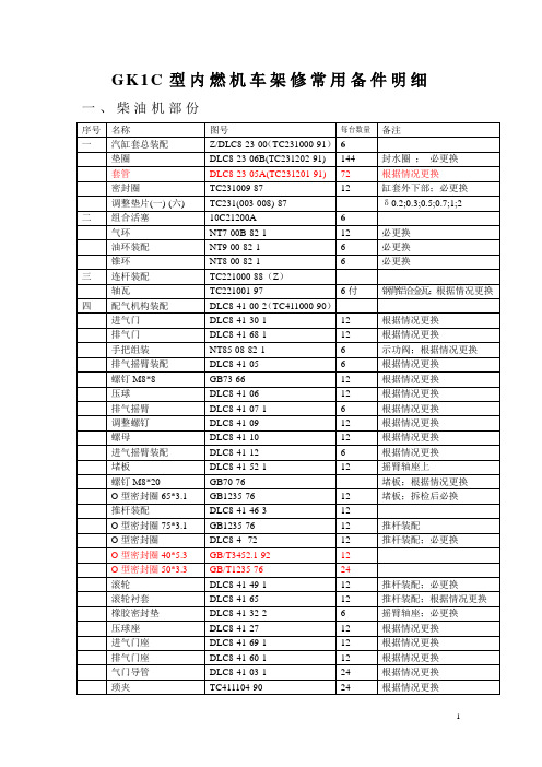
GB70-76
堵板;根据情况更换
O型密封圈65*3.1
GB1235-76
12
堵板;拆检后必换
推杆装配
DLC8-41-46-3
12
O型密封圈75*3.1
GB1235-76
12
推杆装配
O型密封圈
DLC8-4--72
12
推杆装配;必更换
O型密封圈40*5.3
GB/T3452.1-92
12
O型密封圈50*3.3
ZJC2-15-00-000
垫片(δ1.5石棉板)
ZJC2-15-00-004
1
端盖;必更换
垫片(δ1.5石棉板)
ZJC2-15-00-009
1
密封盖;必更换
垫片(δ1.5石棉板)
ZJC2-15-00-013
1
箱体;必更换
垫片(δ1.5石棉板)
ZJC2-15-00-007
2
水泵孔;必更换
垫片(δ1.5石棉板)
ZJJ8-32-04-000
2
液力换向控制阀
(阀体上下平面处)
O型密封圈16*2.65G
GB/T3452.0-1992
2
换向控制阀
上垫
ZJJ25-33-04-006
1
换向控制阀
下垫
ZJJ25-33-04-013
1
换向控制阀
垫板
ZJJ25-33-04-012
1
换向控制阀
6
O型密封圈16×2.4
GB1235-76
排气支管垫(一)
ZJN10-71-00-010
7
与总管连接;必更换
排气支管垫(二)
DLC8-71-03A-1(Z)
配件装配通用技术条件

GZSW/技北京国中生物科技有限公司配件装配通用技术条件(初稿)审批:审核:编制:目录1、范围 ........................................ 错误!未定义书签。
2、引用标准 .................................... 错误!未定义书签。
3、基本要求 .................................... 错误!未定义书签。
4、各种连接方法的要求 .......................... 错误!未定义书签。
螺钉、螺栓连接............................. 错误!未定义书签。
销连接...................................... 错误!未定义书签。
键连接..................................... 错误!未定义书签。
过盈连接.................................... 错误!未定义书签。
5、典型部件装配要求 ............................ 错误!未定义书签。
滚动轴承的装配.............................. 错误!未定义书签。
联轴器的装配................................ 错误!未定义书签。
齿轮的装配................................. 错误!未定义书签。
链轮、链条的装配........................... 错误!未定义书签。
带与带轮的装配.............................. 错误!未定义书签。
润滑系统的装配.............................. 错误!未定义书签。
气动系统的装配............................. 错误!未定义书签。
ML110-ML160零件手册

MLG-110G MLG-132G MLG-160G PARTS MANUAL
零件手册
在安装或第一次起动压缩机之前,请仔细阅读本手册,清楚了解 压缩机的有关知识以及操作维修的注意事项。 请把本手册与机器一起移交使用者。 本技术手册内有重要的安全信息,应一直与压缩机一起保存。
ATC32201
第一章 引言
SECTION 1 INTRODUCTION
如何使用本零件手册 1.参考目录,找出所需章节。 2.翻到所需章节,并参照零件图的目录,找到该零件所属系统的所在页。 3.按序号辨别出该零件在图上的位置。 定购零件
HOW TO USE THIS PARTS MANUAL
1. Refer to the index and find the Section. 2. Turn to the Section and refer to the table of Connects to locate the
序号 No.
8 9 10 11 12 13 14 15 16 17 18 19 19A 20
零件号 CPN
ATC20080 99271033 S1111640 35255819
—— 39167150 39326483 S1111640 92539311 39253992 95239929 39112362 22060701 42870550 95022125 95022125 H0059310
MOTOR,GEARCASE AND GEAR SET
数量
说明
QTY. 1 6 1 1 1 1 1 1 1 1 2 1 1 14 1 1 1
desired illustrations. 3. Locate the part on the illustration by visual identification and the
阿特拉斯空压机(INSTRUCTION)
GA90 - GA110 - GA132 - GA160 - GA200 - GA250 - GA315 GA90 W - GA110 W - GA132 W - GA160 W - GA200 W GA250 W - GA315 W
使用说明书
重要提示
1. 对GA/GA W 90到 160, 从系列号 AIF-078 300开始使用 . 2. 对GA/GA W 200 到 315, 从系列号 AIF-078 302开始使用 . 3. 该书必须和 " GA-GR-ZA-ZE-ZR-ZT Elektronikon® 电脑控制器使用手册”联合使用。
1.3 Elektronikon® 控制系统 . . . . . . . . . . . . . . . . . . . . . . . 10 1.3.1 自动控制空压机 . . . . . . . . . . . . . . . . . . . . . . . 10 1.3.2 保护空压机 . . . . . . . . . . . . . . . . . . . . . . . . . . . 10 1.3.3 维修报警 . . . . . . . . . . . . . . . . . . . . . . . . . . . . . 10 1.3.4 断电后自动重新起动 . . . . . . . . . . . . . . . . . . . 11 1.3.5 允许起动 . . . . . . . . . . . . . . . . . . . . . . . . . . . . . 11
2 安 装 . . . . . . . . . . . . . . . . . . . . . . . . . . . . . . . . . . . . . . . . . . . 15 2.1 尺寸图 . . . . . . . . . . . . . . . . . . . . . . . . . . . . . . . . . . . . . 15 2.2 安装建议 . . . . . . . . . . . . . . . . . . . . . . . . . . . . . . . . . . . 21 2.3 电缆的规格 . . . . . . . . . . . . . . . . . . . . . . . . . . . . . . . . . 27 2.4 图标 . . . . . . . . . . . . . . . . . . . . . . . . . . . . . . . . . . . . . . . 28 2.5 冷却水的要求 . . . . . . . . . . . . . . . . . . . . . . . . . . . . . . 28 2.5.1 冷却系统的类型 . . . . . . . . . . . . . . . . . . . . . . . 28 2.5.2 冷却水的参数 . . . . . . . . . . . . . . . . . . . . . . . . . 29