太航流量计安装使用说明书
插入式流量计使用说明书
一、简介HHCD系列电磁流量计的产品性能符合行业标准JB/T9248-1999。
在出厂前必须通过多个技术指标的严格检验。
流量计到货后,请您务必检查其外观,确认运输过程中仪表有无损坏。
请参考本章内容检查仪表附件。
HHCD插入式电磁流量计是在管道式电磁流量计的基础上发展起来的一种新型流体流量仪表。
它在保留管道式电磁流量计优点的基础上,针对管道式电磁流量计在大管道上安装困难,费用大等缺陷,根据尼库接磁(NIKURADS)原理,用电磁方法通过测量流体的平均流速,从而获得流体的体积流量。
特别是采用带压开孔、带压安装技术后,插入式电磁流量计可在不停车(水)的情况下安装,也可在铸铁管道,水泥管道上安装。
插入式电磁流量计的研制成功,为流体流量的检测提供了一种新的手段。
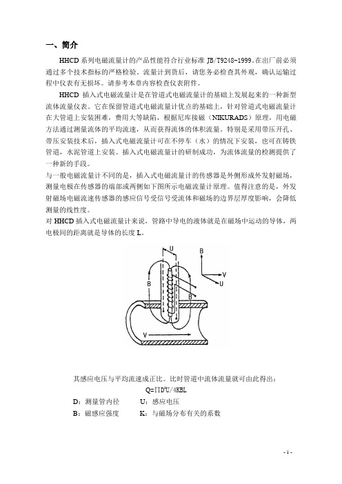
与一般电磁流量计不同的是,插入式电磁流量计的传感器是外侧形成外发射磁场,测量电极在传感器的端部或两侧如下图所示电磁流量计原理。
值得注意的是,外发射磁场电磁流速传感器的感应信号受信号受流体和磁场的边界层厚度影响,会降低测量的线性度。
对HHCD插入式电磁流量计来说,管路中导电的液体就是在磁场中运动的导体,两电极间的距离就是导体的长度L。
其感应电压与平均流速成正比。
比时管道中流体流量就可由此得出:Q=∏D2U/4KBLD:测量管内径U:感应电压B:磁感应强度K:与磁场分布有关的系数1.1、检查型号和规格型号和技术规格可从电磁流量计铭牌、出厂校验单上查到,检查一下该仪表型号和技术规格是否与所定仪表型号和技术规格一致。
如果产品出现质量问题或者您在使用仪表中遇到问题需要和我公司联系时,请说明仪表的型号规格和编号,便于我们解决问题。
1.2、装箱单流量计到货时,应确认下列物件是否装箱传感器(一台)转换器(一台)(仅限分体式)使用说明书(一份)校验单(一份)合格证(一份)电缆(仅限分体式,用户定购长度)外配法兰(用户定购时配备)螺栓螺帽(用户定购时配备)密封胶(用户需现场密封时配备,一般情况出厂已密封)防爆合格证(仅限防爆型产品)1.3、贮存注意事项产品到货后,如果仪表需要存放一段较长的时间,特别要注意以下几点:1、用原包装箱好仪表,尽量保持与发运出厂前状态一样。
插入式电磁流量计安装使用说明书最新修改0

智能插入式电磁流量计ZHINENG CHARUSHI DIANCI LIULIANG JI安装使用说明书衢州五星自动化仪表有限公司目录一、插入式电磁流量计简介1.1产品概述 (2)1.2测量原理 (2)1.3测量系统的组成 (4)二、主要技术参数 52.1智能型转换器的技术参数 (5)2.2传感器技术参数 (5)三、仪表选型(6)3.1流量计型号命名 (6)3.2流量计的结构及外形尺寸 (6)四、流量计的安装74.1传感器的安装方式 (7)4.2传感器的安装位臵的选择 (7)4.3传感器的安装方法及尺寸 (8)4.4传感器的接地 (9)五、转换器的接线和操作说明(9)5.1 外形及传感器的连接方式 (9)5.2 转换器的电气接线 (10)5.3 转换器操作面板的键盘定义与液晶显示 (11)5.4 转换器参数的设臵及操作 (11)5.4.1自动测量状态下的键功能 (12)5.4.2 参数设臵状态下各键功能 (12)5.4.3 参数设臵功能及功能键操作 (12)5.4.4 总量清零 (12)5.4.5 参数设臵菜单 (13)5.5 报警信息 (14)5.6 故障处理 (14)5.6.1 仪表无显示 (14)5.6.2 励磁报警 (14)5.6.3 空管报警 (15)5.6.4 测量的流量不准确 (15)一插入式电磁流量计简介1.1产品概述:电磁流量计是一种测量导电流体体积流量的感应式仪表。
本公司WXCDL型插入式电磁流量计是在管道式电磁流量计的基础上发展起来的一种新型流体流量仪表。
它在保留管道式电磁流量计优点的基础上,针对管道式电磁流量计在大管道上安装困难、费用大等缺陷,根据尼库拉磁(NIKURADS)原理,用电磁方法通过测量流体的平均流速,从而获得流体的体积流量。
特别是采用了带压开孔,带压安装技术后,插入式电磁流量计可在不停车(水)的情况下安装,也可在铸铁管、水泥管、PE管上安装。
插入式电磁流量计的研制成功,为流体流量的检测提供了一种新的手段。
流量仪表安装施工作业指导书
流量仪表安装施工作业指导书1.总则目的为了提高自动化仪表工程施工技术和治理水平,实施现行施工标准和工程质量检验评定标准,加强企业技术治理的根底工作,标准流量仪表工程施工工艺,确保工程质量和施工安全,特编制此作业指导书。
适用范围本作业指导书适用于工业和民用建筑工程流量取源部件和流量仪表安装工程的施工。
本作业指导书不适用于制造、贮存、使用爆炸物质的场所以及交通工具、矿井井下、气象等仪表安装工程。
编制依据本施工作业指导书编制所依据的标准:《自动化仪表工程施工及验收标准》GB50093-2023《自动化仪表安装工程质量检验评定标准》GBJ131-90《石油化工仪表工程施工技术规程》SH3521-1999《石油建设工程质量检验评定标准自动化仪表安装工程》SY4031-932.设备、材料要求仪表设备和工程材料的规格、型号、材质均必需符合设计要求。
仪表设备及其附件应配套齐全,完好无损。
焊接材料应符合《现场设备、工业管道焊接工程施工及验收标准》GB50236-98 和焊接材料手册中的有关规定。
3.施工工机具机具:电焊机、电钻、无齿锯、电锤、手砂轮等。
工具:扳手、螺丝刀、管刀、弯管器、手锯、压线钳等。
量具:900角尺、水平尺、钢板〔卷〕尺、线锤、万用表等。
4、作业条件设计图纸、文件齐全,已经过施工图纸会审。
流量仪表产品使用说明书齐全,并附有设备配套清单。
已经过施工技术交底和必要的安全技术培训。
在管道上直接安装的取源部件安装位置、方位及连接件形式核查取源部件接续安装仪表支架仪表出库制安检查仪表设备测量管道安装连接接与接线地吹与试扫压现场已具备流量仪表安装条件。
设计文件要求脱脂的仪表已经脱脂合格。
仪表已经过单体试验、校准。
5、施工操作施工程序主要工序的施工操作在管道上直接安装的取源部件的安装位置、方位、连接件形式及规格应符合设计文件或仪表产品说明书要求。
5.2.2流量取源部件上、下游直管段的最小长度应符合设计文件要求。
流量仪表安装和使用

2019/8/8
6
JLQ+TMCS
2019/8/8
7
体积修正
2019/8/8
量测的体积
V
体积修正运算
VN
F
8
体积修正的概念
量测的体积 = V
(由现场操作条件与计量仪表得)
标准立方米
现场操作 压力与温 度
2019/8/8
转换运算
20°C 101325 Pa
2019/8/8
28
可换孔板节流装置产品外形及结构
前测量管段
孔板阀
后测量管段
2019/8/8
29
技术参数
公称通径:50 mm ~ 800 mm。 孔板开孔直径不小于12.5mm,0.2 ≤ β ≤ 0.75 范
围之间。 取压形式:法兰取压。 量程比:10:1;15:1;120:1。 公称压力:1.6~6.4 MPa。 系统精度:1.0~2.0 %。
27
标准孔板流量计的适用条件
流体必须充满圆管和节流装置。 流体通过测量段的流动必须保持亚音速的、稳定的或紧随时间缓
慢变化的。 流体必须是单相流体或者可以认为是单相流体。 公称通径不小于50mm和不大于1200mm。 管道雷诺数不低于3150的场合。 可用于气体、液体、蒸汽的流量测量。
上进下出
2019/8/8
左进右出
下进上出
下进上出
13
JLQ系列气体腰轮流量计
安装注意事项
无前后直管段要求; 必须保证被测介质的洁净程度,根据现场情况加装过滤器、过
滤网; 安装管路尺寸应合理,避免使流量计承受非正常外力; 现场应避免强烈震动,以保证仪表正常工作; 仪表安装前应检查仪表各部分工作是否正常,严禁使用金属物
流量计操作规程【范本模板】
5。
5 流量计操作规程
1 目的
明确流量计的操作规程、方法和注意事项,确保操作人员能正确使用、维护该设备,并保持仪器的完好。
2 范围
适用于LZB和LZJ系列玻璃转子流量计的操作和保养。
3 职责
各相关使用部门负责仪器的保养,使用,保管。
4 运行检查
4。
1 检查频率:每次使用前检查一次
4.2 检查内容:连接管外观完好、无开裂泄漏。
若连接管老化开裂应及时更换。
5.操作步骤
5.1仪器测试前准备工作
5.1。
1根据测试产品的性能选择适当量程的流量计,并确认流量计处于有效且合格的计量状态
5.1。
2仪器外观检查:无明显损坏或异常,连接管无老化、开裂。
5.2 使用与操作
5。
2。
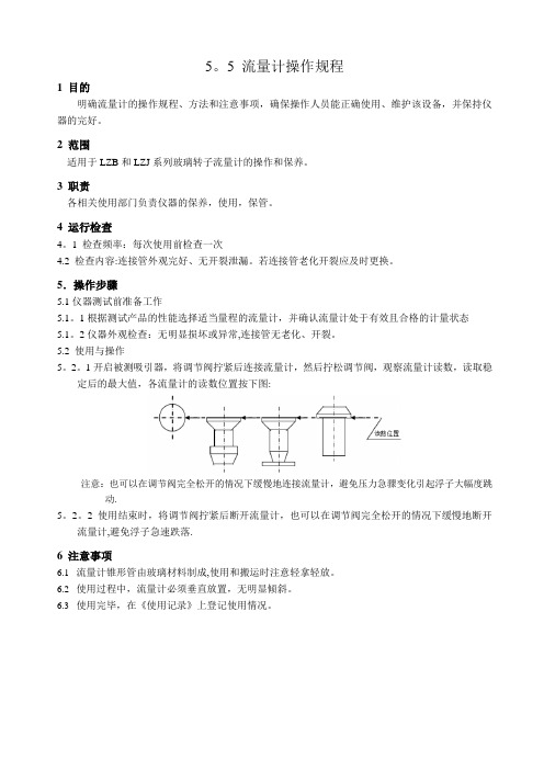
1开启被测吸引器,将调节阀拧紧后连接流量计,然后拧松调节阀,观察流量计读数,读取稳定后的最大值,各流量计的读数位置按下图:
注意:也可以在调节阀完全松开的情况下缓慢地连接流量计,避免压力急骤变化引起浮子大幅度跳动.
5。
2。
2 使用结束时,将调节阀拧紧后断开流量计,也可以在调节阀完全松开的情况下缓慢地断开流量计,避免浮子急速跌落.
6 注意事项
6.1流量计锥形管由玻璃材料制成,使用和搬运时注意轻拿轻放。
6.2使用过程中,流量计必须垂直放置,无明显倾斜。
6.3使用完毕,在《使用记录》上登记使用情况。
COMPANY 液体流量计安装、操作和维护手册说明书
C O M PA N YInstallation, Operating & Maintenance ManualLiquid Flow Meters ©2016 AW-Lake Company. All rights reserved. Doc ID:FLOWLIQUIDMETERMAN082516Materials of Construction (Wetted Components)23Mechanical - Size CodeIntroductionThis manual is a service guide produced by the manufacturer and provides specific procedures and/or illustrations for disassembly, assembly, inspection, cleaning, and filtration. When followed properly, these procedures will keep your flow meter in top operating condition.It is important for operators and maintenance personnel to be safety conscious when operating or repairing equipment. Developing a thorough knowledge of the precautionary areas and following safe operating procedures can prevent equipment damage and/or personal injury. Before making any repair, read all of the repair procedures to learn the correct method and all precautions.Table of ContentsSpecifications and General Information.........................................................2-3 Basic Application Information.........................................................4 Warning and Precautionary Areas...................................................4Installation ........................................................................................................5 Basic Installation Instructions..........................................................5 Fluid Flow in Reverse Direction......................................................6 Bi-Directional Flow Measurement....................................................7Operation...........................................................................................................7 Operating Principles.....................................................................7 Reading the Meter. (8)Specific Gravity or Density Effect (8)Viscosity Effect (9)Troubleshooting & Maintenance (10)Disassembly (11)Cleaning and Inspection (12)Contamination and Filtration (13)Recommended Filtration (13)Contamination Sources (13)Basic Application InformationThe flow meter can be installed directly in the fluid line without flow straighteners or special piping. The meter is used to measure the flow rate of most liquidswhich do not contain particles greater than 74 micron.1. The flow indicator is sealed inside the Polycarbonate or Pyrex window tubeto permit use in areas where the meter may be sprayed or washed with soapand water.2. Mount the meter in the most convenient location to allow easy access forreading and maintenance.3. The meter should NOT be mounted near hot pipes or equipment which cancause deformation of the window tube and scale (Polycarbonate tube only).4. The meter should be mounted at least one foot (.3 meter) from large electricmotors, or the internal magnet may weaken or become demagnetized.Warning and Precautionary Areas1. The standard meters are designed to operate in systems that flow in onlyone direction: the direction of the arrow on the flow scale. Attemptingoperation in the reverse direction may cause damage to the meter or othersystem components. (See page 6-7 for reverse and bi-directional flowoptions)2. The window tubes of standard meters are made of Polycarbonate. Be sure touse cleaning agents only compatible with Polycarbonate.3. To retain accuracy and repeatability many internal moving parts are precisionmachined and require filtration of at least 74 micron or a 200 mesh screen.4. All meters are tested and calibrated at our test facility using a light hydraulicoil (DTE-25®) or water. The units are well drained, but some oil residue maystill remain within the meters. Please check the compatibility with your fluid.The meter may have to be cleaned before use. (See “Cleaning & Inspection”section)45. When installing aluminum or brass meters onto steel pipe caution should be taken not to over tighten the pipe connections. The thread in the meter end fittings may strip if over tightened.6. It is not recommended to install meters to unsupported piping.7. Operating Temperature: In standard meters, several components have a maximum temperature rating of 240°F (116°C). High temp version: 400°F (204°C) and Ultra high temp version: 600°F (315°C).8. Operating Pressure: Meters should not be used above the maximum rated operating pressure.9. Pressure and flow surges may disengage the outer magnet follower fromthe transfer magnet. If this occurs, a shock suppressor should be used to eliminate malfunction.10. Thread seal tape: Caution should be used when using thread seal tape on pipe thread joints. Leave the first thread of pipe thread exposed from end of pipe when applying tape.11. These meters, as well as many other meters, use an internal transfer magnet in the design. Because of this magnet, be aware of the following:a) Do not install near highly magnetic devicesb) If metal particles are moving through the system, a magneticfilter may be required.WARNING: Never subject an empty flow meter to an immediate high fluid flow. Always purge air from meters by gradually increasing system fluid flow.A sudden slug of high velocity liquid into an empty flow meter can cause permanent damage to the internals.InstallationBasic Installation InstructionsThe meters are mounted in-line and are direct reading. The meters can be mounted in a vertical or horizontal position as long as the fluid is flowing in the direction of the arrow on the flow scale. No straight pipe is required before or after the meter.When installing a meter, apply “Thread seal Tape” or “Liquid Thread Sealant”on pipe threads. If tape is used, be sure to leave the first pipe thread on end of pipe exposed. Position filter in front of meter and in a location that allows easy access for routine maintenance. Refer to “Warnings and Precautionary Areas” for additional information.5INSTALLATION DOS AND DON’TTo obtain satisfactory operation from a flow meter, the following points should be considered:DO:• Install a pressure gauge near the inlet of the meter• Place throttling valves at the outlet of the meter• Use pipe sealer on the connections• Install a union on one side of the meter for easy removal for maintenance andcalibration• Install solenoid valves at meter outlet (as far downstream as possible)• Mount either vertically or horizontallyDO NOT:• Use in systems where reverse flow is possible unless using RF option• Place meter in non-aligned piping• Over-flow the meter by more than 150% of maximum reading• Operate at pressures and temperatures greater than specified• Install restrictions between pressure gauges and the meter inlet• Install solenoid valves at the meter inletFluid Flow in Reverse DirectionThe standard meter should not see flow in the reverse direction (oppositedirection to the arrow on the flow rate scale). Prolonged flow in the reversedirection will cause damage to the standard meter’s internal mechanism that could result in inaccurate readings or premature failure of the meter. If the standardmeter will be installed in a system where reverse flow is possible, the factoryrecommends that a check valve be installed in parallel with the meter in orderto facilitate reverse flow around the meter. Check valves are readily availablethrough fluid component distributors.Alternatively, flow meters designed to allow reverse flow may be specified.These meters do not measure in reverse flow, for that Bi-Directional meters are available. These meters are designated by a “-RF” suffix attached to the end of the standard 8-digit model code.Reverse flow meters will allow flows in the reverse direction of up to themaximum flow rate on the flow rate scale without any damage to the meter’sinternals.6Bi-Directional Flow MeasurementIn certain situations it may be necessary to measure flow rates in both directions. For a small additional fee, an option for bi-directional flow measurement may be specified. Meters that include this option are designated by a “-BI” suffix attached to the end of the standard 8-digit model code.*Not all flow ranges are available in Bi-Directional meters. Contact factory for more information on reverse and bi-directional flow.OperationOperating PrinciplesWe have developed a line of unique flow meters which combine the simplicity ofa sharp-edged orifice disk and a variable area flow meter. See Illustration 1 “Flow Meter Cross Section”.The meters are tubular, with all internal wetted parts sealed within the body casing. Running through the center of the body casing is a tapered center shaft which is centered in the bore by pilot disks at each end. Encircling the shaft isa sharp-edged, floating orifice disk, transfer magnet and return spring. The disk and transfer magnet are held in the “no flow” position by the biased return spring. As the flow moves through the meter it creates a pressure differential across the floating orifice disk, forcing the disk and transfer magnet against the return spring. As flow increases, the pressure differential across the disk increases, forcingthe disk and transfer magnet to move along the tapered center shaft. As flow decreases, the biased return spring forces the disk and transfer magnet down the tapered center shaft, returning to the “no flow” position.In metal casing meters the movement of the floating orifice disk and transfer magnet cannot be seen because they are sealed inside the body casing. Therefore, a magnet follower is positioned around the outside of the body casing and is magnetically coupled to the internal transfer magnet. As the flow rate increases, the internal magnet moves along the tapered center shaft (inside the body casing) and the magnet follower moves along the outside of the body casing (under the scale).7Reading the MeterNotice the black reference line which runs 360° around the white magneticfollower. This reference line moves under the scale in direct relation to themovement of the internal orifice disk. When fluid is flowing, the flow rate through the meter is read by lining up the black reference line with the closest rate line on the external flow scale.Specific Gravity or Density EffectStandard meters are calibrated for either water with a specific gravity of 1.0 oroil with a specific gravity of .873. The meter is affected by fluid density as aremost other similar type meters. Our meters have less of this effect because ofthe sharpness of the floating orifice disks being used. The indicated flow reading will read high for heavier fluids and low for lighter fluids. A corrective factor can be applied to the standard scale or a special scale can be added at a slightadditional costs. When measuring fluids with other specific gravities, the basicequations below can be used to develop corrected readings.For water meters use: √ 1.0/specific gravity x scale readingFor oil meters use: √.873/specific gravity x scale reading8Viscosity EffectThe meters incorporate a unique floating, sharp-edged orifice disk. The floating, sharp-edged orifice disk offers greater operating stability and accuracy overa wide range of viscosities. Standard viscosities up to 110 cSt. For viscosities between 110 to 430 cSt contact factory.Special ScalesSpecial calibrations can be performed by the factory to correct for the following system characteristics:• System temperature• Media specific gravity• Various measuring units (i.e. LPM, LPS, m3/hr, etc.)• Viscosity• Any combination of the aboveConsult factory or your distributor for details and prices.9Troubleshooting & Maintenance1011DisassemblyIMPORTANT: It is not necessary to remove window tube or window seals to clean the meter. Note also how the meter disassembles for ease of reassembly.WARNING: Shut down system before removing meter from flow line.1. Use a clean dry cloth to remove all foreign material from exterior of meter, especially around threaded ends.2. Remove meter from the flow line.3. With the arrow on the scale pointing upward, mount the meter in a vice. See Illustration 2. Use the flats of the inlet end porting when securing the meter in the vice.IMPORTANT: DO NOT wrench or tighten vice on window tube.4. Install a wrench across the flats of the outlet end porting and turn counterclockwise to loosen assembly. Do not remove end porting at this time.5. Remove meter from vice. Hold the meter so the end port that is loose, is on top. Remove loose end porting.Illustration 2Illustration 36. Tilt the open end of meter over a clean cloth to expose inner cartridge.See Illustration 3. Remove inner cartridge assembly from body casing.Note: Because the transfer magnet is magnetically coupled to the magneticfollower, you will notice a slight resistance when removing cartridge. Ifcartridge does not slide out, insert a wooden dowel in opposite end of meterand push or lightly tap on dowel until cartridge comes loose.IMPORTANT: If inner cartridge does not slide out freely, it may be sign ofcontamination. The transfer magnet is a powerful magnet. Keep it away frommetal chips and fillings. They may be hard to remove when reassembling and will cause premature failure.7. Examine inner cartridge or level of contamination.8. If inner cartridge has a low level of contamination and is functioning properly,no further disassembly is required. Proceed to “Cleaning and Inspection. Ifthe inner cartridge is damaged or contaminated beyond repair, the completemeter can be sent to the manufacturer for evaluation. The manufacturer willrepair or replace parts as needed.Cleaning & Inspection1. Inspect inner cartridge and body casing for contamination. If the innercartridge did not slide out freely, it may be a sign of contamination. Locateand eliminate the source of contamination before reconnecting meter to thesystem or the same problem will reoccur. It may be necessary to install finerfiltration or a magnetic filter in the system.2. Soak inner cartridge assembly in a suitable cleaning solvent. Naptha orStoddard is recommended.3. Remove parts from solvent. Use an air hose and/or scrub with a light brushto remove any remaining contaminants. Remove any magnetized particlesfrom transfer magnet.4. Inspect inner cartridge for scored or worn parts.5. Remove any contaminants from inside body casing.6. Clean the window tube with soap and water, or a compatible cleaningsolvent.IMPORTANT: Some solvents may cause damage to the polycarbonate tube,check compatibility of solvent being used.7. Clean and inspect seal assemblies (O-rings and seals) for nicks or cuts.Replace as needed.12Properly filtered meters will provide years of trouble-free service. If the meter is not properly filtered, it may be damaged and malfunction. Meter damage causedby excessive contamination is not covered under warranty. Contamination and FiltrationRecommended FiltrationThe manufacturer recommends system filtration of at least 74 micron filter ora 200 mesh screen. It has been found that if inadequate filtration has caused meter failure, it will normally fail in the open position. Some systems may requirea magnetic filter.IMPORTANT: Meter damage caused by excessive contamination is not covered under warranty.Contamination SourcesFresh FluidWhen fresh fluid is stored in holding tanks, it may be contaminated with scale or metal flakes from inside the tank. To prevent this type of contamination, be sureto filter fresh fluid before adding to the system.New Machinery ContaminationWhen building new machines, a certain amount of built-in contamination is unavoidable. Typical built-in contamination consists of dust, dirt, chips, fiber, sand, flushing solutions, moisture, weld splatters and pipe sealants. Flushing the system before operation can reduce contamination, but cannot eliminate it totally. Unless the system is flushed at a high velocity, some contamination will not be dislodged until the system is in operation. System contamination can cause fluid component malfunction.Environmental ContaminationWhen performing routine maintenance, the system’s fluid is commonly exposedto environmental contamination. Exercise caution during routine maintenance to prevent this type of contamination. Be sure to change breather filter and systems air filter regularly.Self-Generation ContaminationSelf-generated contamination is a product of wear, cavitation, fluid breakdown and corrosion. Systems that are carefully flushed, maintained, and have fresh fluid added, mainly have self-generated contamination. In this case, proper filtration can prevent fluid component malfunction.131415414.574.4300 | 2440 W. Corporate Preserve Dr. #600, Oak Creek, WI, 53154C O M PA N Y©2016 AW-Lake Company. All rights reserved. Doc ID:FLOWLIQUIDMETERMAN082516。
流量计说明书.pdf_1718715200.0919275

TABLE OF CONTENTS Introduction (4)Specifications (6)Installation (7)Operational Start-Up (9)Troubleshooting (11)Flow Monitor Information (12)Repair Kit Information (13)Statement of Warranty (15)INTRODUCTIONFluid entering the meter passes through the inlet flow straightener which reduces its turbulent flow pattern and improves the fluid’s velocity profile. Fluid then passes through the turbine blades causing it to rotate at a speed proportional to the fluid velocity. As each blade passes through the magnetic field, created at the base of the pickoff transducer, AC voltage (pulse) is generated in the pick-up coil (see Figure 1). These impulses produce an output frequency proportional to the volumetric flow through the meter. The output frequency is used to represent flow rate and/or totalization of fluid passing through the turbine flow meter.FIGURE 1Schematic illustration of electric signalgenerated by rotor movementTURBINE METERThe FTB-1400 Series Turbine Flow Meter is designed to withstand the rigorous demands of the most remote flow measurement applications. The FTB-1400 Series Flow Meter maintains measurement accuracy and mechanical integrity in the corrosive and abrasive fluids commonly found in oil field waterflood project pipelines, in-situ mining operations, offshore facilities and plant locations. Simple to install and service, it can operate in any orientation (horizontal to vertical) as long as the“flow direction” arrow is aligned in the same direction as the actual line flow. For optimum performance, the flow meter should be installed with a minimum of 10 diameters upstream pipe length and 5 diameters downstream pipe length.FIGURE 2Typical cross-section of FTB-1411 throughFTB-1441 turbine flow meterSPECIFICATIONSMATERIALS of CONSTRUCTION: Body : 316 Stainless SteelRotor : CD4MCU Stainless SteelRotor Support and Bearings : 316 Stainless SteelRotor Shaft : Tungsten CarbideOPERATING LIMITATIONS:Temperature: -150 °F to +350 °F (-101 °C to +177 °C) The metershould not be subjected to temperatures above +350° F(177° C), or below -150° F (-101° C) or the freezingpoint of the metered liquid. High temperatures willdamage the magnetic pick-up, while lower temperatureswill limit the rotation of the rotor.Pressure : Maximum pressure ratings as follows:5,000 psi ─ all NPT meters up to 2"2,000 psi ─ 3" male NPT1,500 psi ─ 4" male NPT1,000 psi ─ 6" male NPT800 psi ─ all grooved end metersNote: Consult factory for pressure ratings for flanged meters. Accuracy:± 1.0% of reading Repeatability: ± 0.1%Calibration: Water (NIST Traceable Calibration) Corrosion: All FTB-1400 series turbine meters are constructed ofstainless steel and tungsten carbide. The operator mustensure that the operating fluid is compatible with thesematerials. Incompatible fluids can cause deterioration ofinternal components and cause a reduction in meteraccuracy.Pulsation andVibration: Severe pulsation and mechanical vibration will affectaccuracy and shorten the life of the meterFiltration: If small particles are present in the fluid, it is recommendedthat a strainer be installed upstream of the meter (see Table 1 WARNING: Pressure in excess of allowable rating may cause the housing to burst and cause serious personal injury.FLOW MONITOR:For a complete flow monitor package, Omega offers the FTB-1400 Series Flow Monitors (see Appendix B on page 12 for flow monitor information). These digital signal processing displays utilize the low-level frequency input from the FTB-1400 Series Turbine Meters to calculate flow rate and total. When ordered with an Omega FTB-1400 Series Turbine Meter, the included factory calibration will provide dependable and accurate flow information.REPAIR KIT:The FTB-1400 Series Turbine Meter Repair Kit is designed for easy field service of a damaged flow meter, rather than replacing the entire flow meter (see Appendix B on page 12 for repair kit information).Repair parts are constructed of stainless steel alloy and tungsten carbide and are factory calibrated to ensure accuracy throughout the entire flow range. Each kit is complete and includes the calibrated K-factor which is used to recalibrate the flow monitor or other electronics to provide accurate output data.INSTALLATION INSTRUCTIONSPrior to installation, the flow meter should be checked internally for foreign material and to ensure the turbine rotor spins freely. Fluid lines should also be checked and cleared of all debris.The flow meter must be installed with the flow arrow, etched on the exterior of the meter body, pointing in the direction of fluid flow. Though the meter is designed to function in any position it is recommended, where possible, to install horizontally with the magnetic pick-up facing upward.The liquid being measured should be free of any large particles that may obstruct rotation of the rotor. If particles are present, a mesh strainer should be installed upstream before operation of the flow meter. (See Table 1 on page 8.)TABLE 1 Strainer Mesh Installation DetailsThe preferred plumbing setup is one containing a by-pass line (Figure 3 on page 10) that allows meter inspection and repair without interrupting flow. If a by-pass line is not utilized, it is important that all control valves be located downstream of the flow meter (Figure 4 on page 10).This is true with any restriction in the flow line that may cause the liquid to flash. If necessary, air eliminators should be installed to ensure that the meter is not incorrectly measuring entrained air or gas.PARTNUMBER STRAINER MESH CLEARANCE FILTER SIZE FTB-1411, FTB-142160 × 60 .0092 260 Micron FTB-1412, FTB-142260 × 60 .0092 260 Micron FTB-1413, FTB-142360 × 60 .0092 260 Micron FTB-142460 × 60 .0092 260 Micron FTB-1425 60 × 60 .0092 260 MicronFTB-1431 20 × 20 .0340 .86mm FTB-1441 20 × 20 .0340 .86mmCAUTION: Damage can be caused by striking an empty meter with a high velocity flow stream.It is recommended that a minimum length, equal to ten (10) pipe diameters of straight pipe, be installed on the upstream side and five (5) diameters on the downstream side of the flow meter. Otherwise, meter accuracy may be affected. Piping should be the same size as the meter bore or threaded port size.Do not locate the flow meter or connection cable close to electric motors, transformers, sparking devices, high voltage lines, or place connecting cable in conduit with wires furnishing power for such devices. These devices can induce false signals in the flow meter coil or cable, causing the meter to read inaccurately.If problems arise with the flow meter and monitor, consult Appendix A (Troubleshooting Guide) on page 11. If further problems arise, consult the factory.If the internal components of the turbine flow meter are damaged beyond repair, turbine meter repair kits are available. Information pertaining to the turbine meter repair kits is referenced in Appendix B on page 12.OPERATIONAL START-UPThe following steps should be followed when installing and starting the meter.WARNING: Make sure that fluid flow has been shut off and pressure in the line released before attempting to install the meter in an existing system.1. After meter installation, close the isolation valves and open theby-pass valve. Flow liquid through the by-pass valve for sufficient time to eliminate any air or gas in the flow line.CAUTION: High velocity air or gas may damage the internal components of the meter.2. Open upstream isolating valve slowly to eliminate hydraulic shockwhile charging the meter with the liquid. Open the valve to full3. Open downstream isolating valve to permit meter to operate.4. Close the by-pass valve to a full closed position.5. Adjust the downstream valve to provide the required flow ratethrough the meter. Note: The downstream valve may be used as a control valve.FIGURE 3Meter installation utilizing a by-pass line(Shown with an FTB-1400 Series Flow Monitor)FIGURE 4Meter installation without utilizing a by-pass lineAPPENDIX ATROUBLESHOOTING GUIDE Trouble Possible Cause RemedyMeter indicates higher than actual flow rate -Cavitation-Debris on rotor support-Build up of foreign materialon meter bore-Gas in liquid-Increase back pressure-Clean meter-Clean meter-Install gas eliminatorahead of meterMeter indicates lower than actual flow rate -Debris on rotor-Worn bearing-Viscosity higher than calibrated-Clean meter and add filter-Clean meter and add filter-Recalibrate monitorErratic system indication, meter alone works well (remote monitor application only) Ground loop in shielding Ground shield one placeonly. Look for internalelectronic instrumentground. Reroute cablesaway from electrical noiseIndicator shows flow when shut off Mechanical vibration causesrotor to oscillate without turningIsolate meterNo flow indication. Full or partial open position Fluid shock, full flow into drymeter or impact caused bearingseparation or broken rotor shaftRebuild meter with repairkit and recalibrate monitor.Move to location wheremeter is full on start-up oradd downstream flowcontrol valveErratic indication at low flow, good indication at high flow Rotor has foreign materialwrapped around itClean meter and add filterNo flow indication Faulty pick-up Replace pick-upSystem works perfect, except indicates lower flow over entire range By-pass flow, leak Repair or replace by-passvalves, or faulty solenoidvalvesMeter indicating highflow, upstream pipingat meter smaller thanmeter boreFluid jet impingement on rotor Change pipingOpposite effects of above Viscosity lower than calibrated Change temperature,change fluid or recalibratemeter11APPENDIX BFTB-1400 SERIES FLOW MONITOR Simplified Version• Displays rate and/or total• Large 8 digit by 3/4” display• Front panel programming• NEMA 4X enclosure• Five selectable units of measure• Programs in seven simple stepsPart Number InformationFTB 1400 X DMounting StyleM = Meter MountR =Remote MountS =Swivel Mount Advanced Version• Displays rate and/or total• Large 8 digit by 3/4” display• Front panel programming• NEMA 4X enclosure• Thirteen selectable units of measure• Selection of time intervals for rate measurement• Ten point linearization• Provides additional programming optionsPart Number InformationFTB 1400 X D AMounting StyleM = Meter MountR =Remote MountS =Swivel Mount1213FTB-1400 REPAIR KITFigure 5Typical turbine meter component directoryFlow Meter SizeRepair Kit FitsMeter Part NumberRepair KitPart Number3/8" FTB-1411,FTB-1421 FTB-1400A-RK 1/2" FTB-1412, FTB-1422 FTB-1400B-RK 3/4" FTB-1413, FTB-1423 FTB-1400C-RK 7/8" FTB-1424 FTB-1400D-RK 1" FTB-1425 FTB-1400E-RK 1-1/2" FTB-1431 FTB-1400F-RK 2" LowFTB-1441 FTB-1400F-RK Standard Magnetic Pick-upAll Meter SizesFTB-1400-MPNOTES 141516。
电磁流量计安装使用说明书
1 安全指南
1 安全指南
1.1 用途
• 本测量设备仅用于测量密闭管道中导电介质的流量。测量去离子水时,介 质的最小电导率为 20 μS/cm。对于大部分液体,测量时需要的最小电导率 可为 5 μS/cm。 • 除本文指定用途外,其它任何用途均会对人员和整个测量系统的安全造成 威胁,禁止使用。 • 制造商对由于不恰当使用或用于非指定用途而引起的损坏不承担责任。
-4-
1000系列电磁流量计 1000系列电磁流量计 2.1工作原理
法拉第感应定律(指的是当导体通过磁场时会在导体内部产生感应电势)即 为电磁流量计测量的基础原理。这种测量原理可应用于具有导电性的流体,该 流体流入磁场垂直于流体方向的管道,在流体中感应生成的电势可利用对称布 置的两个电极进行测量。信号电压UE与磁感应强度B,电极间距D以及流体平均 速度v成正比。由于磁感应强度B与电极间距D为常量,所以信号电压UE与平均 流速v成正比。用于计算体积流速的等式表明信号电压UE与体积流量成线性正 比。
-6-
1000系列电磁流量计 2.4电磁流量计的主要技术参数 2.4.1 标准型和高精度型技术参数
型号
TK1100标准型系列
TK1200高精度系列
口径
DN3-DN2200
DN10-DN1200
精度
0.5%
0.2%,0.3%
安装方式
夹持,法兰
夹持,法兰
重复性 测量范围
0.1% 0-12m/s(流量单位可改变)
-7-
1000系列电磁流量计
2.4.2 卫生型和电池供电型技术参数
型号 口径 精度
TK1300卫生型系列 DN3-DN150 0.2%,0.5%
TK1500电池供电系列 DN10-DN1200 0.5%