PVH变量柱塞泵使用说明书
PVS系列可变容积柱塞泵说明书
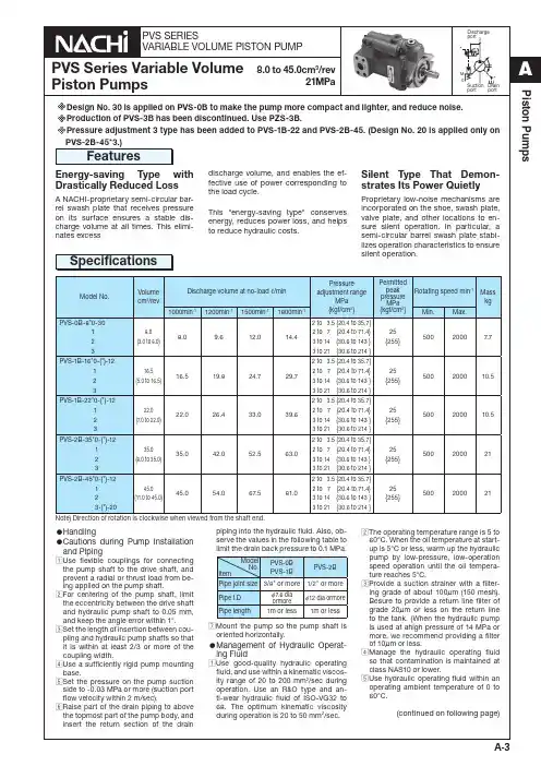
PVS-2B-45*3.)Features SpecificationsModel No.Volumecm3/revDischarge volume at no-load ℓ/min 1000minEnergy-saving Type with Drastically Reduced LossA NACHI-proprietary semi-circular bar-rel swash plate that receives pressureExplanation of model No.PVS – 1 B – 16 N 2 – (*) – 12Design No. 30: PVS-0*12: PVS-1*, PVS-2*20: PVS-2*-45N3 onlyVariable Control MechanismsStandard typeSymbol External View CharacteristicsPressurePVS-0B-8N*-30General PerformanceManual mode: standard typeTypical characteristics at hydraulic operating fluid kinematic viscosity of 32 mm Pressure Compensation TypeInstallation Dimension DrawingCross-sectional DrawingPerformance Curves3334271722251620103835281512112426211829473Pressure compensatorMINDrain portRc(Former PT)3/8Lock nutLock nut164.5(MAX)( ow rateadjustmentlength)1861449.5214( MAX)510Pressureadjusting screw Discharge volume Q 1800m in –115141314e v o l u m e e v o l u m e(side port type)PVS-1B-1622N*-(Z)-12Installation Dimension DrawingsCross-sectional Drawing761631221721351539303841Typical characteristics at hydraulic fluid kinematic viscosity of 32 mm Performance CurvesPerformance CurvesPVS-1B-16N*-(Z)-12PVS-1B-22N*-(Z)-12401800min –1Discharge u m e u m e 302830o l u m e o l u m e General PerformanceGeneral PerformanceTypical characteristics at hydraulic operating fluid kinematic viscosity of 32 mm(side port type)PVS-2B-3545N*-(Z)-12(20)PVS-2B-3545N*-(Z)-12Installation Dimension DrawingsCross-sectional Drawings1222153921297617361642323031193541317.5 (MAX)General Performance General Performance Typical characteristics at hydraulic operating fluid kinematic viscosity of 32 mm Typical characteristics at hydraulic operating fluid kinematic viscosity of 32 mmPerformance Curves Performance Curves PVS-2B-35N*-(Z)-12PVS-2B-45N*-(Z)-12(20)65e80e ePressure CompensatorResponse Performance911314532101112Test CircuitPiping volume 400 cm 3The ZR-T02-*-5895* is the recommended remote control valve.Provide piping to the remote control valve at a pipe volume of 150 cm Design No. 30: PVS-0*12: PVS-1*, PVS-2*(remote control mode)Pressure Compensation TypeExplanation of model No.: PVS – 0 B – 8 P * – 30PVS-0B-8P*-30Installation Dimension Drawings164.5(MAX )214(MAX )( ow rate adjust-649.593.518Design No.12: PVS-1*, PVS-2* 20: PVS-2*-45N3Q*2-pressure, 2-flow Rate Control TypeExplanation of model No.: PVS – 1 B – 16 N 3 Q 1 – 12Installation Dimension DrawingsPVS-1B-1622N*Q*-1277.549.5301.5(MAX)23Drain port P2 pressurePVS-1B-1622R*AS*-12Solenoid power supply Installation Dimension DrawingsSolenoid Cutoff Control TypeExplanation of model No.: PVS – 1 B – 16 R 2 S 1 – 12200.32-pressure Control Type Explanation of model No.: PVS – 1 B – 16 W 2 S 1 – 12Installation Dimension Drawings PVS-1B-1622W*A S*-122-pressure, 2-flow rate Control Type w/ Solenoid CutoffSolenoid power supply 1: AC100V2: AC200V P-Q CharacteristicsExplanation of model No.: PVS – 1 B – 16 RQ 2 S 1 – 12PVS-1B-1622RQ*A S*-12Installation Dimension Drawings301.5(MAX)yqq12-cutoff Control Type Explanation of model No.: PVS – 1 B – 16 C 2 S 1 – 12Installation Dimension Drawings PVS-1B-1622C*A S*-12Foot Mounting KitCoupling kitPiping Flange KitApplicable Pump Model No.Accessories Bolt Q'ty Washer Q'ty A PVS-0B PVS-1B TB-10×302WP-102127152.5Kit for PVS-0B: PSCF-100000For PVS-1B, 2BUni-pump Specifications(CE mark standard compliant) Explanation of model No.UPV – 1 A – 16 N 1 – 1.5 * – 4 * – * – 30(50)(3.7kW only)Hanging bolt Hanging bolt Flow rate adjusting screw M8UPV-0A-8**-**-4-50Installation Dimension Drawings(side port type)。
PARKER派克PV型柱塞泵技术使用操作资料
PARKER派克PV型柱塞泵技术使用操作资料PARKER派克PV型柱塞泵技术使用操作资料PARKER派克PV型柱塞泵按泵的工作压力分为低压泵(压力小于2.5Mpa)、中压泵(压力为2.5Mpa~8Mpa)、中髙压泵(压力为8 Mpa~16Mpa)、高压泵(压力为16Mpa~32Mpa)和超髙压泵(压力大于32Mpa)。
各种派克柱塞泵都可以制造成定量泵,如齿轮泵(外啮合式、内啮合式)、叶片泵(单作用式、双作用式)、柱塞泵〔轴向式、径向式)和螺扞泵(双螺杆式、三螺杆式);有的派克柱塞泵能制造成变量泵,如单作用叶片泵、轴向柱塞泵和径向柱塞泵。
PARKER派克柱塞泵都是依靠密封容积变更的原理来进行工作的,故一般称为容积式派克柱塞泵。
是一单柱塞派克柱塞泵的工作原理图。
派克塞泵重要由偏心轮、柱塞、缸体、弹簧、排油单向阀和吸油单向阀等构成。
派克柱塞泵重要特点及功能1、节电效果达3070%。
2、电机软启动,削减对机械的撞击。
3、无高压节流能量损失。
4、具有欠压、过压、过载、短路、缺相等自动保护。
5、替换原来系统。
降低采购产品本钱(新设备购买)。
6、削减机械的维护和修理本钱。
7、操作简单、可实现远程掌控。
Parker派克PV系列轴向柱塞泵有带标准压力调整器和带功率调整器两种选择。
z大排量从16至270ml/rev,额定工作压力为350bar,z低转速为每分钟300转,PARKER柱塞泵依据倾斜元件的不同,有斜盘式和斜轴式两种。
斜盘式是斜盘相对回转的缸体有一倾斜角度,而引起柱塞在泵缸中往复运动。
传动轴轴线和缸体轴线是*的。
这种结构较简单,转速较高,但工作条件要求高,PARKER柱塞端部与斜盘的接触部往往是软弱环节。
斜轴式的斜盘轴线与传动轴轴线是*的。
它是由于柱塞缸体相对传动轴倾斜一角度而使柱塞作往复运动。
流量调整依靠摇摆柱塞缸体的角度来实现,故有的又称摆缸式。
它与斜盘式相比,工作牢靠,流量大,但结构多而杂。
大后方对PARKER柱塞泵产品特别执着,在液压行业PARKER产品在大后方液压算是重点的产品,以致一直得到同行业的大力支持。
柱塞泵说明书(2)
用户须知
一、在使用前请仔细阅读《使用说明书》。
二、请严格按照操作规程要求使用。
三、如再技术更新,概不通知用户。
四、在保修期内,凡未经拆动确属产品制造质量造成故障或
损坏,均由我公司负责免费修理或更换损坏的配件。
五、由于用户使用不当等人为造成的零配件损坏,我公司可
协助用户修复。
六、用户与我公司联系解决质量问题或调试时,请写明柱塞
泵型号,说明故障现象及供浆工艺性能要求。
七、用户在使用过程中有任何疑问,请与我公司技术部联系。
永昌机械有限公司
目录
一、特点与用途---------------------------1
二、主要技术参数-------------------------2
三、外形与配件---------------------------3
四、安装使用与维修-----------------------4
五、常见故障及排除方法-------------------8
六、安装基础图--------------------------10
七、液压系统图---------------------------11。
柱塞泵作业指导说明书
柱塞泵作业指导书工作原理:柱塞泵是往复泵一个,属于体积泵,其柱塞靠泵轴偏心转动驱动,往复运动,其吸入和排出阀全部是单向阀。
当柱塞外拉时,工作室内压力降低,出口阀关闭,低于进口压力时,进口阀打开,液体进入;柱塞内推时,工作室压力升高,进口阀关闭,高于出口压力时,出口阀打开,液体排出。
当传动轴带动缸体旋转时,斜盘将柱塞从缸体中拉出或推回,完成吸排油过程。
柱塞和缸孔组成工作容腔中油液经过配油盘分别和泵吸、排油腔相通。
变量机构用来改变斜盘倾角,经过调整斜盘倾角可改变泵排量。
作业步骤:1 开机前检验:1.1 检验全部管路、配件、螺栓和电路接线是否准备就绪。
1.2 检验全部管路接头部位密封情况是否达成要求。
1.3 全开储罐上回气截止阀、液相截止阀,检验泵吸入压力是否大于0.02MPa且小于1.0Pa。
2 开启:2.1 开启使用泵泵前阀门,缓慢地对泵进行冷却。
2.2 当预冷完成(冷却时间约为10分钟),根据CNG加气步骤,开启管路上阀门,开启泵。
2.3 检验泵开启是否正常。
正常开启工作,将有以下现象:1)有一泵排出管路开始结霜。
2)可听到轻微震动声,证实泵进、出阀正在工作。
3)排出管路上压力表将显示逐步增加压力。
2.4 本泵运转约5000小时后,为了确保十字头、滑套和连杆有更长使用寿命,可更换电机旋转方向。
2.5 假如汽化器最终一排翘片发生结霜现象或汽化器去储气瓶管路发生结霜现象或汽化器出口温度低压-5°C,表明系统流量已超出汽化器气化能力,应立即停泵,切换另一套设备使用。
1.2.5 假如泵发出异常声音,显示在压力管路中形成了过高压力,那么应立即停泵,并查找原因。
3 停泵:3.1 正常充装工作完成后,应点击操作台上停止钮,即停止变频器输出并关闭泵进液阀及汽化器进口阀,延时10秒打开泵出液放空阀放掉残液,同时常开回气阀。
3.2 假如系统出现故障,则应首先切断泵电机电源,停止泵工作,待故障排除后,再重新开启。
柱塞泵的使用方法
柱塞泵的使⽤⽅法⼀、开机前的准备⼯作1.检查柱塞泵的电机是否已经安装妥当,并确保电机旋转⽅向与泵的指示标志⼀致。
2.检查柱塞泵的电源连接是否牢固,并确保电源电压与电机额定电压⼀致。
3.检查柱塞泵的润滑系统,确保润滑油充⾜且清洁。
4.检查柱塞泵的进出⼝管道是否清洁,并确保管道连接牢固,⽆泄漏现象。
5.检查柱塞泵的泵体和电机部分,确保⽆异常声⾳和振动。
⼆、启动操作1.打开柱塞泵的进⼝阀⻔,确保进⼝管道充满介质。
2.按下柱塞泵的启动按钮,观察泵的旋转⽅向是否正确,电机是否正常⼯作。
3.调节进⼝阀⻔的开度,使泵的排出压⼒和流量符合要求。
4.观察柱塞泵的运⾏情况,如发现异常声⾳或振动,应⽴即停机检查。
三、运⾏维护1.定时检查柱塞泵的运⾏参数,如压⼒、流量、温度等,确保在正常范围内。
2.定时检查柱塞泵的润滑系统,确保润滑油充⾜且清洁。
如发现润滑油变质或不⾜,应及时更换或补充。
3.定时检查柱塞泵的进出⼝管道,确保管道连接牢固,⽆泄漏现象。
如发现泄漏现象,应及时处理。
4.定时检查柱塞泵的泵体和电机部分,确保⽆异常声⾳和振动。
如发现异常现象,应及时处理。
5.在使⽤过程中应避免超载运⾏,防⽌损坏电机和泵体。
6.在使⽤过程中应保持环境清洁,防⽌杂物进⼊泵内,影响泵的正常运⾏。
7.在使⽤过程中应保持电源电压稳定,防⽌电压波动对泵的运⾏造成影响。
8.在使⽤过程中应定期对泵进⾏维护保养,如清洗过滤器、更换润滑油等,以保证泵的正常运⾏和使⽤寿命。
9.在使⽤过程中应严格按照操作规程进⾏操作,避免违规操作对泵造成损坏。
10.在使⽤过程中应定期对泵进⾏检测和试验,确保其性能稳定可靠。
11.在使⽤过程中应注意观察泵的运⾏情况,如发现异常应及时停机检查并处理。
12.在使⽤过程中应保持安全意识,避免因操作不当导致的安全事故。
13.在使⽤过程中应做好记录和统计⼯作,以便于对泵的运⾏状况和维护保养情况进⾏跟踪和分析。
14.在使⽤过程中应加强与⽣产⼚家的沟通和联系,以便及时获取技术⽀持和帮助。
电动柱塞泵使用方法说明书
电动柱塞泵使用方法说明书一、泵概述电动柱塞泵是一种应用于工业领域的流体输送设备,其主要功能是将液体或气体从低压输送到高压,广泛应用于石油、化工、冶金等行业。
本说明书将详细介绍电动柱塞泵的使用方法。
二、安全须知在操作电动柱塞泵之前,请务必仔细阅读以下安全须知,并严格遵守:1. 在操作和维护设备时,必须佩戴符合要求的个人防护用品,包括安全帽、防护眼镜、耳塞、防护手套等。
2. 在操作泵时,禁止戴任何饰品,长发必须束起来,以防发生意外。
3. 在维护和清洁电动柱塞泵之前,务必将电源切断,并等待设备完全停止运转后进行操作。
4. 使用泵时,必须确保设备处于良好的工作状态,若发现任何异常情况,应立即停止操作,并进行维修。
5. 在进行维护或更换零部件时,应使用原厂配件,并根据说明书提供的操作步骤进行操作。
三、使用步骤1. 安装a. 将电动柱塞泵放置在平稳的工作台上,并通过螺丝固定。
b. 连接进出口管道,确保连接牢固且没有漏水。
c. 将电源线连接至泵的电源接口,并根据电源要求接通电源。
2. 开机准备a. 检查电动柱塞泵的所有开关、阀门是否处于关闭状态。
b. 打开进气阀,确保进气通畅,并检查泵的压力表是否工作正常。
c. 检查油液或液体储存容器是否有足够的填充量。
3. 启动电动柱塞泵a. 将电源开关切换至“ON”状态。
b. 打开电动柱塞泵的主控阀门,并逐渐调节至所需的工作压力。
c. 观察电动柱塞泵的工作状态,确保正常运转。
4. 关机a. 当工作完成或需要维修时,将电源开关切换至“OFF”状态。
b. 关闭主控阀门,切断电源,并等待电动柱塞泵完全停止工作。
c. 清洁泵体及周边区域,并妥善存放设备。
四、维护保养为保障电动柱塞泵的正常运行和延长使用寿命,请按照以下步骤进行维护保养:1. 定期检查电动柱塞泵的油液或液体储存容器,并及时更换。
2. 清洁电动柱塞泵的滤网和进、出口通道,确保畅通无阻。
3. 检查电动柱塞泵的零部件是否损坏或磨损,如有异常情况应及时更换。
PVH型液压油泵说明书
PVH Piston PumpsIncluding ControlsVickers ®Piston Pump sOverhaul ManualSection 1 – IntroductionA. Purpose of ManualThis manual describes basic operating characteristics and provides overhaul information for the VickersPVH 57/74/98/131 series piston pumps. The information contained herein pertains to the latest design series as shown in the model code.B. Related PublicationsInstallation dimensions for the PVH series pumps and controls are not included in this manual. Individual parts numbers for the basic pumps are also not included. Refer to the related publication list below for publications that include this type of information.PVH57Service drawing M–2206–SPVH74Service drawing M–2207–SPVH98Service drawing M–2208–SPVH131Service drawing M–2209–SPVH Series Application GB–C–2010C. Model Code DescriptionVariations within each basic model series are covered in the model code as shown on the next page. Service inquires should always include the complete unit model code number as stamped on the name plate, and the assembly number as stamped on the mounting flange.Model CodeN = ISO 3014/2- Short straight E32N keyed 1 =SAE ”C ”Straight(J744-32-1)keyed 2 =SAE “C ”G Splined 14 tooth(J744-32-4)12/24 D.P .3 =SAE “CC ” Splined 17 tooth (J744-38-4)12/24 D.P .12 = SAE “D ” Splined 13 tooth (J744-44-4) 8/16 D.P .13 = SAE “C Straight (J744-38-1) keyed 16 = SAE “D “ Straight(J744-44-1) keyedBlank = Non-thru-drive (single pump)A = Thru-drive pump with SAE“A ” 2-bolt rear flange mounting (SAE J744-82-2)B = Thru- drive pump with SAE “B ” 2- and 4-bolt rear flangemountings ♦(SAE J744-101-2/4)C = Thru-drive pump with SAE “C ” 2- and 4-bolt rear flange mountings ♦(SAE J744-127-2/4)S = Adjustable maximum volume stop (non-thru-drive andnon-torque-control pumps only)PVH *** QI * – * (*) * – ** * – 10 – C(M) ** (**) (**) – *0 – ***** = Customer desired torque limitersetting specified in ten bar (145 psi) increments, e.g.: 8 = 80 bar (1160 psi); 18 = 180 bar (2610 psi).The torque setting range is from 30–80% of the specified compensator setting.C = 70-250 bar (1015-3625 psi) (standard)CM = 40-130 bar ((580-1885 psi) (optional QI version)IC = Industrial controlUV = Unloading valve control for accumulator circuitsShaft seal, prime mover endS = Single, one-way (standard)D = Double, two-way (optional)Recommended on second pump of tandem assembly (PVH**/ PVH**)Maximum geometric displacement46810 57 = 57.4 cm 3/r (3.5 in 3/r) 74 = 73.7 cm 3/r (4.5 in 3/r) 98 = 98.3 cm 3/r (6.0 in 3/r)131 = 131.1 cm 3/r (8.0 in 3/r)711Mounting flange, prime mover endC = SAE “C ” 4–bolt type (SAE J744-127-4 )M = ISO 3019/2–125B4HW (Option for PVH57QI and PVH/74QI only)R = Right hand, clockwise (Standard on QI models)L = Left hand, counterclockwise (Optional on QI models)ConfigurationMain portsF = SAE 4-bolt flange pads (standard )M = SAE 4-bolt pads with metricmounting bolt threads (PVH57 & PVH74 only)Shaft-end type, at prime mover end9Pump design numberPressure compensatoradjustment rangeMobile pumpsIndustrial pumpsShaft rotation, viewed atprime mover end 5234567891112132PVH *** - C – * (*) * – ** * – 10 – C ** (**) (**) – *0 – ***1410Additional control functions13Blank = No additional controlsV = Load sensing, 20 bar differential pressure setting T = Torque limiterVT = Load sensing and torque limiterTorque limiter factory setting1415Control design number31 = C, CM, or C**V controls.13 = C**T controls 14 = C**VT controls 10 = UV and IC controls♦Built from pump with SAE “A ” rear pad to which suitable flange adapter is bolted. For best availability and flexibility,order PVH SAE “A ” thru-drive pump and SAE “B ” or “C ” adapter kit separately.10 (Subject to change. Installation dimensions unaltered for design numbers 10 to 19 inclusive. )245678910131415151225 = Normal factory setting of 250 bar for “C ” models.7 = Normal factory setting of 70 bar for “CM ” models.Pressure compensator factorysetting in tens of bar16Special features suffix027= Composite 2-bolt/4-bolt mounting conforming to SAE “C ” (except PVH131)031= Thru-drive SAE “A ” pad cover041= No case-to-inlet relief (for use with supercharged circuits)057= Shaft-up operation (vertical mount)Torque restrictions apply to #2 shaft inPVH74 and 98 thru-drive, and PVH131single and thru-drive, pumps. Vickers is not responsible for misapplied usage of these shafts. Please contact a Vickers representative for review of your application.G 111Piston pump, variabledisplacement11312163Industrial version16Section 2 – DescriptionA. Basic PumpFigure 1 shows the basic construction of the PVH series piston pump. Major parts include the drive shaft, housing,yoke, rotating group, valve plate, control piston, bias piston,valve block and compensator control. The PVH seriesreplaces the pintle bearing assembly with saddle bearings,which reduces weight and eliminates the roller bearings that added to maintenance time and overhaul costs.B. Pump ControlsTwo common pump control types are available. One type is the standard “C ” compensator control that limits pump outlet pressure to a desired level. The other type is the “CV ”pressure limiter/load sensing control. Now available is the “IC ” (Industrial Control) which can be used as a load sensing compensator, remote compensator control andelectrohydraulic control. These limit pump outlet pressure and also regulate pump displacement to match load requirements.Section 3 – Principles of OperationA. Pump OperationRotation of the pump drive shaft causes the cylinder block,shoe plate and pistons to rotate (See Figure 2). The piston shoes are held against the yoke face by the shoe plate. The angle of the yoke face creates a reciprocating motion to each piston within the cylinder block. Inlet and outlet ports connect to a kidney slotted wafer plate. As the pistons move out of the cylinder block, a vacuum is created and fluid is forced into the void by atmospheric pressure. The fluid moves with the cylinder block past the intake kidney slot.The motion of the piston reverses and fluid is pushed out of the cylinder block into the outlet port.WarningBefore breaking a circuit connection, make certain that power is off and system pressure has been released. Lower all vertical cylinders, dischargeaccumulators, and block any load whose movement could generate pressure. Plug all removed units and cap all lines to prevent the entry of dirt into the system.Figure 1. PVH Section ViewFigure 2. PVH Pump OperationYoke faceOutlet portInlet portDrive shaftInlet valve plate kidney slotInletValve blockBias pistonPistonB. Pump ControlsPressure Compensator Controls “C” & “CM”(Figure 3)The standard “C” and low pressure “CM” compensator controls are internally pilot operated, spring offset, 2-way valves. Their purpose is to limit system pressure to a desired level by varying pump displacement. These controls only provide the flow required to satisfy the load demand, while maintaining a constant preset pressure.During operation, load or system pressure is continually fed to the bias piston. The function of the bias piston is to maintain the yoke at a full pump displacement position. Load or system pressure is also fed to the compensator spool chamber within the control. Pressure within the compensator spool chamber acts upon the spring force of the compensator spring.When load or system pressure is below the pressure setting of the compensator spring, the compensator spool remains offset and the pump continues to operate at full displacement. When load or system pressure approaches the compensator pressure setting, the compensator spool will start to move and overcome the compensator spring force. Fluid will then meter into the control piston area. Since the control piston area is greater than that of the bias piston,the control piston pushes the yoke towards minimum pump displacement. The compensator control continues to meter fluid to the control piston, adjusting the pump displacement, and pumping only enough fluid to satisfy the load demand while holding the system at a constant pressure.When load or system pressure exceeds the compensator setting, the compensator spool shifts towards the spring chamber area. A maximum amount of fluid is then metered to the control piston area, causing the yoke to shift to minimum pump displacement.When system pressure decreases below the compensator pressure setting, the compensator spool returns to its original position and the yoke returns to maintain maximum pump displacement.The compensator is available in two pressure ranges. The “C” spring has an adjustment range of 70–250 bar(1015–3625 psi). The “CM” spring has an adjustment range of 40–130 bar (580–1885 psi).Figure 3. “C” & “CM” ControlsI DrPBody SpringTo tankPressure limiting spoolControl pistonYoke angleBias pistonPiston pumpLoad Sensing & Pressure Compensator Control C(M)*V (Figure 4)This pump will provide power matching of pump output to system load demand, maximizing efficiency and improving load metering characteristics of any directional control valve installed between the pump and the load.Load sensing ensures that the pump always provides only the amount of flow needed by the load. At the same time, the pump operating pressure adjusts to the actual load pressure plus a pressure differential required for the control action. Typically, the differential pressure is that between the pressure inlet and service port of a proportionally controlled directional valve, or a load sensing directional control valve. When the system is not demanding power, the load sense control can operate in an energy-saving stand-by mode. To achieve the low pressure, no flow, stand-by mode, the load sense signal line must be drained to the tank externally. The standard differential pressure setting for load sense is 20 bar (290 psi), but can be adjusted to between 17 and 30 bar (247 and 435 psi) on the pump.If the load pressure exceeds the system pressure setting,the pressure compensator de-strokes the pump. The load sensing line must be as short as possible and can also be used for remote control or unloading of the pump pressure.For remote control, it is recommended that you contact your Vickers representative for the correct configuration of the control.Figure 4: C(M)*V ControlInletLoad sense signal portOutletTo load1.7 bar (25 psi)Case drainPVH with UV Control for Accumulator Circuits (Figure 5)This pump control functions as a load- sensing pressure compensator that unloads the pump at a preset pressure and loads the pump after preset pressure drop.Figure 5: UV ControlOutlet1.7 bar (25 psi)•••••Pressure & Torque Limiter Control C**T (Figure 6)This pump senses pressure and flow and starts destroking at a predetermined input torque level. The rate of flowreduction is normally tailored to follow the maximum power capability curve of the prime mover. Input torque is limited while the pressure compensator limits the system pressure.When the input speed remains constant (i.e. industrialdrives), the torque limiter acts as an input power limiter. This allows a smaller electric motor to be used if maximum pressure and maximum flow are not required at the same time. At low load levels, the control permits high pump displacement and high load speeds. Under heavy loads,speed is reduced, preventing stalling of the prime mover. In the case of variable speed drives (I.C. engines), this function provides, in addition to pressure compensation or limiting, a torque limiting ability that can be adjusted to the torque/speed characteristics of the engine.The start of torque limiting (pump-destroking) is pressure dependent. The pressure is selectable (see model code) and is factory preset to between 30% and 80% of the maximum pressure control setting. The adjustment range for the “C ”compensator is 80 to 200 bar (1160 to 2900 psi) in 10 bar (145 psi) increments. There is no “CM ” spring option available with the torque limiting control.Figure 6: C**T ControlInletCase drainOutlet To load1.7 bar (25 psi)Torque Limiting Plus Load Sensing Control C**VT (Figure 7)This pump control option functions like a load sensingcontrol, but with additional torque limiting tailored to the size of the drive motor selected. The limiting function is the same as for a pressure compensator with torque limiting. The combination of the two controls provides the following benefits:1. The energy savings of a variable displacement load sensing control.2. The pump pressure follows the load pressure.3. The torque control allows smaller drive motors to be used.4. The pressure compensator de-strokes the pump as maximum pressure is reached.5. The pump pressure can also be remotely controlled using the load sense line. The C**VT control allows complete control of flow and pressure, either mechanically or electrically, if used with proportional valves.Figure 7: C**VT ControlCase drainInletLoad sense signal portTo loadOutlet1.7 bar (25 psi)Industrial Control (Figures 8 & 9)This pump control option is intended for use when multiple,remote, or electrically controlled compensating settings, with or without load sensing, are desired.Pressure compensation is obtained by removing an internal plug, keeping the load-sense signal port plugged, and internally applying pilot pressure to the spring chamber of the pilot-operated control spool. For pressure compensation with load sensing, the internal plug stays, the load-sense signal port is unplugged, and pilot pressure is externally applied.An external relief valve is used to set system pressure. The externally adjustable control-spool spring determines the differential pressure setting of the pump control. Pilot(spring chamber) pressure is separated from outlet pressure by an internal orifice. Outlet pressure shifts the spool when pressure drop across the orifice reaches the differential pressure setting, and the pump de-strokes.The relief valve can be mounted to an NFPA-D03/ISO 4401-03 pad on the pump control, or remotely located via tapping and blanking plates installed on the pad.The standard factory-set differential pressure setting of the pump control is 20 bar (290 psi) and is not specified in the pump model code. Any other ordered differential pressure,within the control ’s adjustable pressure range of 17–35 bar (247–508 psi), will be specified in the model code following the “IC ” control code; for example, “-IC30-” for a 30 bar setting.Application examples: Mounting Control TypeD EHSTElectrical control compensator D DG valve w/DGMC Double or triple compensator D C –175Remote control relief valve D CGE –02Electrical relief valveFigure 9: Industrial ControlCase drainInletOutlet To load1.7 bar (25 psi)Tank portPressure port ••••XLoad sense signal portInletLoad sense signal portOutlet To load1.7 bar (25 psi)X Tank portPressure port ••••C. Load Sensing/Pressure Limiting OperationAs one would expect from the title, this control is acombination of the features of both the pressure limiting and load sensing controls. Refer to Figure 10.The load sensing spool senses the pressure difference (pressure drop ∆P) between pump outlet and load pressure across a series flow control or system directional valve which is inherent in its operation. This differential pressure causes the load sensing spool to move against its spring to the closed –center position. If the differential pressure (pressure drop ∆P) increases (greater flow through the series valve), the load sensing spool moves to the right.Figure 10: Load Sensing Control SystemPressure SignalSpoolSensing Compensator AdjustmentPressure Limiting SpoolTo TankFlow Control or Dir. Valve Control Piston Piston PumpBias PistonThe load sensing portion of the control operates as a function of the pressure drop across the series valves(pressure drop ∆P), and is independent of system pressure.It establishes a constant flow characteristic from the pump based on the magnitude of the directional valve opening (operator controlled).If outlet pressure increases to the maximum pressure limit setting, the pressure limiting spool meters fluid to the control piston. The control piston moves the yoke to reduce flow. If outlet pressure continues to rise, the spool will continue to meter fluid to the control piston and the pump will stroke to zero flow at maximum pressure.Reduced horsepower standby featureWhen the system flow control valve or directional valve is closed completely, the circuit is placed in standby.NoteThis feature assumes the system flow controlvalve or directional valve provides decompressionof load sensing pressure in the standby, fullyclosed position. Pressure at point A (Figures 10 &11) must decay toward zero through the systemflow control or directional valve for standby tooccur. Decompression of the load sensingpressure allows the pump to stroke to zero flowand minimum pressure. The circuit functions in thefollowing manner.Assume the flow control or directional valve is closed and there is no bleed of point A (Figure 10) to tank. The fluid is trapped and the load sensing spool is held to the left by the spring. The system pressure rises until the pressure limiting spool takes over. The yoke then stokes to zero flow and holds pressure at the maximum limiter setting.If, in the closed condition, the flow control or system directional valve bleeds point A (Figures 10 & 11) to tank, the load sensing feedback pressure will decay. The load sensing spool will shift to the left. Fluid then meters through the pressure limiting spool and into the control piston. Outlet pressure decays through pump leakage following the decay of feedback pressure A (Figures 10 & 11) until minimum pressure drop is reached. The pump will operate in the standby mode (zero flow, minimum pressure) until the flow control or system directional valve demands flow from the pump. At this time, normal operation of the controlwill resume.D. Adjustment procedure:Load Sensing PressureLimiting ControlGeneralThis procedure contains information on the PVH pressure limiting and load sensing control. Test and adjustment procedures are provided for standard units.NotePressure gauges must be installed into the systembefore adjustment of the control can be performed.Complete field test adjustment procedures areincluded.Set upMake sure all machine controls are in the OFF or neutral position.Figure 11: Gauge Connection(A) Load pressureconnection(CT/CTS control) pressure gaugeConnect a 5000 psi pressure gauge at the outlet of the piston pump and on load sensing models, in the load sensing line.Check pump housing to verify that it is full of system fluid. Jog the engine to prime the pump, then exercise the controls to eliminate entrained air in the system.Pressure Limiter AdjustmentMove an appropriate cylinder on the machine until it bottoms out. From the center condition, crack the control valve lever toward the bottomed out position enough to allow pressure build up in the system. DO NOT exceed the maximum pressure limit noted in Table 1. If the maximum pressure limit does not correspond to Table 1, adjustment of the control is required.CautionDO NOT adjust control while machine is running. Adjust the pressure limit set screw (clockwise to increase, counterclockwise to decrease) until the pressure noted in Table 3 is obtained.PumpModelTable 1. Control Pressure SpecificationsMaximum PressureLimit–C18V–301802610–C19V–301902755–C20V–302002900–C25V–302503625bar psiLoad Sensing Valve AdjustmentWhile slowly moving an actuator on the machine, observe pump pressure and load pressure. The difference between pump pressure and load pressure is the load sense pressure drop. To increase the load sensing pressure drop (∆P), rotate load sensing adjusting screw clockwise. To decrease the setting, rotate the load sensing adjusting screw counterclockwise. The standard factory setting is 290 psi ∆. If this pressure drop is set too low, system instability can occur. Correct this by increasing pressure drop.E. Overhaul of PVH Controls Disassembly of C, CM Control (Refer to Figure 12)CautionDO NOT disassemble or remove control whileengine is running. Make sure power is OFF andhydraulic cylinders are lowered. Dischargeaccumulators and block any load whose movementcould generate pressure.NoteIn the following step if pump control is mounted atthe 12 o’clock position, complete draining of thepump will not be required. Some draining will occuruntil fluid level reaches drain port level of thecontrol.1.Remove drain plug (47, see Figure 29) from pump housing and drain fluid from pump. Remove all tubing connected to the control.2.Remove the control by loosening four screws (1b) that hold the control to the valve block. Remove o–rings and discard.3.Install the control into a vise with the jaws resting on the outside of body (13b).4.Remove nut (4b), with the associated o–ring (7b).Remove adjusting screw (5b), remove spring seat (6b),spring (8b) and spring guide (9b).5.Remove plug (10b) and o–ring (11b), remove spool(12b).Follow the same inspection, repair and replacementprocedure as outlined for the Industrial Control.AssemblyNoteObtain seal kit for the control (check servicedrawing for part number). Replace all seals andback up rings with new ones from the kit. Refer toFigure 12 during assembly. Special assemblyprocedures will be noted in the step–by–stepprocedure.NoteLubricate all parts with system fluid at assembly.O–rings and back up rings require a viscosityimprover to facilitate assembly.1.Assemble spool (12b) into valve body (13b) with roundedend of spool pointing toward adjustment plug end of valve.Assemble o–ring (11b) on plug (10b) thread plug (10b) into body (13b). Torque plug to 9.8–10.2 N.m. (7–7.5 lb.ft.).2.Install parts (9b, 8b, 6b, 5b) in the order shown inexploded view.3.Install plug (4b) and o–ring over spring seat (6b). Makesure adjusting screw (5b) is threaded through plug (4b).Make sure adjusting screw (5b) is lubricated. Thread on nut (3b).9b8b2b 7b6b5b4b12b11b10bFigure 12: C, CM Control Exploded ViewDisassembly of CV Control (Refer to Figure 13)CautionDO NOT disassemble or remove control whileengine is running. Make sure power is OFF andhydraulic cylinders are lowered. Dischargeaccumulators and block any load whose movementcould generate pressure.NoteIn the following step if pump control is mounted atthe 12 o’clock position, complete draining of thepump will not be required. Some draining will occuruntil fluid level reaches drain port level of thecontrol.1.Remove drain plug (47, see Figure 29) from pump housing and drain fluid from pump. Remove all tubing connected to the control.2.Remove the control by loosening four screws (1a) that hold the control to the valve block. Remove o–rings and discard.3.Install the control into a vise with the jaws resting on the outside of body (7a).4.Remove nuts (14a), then remove plugs (15a and 13a) with their associated o–rings (12a and 16a). Remove adjusting screws (11a), remove spring seats (10a), springs (9a and 18a) and spring guides (8a).5.Remove plugs (4a) and associated o–rings (3a), removeFollow the same inspection, repair and replacement procedure as outlined for the Industrial Control.AssemblyNoteObtain seal kit for the control (check servicedrawing for part number). Replace all seals andback up rings with new ones from the kit. Refer toFigure 13 during assembly. Special assemblyprocedures will be noted in the step–by–stepprocedure.Lubricate all parts with system fluid at assembly.O–rings and back up rings require a viscosityimprover to facilitate assembly.1.Assemble spools (2a and 5a) into valve body (7a) with rounded end of spool pointing toward adjustment plug end of valve. Pressure compensating spool (5a) has five grooves versus three on the load sensing spool (2a). Make sure to note this distinction for proper assembly. Assemble o–rings (3a) on plugs (4a) and on plugs (15a and 13a) then thread plugs (4a) into body (7a). Torque plugs to 9.8–10.2 N.m.(7–7.5 lb.ft.).2.Install parts (8a, 9a, 10a, 11a, 17a and 18a) in the order shown in exploded view.3.Install plugs (13a and 15a) with their o–rings over spring guides (10a). Make sure adjusting screws (11a) are threaded through plugs (13a and 15a). Make sure adjusting screws (11a) are lubricated. Thread on nuts (14a).8a9a10aFigure 13: CV Control Exploded ViewFigure 14: UV Unloading ControlUnloading ValveRefer to Figure 14.Refer to the overhaul procedure for the CV control. The MCD block and screw–in cartridge cannot be overhauled, replace if necessary.Disassembly of Industrial ControlRefer to Figure 15.CautionDO NOT disassemble or remove control whileengine is running. Make sure power is OFF andhydraulic cylinders are lowered. Dischargeaccumulators and block any load whose movementcould generate pressure.NoteIn the following step if pump control is mounted atthe 12 o’clock position, complete draining of thepump will not be required. Some draining will occuruntil fluid level reaches drain port level of thecontrol.1.Remove drain plug (47, see Figure 28) from pump housing and drain fluid from pump. Remove all tubing connected to the control.2.Remove the control by loosening four screws (19) that hold the control to the valve block. Remove o–rings and discard.3.Install the control into a vise with the jaws resting on the outside of body (17).4.Remove nut (1) and adjusting screw (2), then remove nut (3) and associated o–ring (4). Remove spring guides, pin (not on PVH131), and spring (parts 5, 6, & 7). Discardo–rings.5. Remove plugs (13 and14), remove and discard o–rings (12 and 15). Remove orifice plug (11) if necessary, and slide out spool (16).Inspection, Repair & ReplacementNoteAll parts must be thoroughly cleaned and kept cleanduring inspection and assembly. Clean all removedparts with a solvent that is compatible with systemfluid. Compressed air may be used in cleaning, butmust be filtered to remove water andcontamination. Clean compressed air is especiallyuseful in cleaning body passages.NoteReplace all parts that do not meet the followingspecifications:1.Inspect the threads and o–ring grooves and adjustment screw (2). If threads are worn, replace. If o–ring grooves have burrs, remove the burrs with an India stone.2.Inspect spring (7) for wear on the outside edge of the spring. Check spring ends for squareness. The spring ends must be parallel within (3_). If spring is bent or worn, replace the spring.3.Check spring guides (5) for burrs. Clean up with an India stone if burrs are present.4.Check spool (16) for erosion, burrs, and scratches. If the spool is eroded or scratched across a land, check body (17) for the same problem. If erosion is heavy in both parts, replace the valve. If the spool is scratched and the scratch cannot be removed by light polishing with 500 grit paper or crocus cloth, replace both the body and spool. Clean up burrs with an India stone.NoteReliable operation throughout the specifiedoperating range is assured only if genuine Vickersparts are used. Sophisticated design processes andmaterials are used in the manufacture of our parts.Substitutions may result in early failure.AssemblyNoteObtain seal kit for the control (check servicedrawing for part number). Replace all seals andback–up rings with new ones from the kit. Refer toFigure 15 during assembly. Special assemblyprocedures will be noted in the step–by–stepprocedure.Lubricate all parts with system fluid at assembly.O–rings and back–up rings require a viscosityimprover to facilitate assembly.1.Assemble spool (16) into valve body (17) with rounded end of spool pointing toward adjustment plug end of valve. Assemble O–rings (12 and 15) on plugs (13 and 14), (install orifice plug 11 if removed) then, thread plugs (13 and 14) into body (17). Torque plugs (13 and 14) to 9.8–10.2 N.m. (7–7.5 lb.ft.).2.Install spring guides (5), spring (7) and pin (6) into body (17). Install o–ring (4) over plug (3) and thread screw into body (17). Install adjusting screw (2) and nut (1).NoteReassemble the control to the pump and connectall tubing and applicable relief valves. Perform thefinal adjustment of control assembly.18。
PV 电液比例泵使用手册_PARKER
安装及使用手册样本号 HY11-PV1017-42/CH 2004年3月电液控制PV 系列轴向柱塞式 变量液压泵泵设计序列号≥40安装及使用手册PV系列 目录页次 1. 比例排量控制, 代号…FPV 32. 比例排量控制, 带压力补偿越权, 代号…FPR/…UPR, …FPD/…UPD, …FPZ/…UPZ 53. 比例排量控制, 带闭环压力控制, 代号…FPG/…UPG84. 预加载阀块, 比例控制泵用, 代号 PVAPVV*115. 梭阀底板, 比例控制泵用, 控制器代号…WPV, …WPR, …WPZ, …WPG136. 快速卸荷溢流阀块, 代号PVAPSE*与代号为…FPS/…UPS 至 …FPT/…UPT 的补偿变量控制器配合使用147. 预加载和快速卸荷溢流阀块 PVAPVE*与代号为…FPP/…UPP 至 …FPE/…UPE 的补偿变量控制器配合使用168. 排量反馈及压力补偿控制阀的基本调整189. 比例压力/排量控制的电气连接2010.故障排除指南2411.重要的设定和诊断数据26注 本样本以及其它由派克汉尼汾公司及其子公司、销售公司与授权分销商所提供的资料,仅供用户专业技术人员在对产品和系统的选型进行深入调查考证时参考。
对于用户,至关重要的是,应在选择和使用任何产品及系统之前,认真分析自身设备的使用工况,并仔细查阅现行的样本,以详细地了解产品及系统的相关信息。
由于产品及系统的使用工况多种多样,用户应通过自己的分析和试验,独立地对产品及系统的最终选择负责,确保能满足自身设备的所有性能和安全性的要求。
目录PV系列 1. 比例排量控制, 代号…FPV比例排量控制是一种使液压泵的排量按输入指令电信号连续变化的控制方式。
单独的比例排量控制阀的订货代号是:PVCF*PV**。
第一个“*”表示泵的规格:A 代表PV016 - PV046 C 代表PV063 - PV092 E代表PV140 - PV270末尾两个“**”表示密封件材料与螺钉选项 (详见备件表PVI-PVC -UK)。
柱塞泵作业指导书
柱塞泵作业指导书一、引言柱塞泵是一种常用的液压传动装置,广泛应用于机械设备、航空航天、冶金、石油化工等行业。
为了保证柱塞泵的正常运行和安全使用,本作业指导书将详细介绍柱塞泵的相关知识、操作要点及常见故障处理方法。
二、柱塞泵的结构与工作原理1. 结构组成柱塞泵主要由泵体、柱塞、滑块、曲轴等组成。
其中,泵体负责容纳液体并形成压力,柱塞通过滑块与曲轴相连,并在泵体内部往复运动,从而实现液体的压缩与输送。
2. 工作原理柱塞泵工作的基本原理是利用柱塞在泵腔内做往复运动,使液体受到压力变化而流动。
具体工作过程如下:(1)吸液过程:柱塞向后运动,通过泵体进口形成负压,吸入液体。
(2)压液过程:柱塞向前运动,通过滑块、曲轴的升降,将液体压缩并推送到泵体出口。
三、柱塞泵的操作注意事项1. 安全操作(1)在操作柱塞泵之前,要确保泵体内无残余液体,并清理泵体及其周围的杂物。
(2)在操作过程中,要戴上安全手套和护目镜,以防止液体喷溅或泄漏引起伤害。
(3)禁止将手指等部位放入柱塞泵的运动部件,以免发生夹伤事故。
2. 正确操作(1)启动柱塞泵之前,必须检查电源是否正常,开关是否处于关闭状态。
(2)根据实际需求,调整柱塞泵的送液速度和压力,在操作过程中保持稳定。
(3)定期检查柱塞泵的各个部件,如滑块、柱塞等是否磨损,如有磨损应及时更换。
四、柱塞泵常见故障及处理方法1. 泵体漏液故障原因:(1)密封件磨损导致泵体密封不严密。
(2)泵体材料老化或损坏。
处理方法:(1)更换密封件,并确认是否安装正确。
(2)如材料老化或损坏严重,需要更换泵体。
2. 柱塞泵无法正常吸液故障原因:(1)进口管道堵塞。
(2)进口阀门关闭。
处理方法:(1)检查进口管道是否堵塞,如有堵塞应清理。
(2)确认进口阀门是否打开,如未打开应打开。
3. 柱塞泵无法正常压液故障原因:(1)柱塞与泵体配合间隙过大。
(2)滑块与曲轴配合间隙过大。
处理方法:(1)检查柱塞与泵体的配合间隙,如过大应调整或更换柱塞。
电动柱塞泵使用说明书
电动柱塞泵使用说明书第一节:引言感谢您购买我们的电动柱塞泵。
本使用说明书将为您提供详尽的操作指南,以确保您能够正确、安全地使用该泵,并从中获得最佳的效果和使用寿命。
第二节:产品概述电动柱塞泵是一种通过电动机驱动活塞工作的设备,可用于液体的输送和压力增加。
本产品采用先进的技术和优质的材料制造而成,具有结构紧凑、操作简便、性能稳定等特点。
第三节:安全须知在使用电动柱塞泵之前,请务必阅读并理解以下安全须知:1. 在操作和维护泵之前,必须使用个人防护装备,如手套、护目镜等。
2. 请保持工作场所干燥和通风良好,避免泵接触水分或其他液体。
3. 请确保电动泵的接地是可靠的,以确保安全使用。
4. 请勿将电动柱塞泵用于其它目的或超出其额定工作条件。
5. 在操作和维护过程中,请切勿将手部或其他物体靠近泵的工作部位,以免造成伤害。
第四节:安装操作请按照以下步骤正确安装并操作电动柱塞泵:1. 将电动柱塞泵放置在平稳的工作台上,并确保其与电源的连接正常。
2. 调整泵的位置,使液体进入口能够与源液体相连。
3. 打开电源,并确保泵的电机正常运行。
4. 根据需要调整泵的输出压力,确保其在额定工作范围内。
5. 当泵达到所需压力时,即可开始使用电动柱塞泵。
第五节:日常维护为了确保电动柱塞泵的正常运行和延长其使用寿命,请进行定期的日常维护:1. 定期检查泵的连接件和密封件,如有损坏应及时更换。
2. 清洁泵的工作部位,保持其干净整洁。
3. 定期检查电动泵的电机和线路,确保其正常运行。
4. 如有异常或故障出现,请及时停止使用并联系售后服务部门。
第六节:故障排除当电动柱塞泵出现故障时,请参考以下故障排除方法:1. 泵不能正常启动:检查电源连接是否正常、保险丝是否烧断等。
2. 泵运转声音异常:检查是否存在异物卡住,或泵的部件是否损坏。
3. 泵运行时出现漏液现象:检查密封件是否完好,如需更换请联系专业技术人员。
第七节:注意事项在使用电动柱塞泵时,请注意以下事项:1. 请勿在没有操作经验或无相关技术指导的情况下操作电动柱塞泵。
- 1、下载文档前请自行甄别文档内容的完整性,平台不提供额外的编辑、内容补充、找答案等附加服务。
- 2、"仅部分预览"的文档,不可在线预览部分如存在完整性等问题,可反馈申请退款(可完整预览的文档不适用该条件!)。
- 3、如文档侵犯您的权益,请联系客服反馈,我们会尽快为您处理(人工客服工作时间:9:00-18:30)。
PVH变量柱塞泵使用说明书 PVP柱塞泵是一种大流量、高性能的变量直轴式柱塞泵。
在汽轮机DEH控制系统中,它作为高压供油装置中的主要动力元件,可为系统提供稳定、充足的液压动力油。
1工作原理
PVH柱塞泵采用的是斜盘直轴结构(如图1所示),
图1
泵中的缸体由驱动轴通过电机驱动,装在缸体孔中的柱塞连着柱塞滑靴和滑靴压板,所以滑靴顶在斜盘上。
当缸体转动时,柱塞滑靴沿斜盘滑动,使柱塞沿平行于缸体的旋转轴线作往复运动。
配流盘上的油
口布置成当柱塞被拉出时掠过进口,当柱塞被推入时掠过出口。
泵的排量取决于柱塞的尺寸、数量及行程。
而柱塞行程则取决于斜盘倾角。
改变斜盘倾角可加大或减小柱塞行程。
斜盘倾角可用下述任何一种方法调整,如手动控制、伺服控制、压力补偿控制及负载传感加限压器控制等。
图1所示即为压力补偿器控制的泵。
2压力补偿器控制工作原理
压力补偿器工作原理如图2所示。
图2
该补偿器包括一个壳体,内含控制阀芯、加载弹簧、端盘和加载弹簧机构。
通过调整加载弹簧的预紧力,可以确定泵的设定压力。
系统压力(泵出口压力)作用于控制阀芯的左端,只要系统压力低于加载弹簧设定值,控制阀芯就被弹簧推向左端,从而使得伺服活塞连接于泵体泄油口,伺服弹簧则把泵保持于全排量。
当泵出口压力升高到设定压力时,控制阀芯克服弹簧力向右端移动,使伺服活塞连接于泵的压力进口。
该压力克服伺服弹簧力使伺服活塞移动并减小泵
的斜盘倾角。
随着系统压力升高斜盘倾角减小从而减小柱塞行程直到泵的输出流量减小到刚好把系统压力维持于设定值所需要的流量。
3 技术参数(PVP74)
3.1最大排量: 74cc/REW
3.2最大流量:约100l/min(电机转速1450r/min)
3.3压力范围: 1050-3625PSI(70-250Par)
3.4 转向:顺时针(从轴端看)
3.5密封材料:氟橡胶
3.6带可调排量止档(出厂时已设定为最大)
3.7 驱动电机功率: 30KW
4 注意事项
4.1 严禁在无油和空吸状况下启泵。
4.2 首次启泵前应按泵的旋转方向手动旋转油泵,排出吸油泵芯内的空气。
4.3 首次启泵时,应先点动电机,确认泵的转向正确(从电机端看为顺时针方向)。
4.4 油温低于18℃严禁启泵。
4.5 进入油泵的液压油,油温低于60℃。
4.6 油泵启动前液压管路及油箱内液压油清洁度应优于ISO标准17/14级或NAS标准8级。
4.7油泵应在卸荷状况下启动。