keithley 6517 中文手册
Series 6517 Katharometers数据手册说明书

Series 6517KatharometersThe ideal equipment for Process Monitoring andControlDesigned for continuous industrial use Long working lifeSuitable for flammable gasesCENELEC certified (ATEX)—to EExia IIC T4.T amb –20 to 55°C (–4 to 131°F)Robust – no moving parts Suitable for corrosive gases No routine span checks Accurate levelling unnecessaryKatharometers Series 6517DS/6517–EN Rev. E2General IntroductionThe Katharometer is a device which provides a change in an electrical output signal in response to a change in the thermal conductivity of a gas passing through it. I f a gas mixture of known constituents is passed through a Katharometer by means of a suitable gas sampling system, then any changes in output signal are related to changes in the composition of the gas stream.The Katharometer is non-specific but, for binary, and many complex mixtures, details of the concentration of one of the gases in a mixture can be provided.All gases and vapours have a characteristic thermal conductivity which can differ considerably from one gas to another. For example, the thermal conductivity of air is approximately three times that of sulphur dioxide and only one-seventh that of hydrogen.The analysis equipment is simple, robust and correspondingly easy to install and maintain. It is accurate and reliable in service and, since sampling is continuous and automatic, is ideal for process monitoring and control.The PrincipleI f a current is passed through an electrical conductor surrounded by gas in a chamber, the temperature of that conductor rises until a point of thermal equilibrium is reached. At this point, the electrical energy supplied to the conductor is equal to the thermal energy lost to its surroundings. Provided that radiation, convection and end-conduction losses are minimized, the temperature of the conductor can be assumed to depend upon the heat loss by conduction through the gas.Since the change of electrical resistance of the conductor is a function of its change in temperature, measurement of the former determines the latter.The Katharometer comprises matched platinum-wire filaments,finely coated with glass, and forming a Wheatstone bridge network. The filaments are enclosed in separate cells in a comparatively massive block. Thermal conductivity differences between the reference gas and the measured gas cause imbalance of the bridge and hence an output (EmV) which may be calibrated directly in terms of the gas being measured.The Choice of KatharometerThere are many circumstances in industry where it is necessary to monitor the variations in a gas stream for process control,safety monitoring or economic operation. Where the Katharometer is capable of carrying out the required measurements it offers several advantages over other systems.These are:a)Designed to operate continuously – no moving partsb)Under favourable conditions has a working life of many years c)Can be adapted to operate in hazardous areas d)Is highly stablee)Is compact and does not interfere with the process being monitored.Katharometers are available in standard or corrosion-resistant forms, some of these being available thermally lagged for indoor applications or for use with flammable gases. Both the standard and corrosion-resistant versions may be thermostatically controlled where ambient conditions are usually variable or where the highest level of accuracy and stability are required. In theory the Katharometer is suitable only for use with binary gas mixtures. The Katharometer incorporates sealed reference cells and this method is called ‘The Direct Measurement Technique’ –see Fig. 1.Fig. 1 Direct Measurement Technique – Dry GasesCurrentKatharometers Series 6517DS/6517–EN Rev. E3However, the use of Katharometers may be considerably extended by:a)Comparing the thermal conductivity of a stream before and after a reaction to promote the effect of variations in the measured variable. This is the Differential Measurement Technique – see Fig. 2.b)Exploiting common factors between two or more sample constituents, for example, air is comprised principally of nitrogen and oxygen. Reference to Fig. 3 shows a similarity in thermal conductivity that enables air to be treated as one gas c)Treating the gas prior to measurement, for example,absorbing out an interfering constituentKatharometer Types AvailableAll Katharometers in this series are housed in a steel case of common size and presentation. The Katharometer is usually supplied mounted on a steel panel, also containing the associated sample control accessories, for example, flow control valve and flow gauge, drying chambers and sample aspirators; of which there is a choice of types available. The following Katharometers are within the standard range:For Non-Corrosive Gases 6517-000Thermally-lagged direct-acting type6539-960K As 6517-000 but with protective diodes forflammable gasesCENELEC Certificate EExia IIC T4 (Zone 0)6548-001As 6539-960K but pressure tested to 10 bar 6518-000Thermostatically controlled direct-acting type 6520-000Thermostatically controlled differential type 6521-000Thermally lagged differential type6539-970K As 6521-000 but with protective diodes forflammable gasesCENELEC Certificate EExia IIC T4 (Zone 0)For Corrosive GasesAll parts in contact with the gas are either glass, PVC orViton 6522-000Thermally lagged direct-acting type 6523-000Thermally lagged differential type6524-000Thermostatically controlled direct-acting typeFig. 2 Differential Measurement TechniqueCHCl 3Cl 2SO 2C 6H 6C 3H 60C 6H 14C 5H 12H 2S CO 2N 2O A C 2H 6NH 3NO CO N 2CH 4NeO 2HeH 21002003004005006007000Fig. 3 Thermal conductivities relative to air at 0°C where air is 100Katharometers Series 6517DS/6517–EN Rev. E4Monitoring Flammable GasesWhen it is required to monitor explosive mixtures such as hydrogen or methane in air and also in some potentially dangerous areas, precautions are necessary to ensure that the gas analyzer does not cause an explosion. The main difference between the standard and the ‘certified’ apparatus is the use of a certified I.S. power supply unit for the Katharometer bridge circuit and the fitting of the protective diodes within the Katharometer. Additionally the output signal from the Katharometer must be connected via shunt diode safety barriers to any mains-operated display equipment or amplifier which must be mounted in a safe area.Equipment of the above type conforms with the requirements of CENELEC Standard EExia IIC (Zone 0) T4. T amb –20°C/+55°C,Groups IIA, IIB and for hydrogen in Group IIC. It must be noted that for the safety certification to be effective the equipment must be installed exactly in accordance with the instructions supplied and that:a)It is not possible to use a Katharometer to measure some of the gases/vapors covered by Group IIC of the BASEEFA standard and b)The certificate refers to the mixture of these gases with air and not oxygen, although certain oxygen ranges are permitted.Fig. 4 shows the layout of a simple system conforming to the relevant BASEEFA requirements.Shunt Diode Safety BarriersThe action of the barrier unit is to allow a signal to be passed with negligible distortion up to the avalanche voltage of the zener diodes. Above this voltage the diodes conduct and hold down the potential across the terminals to a safe level. Further installation details are available from BASEEFA standards.InstallationThe Katharometer is not a complete gas analyzer but is the detector within a gas analysis system. The minimum additional requirements are for a constant current power supply unit for the bridge circuit and an indicator. These items can be mounted remotely from the Katharometer and must be mounted in a safe area. Using suitable accessories the Katharometer can then be mounted in a hazardous area.Fig. 4 shows the simplest form of installation which is suitable for a direct measurement where a clean and dry sample is available at the correct pressure and flow.Fig. 5 shows a more complex installation in which the Katharometer is mounted on a panel from the 6540 Series and includes a flow control facility and a small drying chamber. A local indicator or remote recorder is also coupled to the Katharometer output.Amplifiers, or digital indicators, are available to convert the millivolt signal from the Katharometer to a current signal, e.g. 0 to 10mA, 0 to 20mA, 4 to 20mA. The output signal is preset to the Fig. 4 Simple Katharometer SystemKatharometers Series 6517DS/6517–EN Rev. E5Sampling AccessoriesA full range of filters, aspirators, flow control accessories etc. are available for use with this Series of Katharometers. They are usually mounted on a panel, together with the Katharometer,with all interconnecting pipework. Careful selection of the sampling accessories enables a wide variety of industrial gases to be presented to the Katharometer under optimum conditions for stable readings and long instrument life.Indicators, Recorders and ControllersThe Katharometer supplies an output signal that is most suitable for a potentiometric receiver; the ABB range of indicators and recorders being particularly recommended. The output signal may also be made suitable for galvanometer indicators provided that they are of a suitable sensitivity and resistance.Power Supply Unit Type 4234The accuracy of a Katharometer system is dependent upon the accuracy and stability of the current supplied to the Katharometer bridge. An error of 1% in the bridge current can cause an error of up to 3% in the final reading and for this reason a specially developed constant current unit is available.Specification – Katharometer6517 SeriesApproximate volume5ml (0.169 fl ozs.) (differential Katharometers 10ml [0.338 fl ozs.])Optimum sample flow rate50 to 200ml/min. (1.691 to 0.6.763 fl ozs.)Bridge current350mA standardSome special applications require a different current Thermostat temperature (when fitted)47°C ±0.5° (116.6°F ±1°F) (55°C [131°F] for some applications)AccuracyBetter than 1% FSD at time of calibration Output signal0 to 1mV to 0 to 50mV depending on range and requirements Preferred standard outputs 0 to 5mV or 0 to 10mV Pipe connections4mm compression fitting, in 1/8in. BSP female mountSeries 4234 Power SupplyKatharometers Series 6517DS/6517–EN Rev. E6Series 4234-500 and 4234-501For intrinsically safe applications. Must be installed in a safe atmosphere and are for use with a Katharometer measuring a potentially inflammable gas in air. Supplies one Katharometer only.Maximum loadKatharometer 13Ω max. Cable 2Ω max.Supply voltage Series 4234-501115V 50/60Hz Series 4234-500230V 50/60HzAmbient temperature range –20 to 55°C (–4 to 131°F)StabilityWithin ±0.7% of initial setting over one month Dimensions160mm high x 170mm width x 111mm deep (6.3 in. high x 6.7 in. width x 4.4 in. deep)Weight2.12kg (4.7 lb)Overall DimensionsKatharometerSpecification – Power SuppliesSeries 4234-600 and 4234-601Supplies 1 or 2 Katharometers with a preset current (normally 350mA)Maximum load21Ω, including connecting cable Supply voltages Series 4234-601115V 50/60Hz Series 4234-600230V 50/60HzAmbient temperature range –20 to 55°C (–4 to 131°F)StabilityWithin ±0.7% of initial setting over one month Dimensions160mm high x 170mm width x 111mm deep (6.3 in. high x 6.7 in. width x 4.4 in. deep)Cable entriesThree separate glands suitable for cables 6.5 to 10.5mm (0.256 to 0.413 in.)Weight2.12kg (4.7 lb)Katharometers Series 6517DS/6517–EN Rev. E7Typical wiring schematicTerminal Connections 1.Power supply (+ve)(350mA)2.+ve 3.–ve 4.Power Supply (–ve)(350mA)5.+ve6.–ve7.+ve8.–ve9.10.11.Allocated for special purposes as required 12.Allocated for special purposes as requiredBridge Output (Range 1)Bridge Output (Range 2 if supplied)Power supply to Temperature Control Circuit (Models 6518 & 6520 only)Provision for external zero control (1k Ω variable resistor)121Electrical ConnectionsElectrical connections are made to the 12-way screw terminal block inside the Katharometer unit via the 20mm cable gland on the right side of the unit casing. The gland is suitable for cables 6.5mm to 10.5mm (0.256 to 0.413 in.) diameter.Katharometer Terminal ConnectionsOrdering InformationDue to the extremely wide and varied range of Katharometers that can be supplied a questionnaire is available on application to assist in fulfilling the requirements for all the process details needed before a quotation can be provided.Contact usD S /6517–E N R e v . E12.2010ABB LimitedProcess Automation Oldends Lane StonehouseGloucestershire GL10 3TA UK Tel:+44 1453 826 661Fax:+44 1453 829 671ABB Inc.Process Automation 125 E. County Line Road Warminster PA 18974USA Tel:+1 215 674 6000Fax:+1 215 674 NoteWe reserve the right to make technical changes or modify the contents of this document without prior notice. With regard to purchase orders, the agreed particulars shall prevail. ABB does not accept any responsibility whatsoever for potential errors or possible lack of information in this document.We reserve all rights in this document and in thesubject matter and illustrations contained therein. Any reproduction, disclosure to third parties or utilization of its contents in whole or in parts – is forbidden without prior written consent of ABB.Copyright© 2010 ABB All rights reserved3KXA834701R1001。
KEITHLEY四探针操作手册
南开大学 硅光电子学与储能实验室Four-Point Probe Operation | 2011四探针操作手册四探针操作说明书Four-Point Probe Operation 第1章引言 (1)1. 目的 (1)2. 应用范围 (1)3. 测试设备 (1)四探针 (1)数字电压源表 (2)第2章原理简述 (3)1. 薄膜(厚度≤4mm)电阻率: (3)2. 薄膜方块电阻 (3)第3章操作方法 (5)1. 引言 (5)2. 测试线连接方式 (5)3. KEITHLEY 2400高压源表设置指南 (6)4. 探针接触方式 (8)5. 数据测试指南 (8)第4章注意事项 (10)附表 (I)第1章引言1.目的本说明书主要介绍用四探针法测试薄膜方块电阻及电阻率的原理及具体操作方法。
2.应用范围测量参数:方块电阻,电阻率测量样品:均匀薄膜,均匀薄片方块电阻测试范围:0.01Ω~500MΩ电阻率测试范围:10-5Ω∙cm~103Ω∙cm样品大小:直径>1cm精度:<±5%3.测试设备四探针生产厂商:广州四探针有限公司RTS-2型基本指标:间距:1±0.01mm;针间绝缘电阻: ≥1000MΩ;机械游移率: ≤0.3%;探针:碳化钨或高速钢材质,探针直径Ф0.5mm;探针压力:5~16 牛顿(总力);使用环境:温度::23±2℃;相对湿度:≤65%;无高频干扰;无强光直射;基本参数:Fsp=0.1探针间距:1.0mm数字电压源表生产厂商:KEITHLEY 2400高压源表技术参数:准确度:0.012%功率:20w型号:2400品牌:吉时利测量范围:可选高电压(1100V)或大电流(3A)源/测量(A)KEITHLEY2400通用型源表,最大可测量200V的电流和1A的电流,输出功率20W.主要特点及优点:设计用于高速直流参数测度2400系列提供宽动态范围:10pA to 10A, 1μV to1100V, 20W to 1000W四象限工作0.012%的精确度,5 1/2 的分辨率可程控电流驱动和电压测量钳位的6位线电阻测量在4 1/2 数位时通过GPIB达1700读数/秒内置快速失败/通过测试比较器可选接触式检查功能数字I/O提供快速分选与机械手连接GPIB, RS-232, 和触发式连接面板TestPoint and LabVIEW驱动第2章原理简述将四根排成一条直线的探针以一定的压力垂直地压在被测样品表面上,在1、4 探针间通以电流I(mA),2、3 探针间就产生一定的电压V(mV)(如图1)。
Keithley 36,00 Series SCPI 可编程直流电源说明书

36, 00 series SCPIProgrammable DC Power Supply© Copyright 2004 All Rights Reserved Ver2.0 /Sep 2005/DirectoryAbout your safety (3)Certification and Warranty (3)Chapter 1 Remote Operation Mode (5)Chapter 2 SCPI Order List (5)2.1 IEEE488.2 Common Order (5)2.2 SCPI Essential Order (5)2.3 Calibration Order (6)2.4 Output Order (6)2.5 Output Measure Order (6)Chapter 3 SCPI Condition Register (6)Chapter 4 SCPI Order Description (9)4.1 IEEE488.2 Common Order (9)4.2 SCPI Essential Order (10)4.3 Output Order (12)4.4 Input measurement order (13)About your safetyPease review the following safety precautions before operating our equipment.General informationThe following safety precautions should be observed before using this product and any associated instrumentations. Although some instruments and accessories would be used with non-hazardous voltages, there are situations where hazardous conditions may be present.This product is intended for use by qualified personnel who recognize shock hazards and are familiar with the safety precautions required to avoid possible injury. Read and follow all installation, operation, and maintenance information carefully before using the product. Refer to this manual for complete product specifications.If the product is used in a manner not specified, the protection provided by the product may be impaired.Before performing any maintenance, disconnect the line cord and all test cables.Protection from electric shockOperators of this instrument must be protected from electric shock at all times. The responsible body must ensure that operators are prevented access and/or insulated from every connection point. In some cases, connections must be exposed to potential human contact. Product operators in these circumstances must be trained to protect themselves from the risk of electric shock. If the circuit is capable of operating at or above 1000 volts, no conductive part of the circuit may be exposed.Definition of usersResponsible body is the individual or group responsible for the use and maintenance of equipment is operated within its specifications and operating limits, and for ensuring that operators are adequately trained.Operators use the product for its intended function. They must be trained in electrical safety procedures and proper use of the instrument. They must be protected from electric shock and contact with hazardous live circuits.Service is only to be performed by qualified service personnel.Safety symbols and termsConnect it to safety earth ground using the wire recommended in the usermanual.The symbol on an instrument indicates that the user should refer to the operatinginstructions located in the manual.High voltage dangerCertification and WarrantyCertificationWe certify that this product met its published specifications at time of shipment from the factory.WarrantyThis instrument product is warranted against defects in material and workmanship for a period of one year from date of delivery. During the warranty period we will, at its option, either repair or replace products which prove to be defective. For warranty service, with the exception of warranty options, this product must be returned to a service facility designated by us. Customer shall prepay shipping charges by (and shall pay all duty and taxes) for products returned to the supplier for warranty service. Except for products returned to customer from another country, supplier shall pay for return of products to customer.Limitation of WarrantyThe foregoing warranty shall not apply to defects resulting from improper or inadequate maintenance by the Customer, Customer-supplied software or interfacing, unauthorized modification or misuse, operation outside of the environmental specifications for the product, or improper site preparation and maintenance.Chapter 1 Remote Operation ModeE133 GPIB Communication CableThe DB9 interface connector on the rear panel of power supply is TTL voltage level; you can use the GPIB communication cable (E133) to connect the DB9 interface connector of the power supply, and then connect the GPIB interface of the E133 and computer with GPIB/IEEE 488 lineChapter 2 SCPI &RPPDQG List2.1 IEEE488.2 Common &RPPDQGV"*CLS""*ESE""*ESE?""*ESR?","*IDN?","*SRE","*SRE?","*STB?",2.2 SCPI Essential &RPPDQGVSYSTem:ERRor[:NEXT]?:VERSion?STATus:QUEStionable[:EVENt]?:CONDition?:ENABle <VALUE>:ENABle?2.3 Calibration &RPPDQGV CALibration :SECure [:STATe] {<ON|OFF>,<quoted code>} ]:STATe]? :VOLTage :LEVel {<level> } [:DATA] {<numeric value>} :CURRent :LEVel {<level> } [:DATA] {<numeric value>} :SAVe :INITital 2.4 Output &RPPDQGV OUTPut [:STATe] <b> [:STATe]? [SOURce:] VOLTage [:LEVel][:IMMediate][:AMPLitude] [:A MPLitude]? :PROTection[:LEVel] [:LEVel]? CURRent [:LEVel][:IMMediate][:AMPLitude] [:A MPLitude]?2.5 Output Measure &RPPDQGV MEASure [:SCALar] :VOLTage[:DC]? :CURRent[:DC]? :POWer[:DC]? Chapter 3 SCPI Condition RegisterYou can get the condition of power supply and read parameter from the operation register. The power supply can get the different state by 4 condition registers. These registers are status byte register, standard event register, quest condition register and operation status register. The status byte register stores the information of 3 other register. You can get each register’s meaning from the following table:B IT Signal Meaning 0 CV 23(5ation status register. The power supply is in constant voltage condition.1 CC The power supply is in constant current condition.0 1 OTUNRQuest condition registerOvertemperatureThe output of power supply is unregulated.0 2 34 57 OPCQYEDDEEXECMEPONStandard event status registerOperation of power supply is completed.Query error. Data of output array is missing.Device-dependent error. Data stored in register is missing or error occursin preliminary checkout.Execution error. Order parameter overflows or the condition is not right.Command error. Syntax or semantic error occurs when receivinginformation.Power on. It is 1when power supply is reset.3 4 5 6 7 QUESMAVESBMSSRQSOPERStatus byte registerIf a quest enable condition changes, QUES is 1.If the output array buffer storage is not empty, MAV is 1.If a standard event status enable register changes, ESB is 1.If a operation event enable register changes, OPER is 1.Structure of condition register V LV as following:Chapter 4 SCPI Order Description4.1 IEEE488.2 Common Commands*CLSThis order can clean the register as follows::Standard event status registerQuest condition registerOperation event registerStatus byte registerError codeOrder syntax:*CLSParameter:None*ESEThis order can set the parameter of standard event enable register. Setting parameter can determine which bit value of standard event register is 1 and the byte will enable ESB of status byte register is 1.Order syntax:*ESE <NRf>Parameter:0~255Reset value:Consult *PSC orderExample:*ESE 128Quest syntax:*ESE?Return parameter:<NR1>Reference order:*ESR? *PSC *STB?Bit determination of standard event enable registerBit position 7 6 5 4 3 2 1 0Bit Name PON Not used CME EXE DDE QYE Not used OPC Bit Weight 128 32 16 8 4PON Power-onCME Command error EXE Execution error DDE Device-dependent error QYE Query errorOPC Operation complete*ESR?This order can read the value of standard event status register. After executing this order, standard event status register is reset. Bit definition of standard event status register is as the same as the standard event status enable registerQuest syntax:*ESR?Parameter:NoneReturn parameter:<NR1>Reference order:*CLS *E SE *ESE?*OPC*IDN?This order can read information about power supply. The parameter it returns contains 4 segments divided by comma.Quest syntax:*IDN?Parameter:NoneReturn parameter:<AARD> segment descriptionITECH manufacturerXXXX product modeXXXXXX product serial numberVX.XX software version numberFor example:ITECH, IT6822, 6970001004, V1.54*SREThis order can set the parameter of status byte enable register. Setting parameter can determine which byte value of status byte register is 1 and the byte will enable RQS of status byte register is 1. Bit definition of status byte enable register is as the same as the status byte register.Order syntax:*SRE <NRf>Parameter:0~255Reset value:Consult *PSC orderExample:*SRE 128Quest syntax: *SRE?Return parameter:<NR1>Reference Order:*ESE *ESR? *PS C *STB?*STB?This order can read the data from status byte register. After executing this order, status byte register is reset.Quest syntax:*STB?Parameter:NoneReturn parameter:<NR1>Reference order:*CLS *ESE *ESRBit determination of standard event status enable register7 6 54 3 2 1 0PositionBitBit Name OPER RQS ESB no use QUES no use no use no use32864128BitValue4.2 SCPI Essential CommandsSYSTem:ERRor[:NEXT]?This order can get the error code and error information of the power supply.(0) No error(1) Too many numeric suffices in Command Spec(10) No Input Command to parse(14) Numeric suffix is invalid value(16) Invalid value in numeric or channel list, e.g. out of range(17) Invalid number of dimensions in a channel list(20) Parameter of type Numeric Value overflowed its storage(30) Wrong units for parameter(40) Wrong type of parameter(s)(50) Wrong number of parameters(60) Unmatched quotation mark (single/double) in parameters(65) Unmatched bracket(70) Command keywords were not recognized(80) No entry in list to retrieve (number list or channel list)(90) Too many dimensions in entry to be returned in parameters(101) Command Execution error(100) Too many command(110) Rxd error Parity(200) Error EEPROM data,Out Initial.(201) Error Calibration dataOrder syntax:SYST:ERR?Parameter:NoneReturn parameter:〈NR1〉,〈SRD〉SYSTem:VERSion?This order can query the software version.Order syntax:SYST:VERS?Parameter:NoneReturn parameter:<NR2>STATus:QUEStionable[:EVENt]?This order can read the parameter from quest event register. After executing , quest event register is reset.Quest syntax:STATus:QUEStionable[:EVENt]?Parameter:NoneReturn parameter:<NR1>Reference order:STATus:QUEStionable:ENABleBit determination of quest event registerBit Position 15 1413 12 11109 8 7 6 5 4 3 2 1 0 Bit name n.u n.u n.u n.u n.u n.u n.u n.u n.u n.u n.u n.u n.u n.u Un OT Bit Value 2 1STATus:QUEStionable:CONDition?This order can read the parameter from quest condition register. When a bit of quest condition changes, the bit value corresponding in quest event register is 1.Quest syntax:STATus:QUEStionable: CONDition?Parameter:NoneReturn parameter:<NR1>STATus:QUEStionable:ENABleThis order can set the parameter of quest event enable register. Setting parameter can determine which bit value of quest event register is 1 and the bit will enable QUES of status byte register is 1.Order syntax:STATus:QUEStionable:ENABle <NRf>Parameter:0~255Reset value:Consult *PSC orderExample:STATus:QUEStionable:ENABle 128Quest syntax:STATus:QUEStionable:ENABle?Return parameter:<NR1>Reference order:*PSCSTATus:OPERation:EVENt]?This order can read the parameter from operation event register. After executing this order, operation event register is reset.Quest syntax:STATus: OPERation [:EVENt]?Parameter:NoneReturn parameter:<NR1>Reference order:STATus: OPERation:ENABleBit determination of operation event enable registerBit Position 7 6 5 4 3 2 1 0Bit Name no use no use no use no use no use no use CC CVBit value 2 1 STATus:OPERation:CONDition?This order can read the parameter from the operation condition. When the parameter of operation condition register changes, the bit corresponding in operation event register is 1. Quest syntax:STATus: OPERation: CONDition?Parameter:NoneReturn parameter:<NR1>STATus:OPERation:ENABleThis order can set the parameter of operation even enable register. Setting parameter can determine which bit value of operation event register is 1 and the bit will enable OPER of status byte register is 1.Order syntax:STATus: OPERation:ENABle <NRf>Parameter:0~255Reset value:Consult *PSC orderExample:STATus: OPERation:ENABle 128Quest syntax:STATus: OPERation:ENABle?Return parameter:<NR1>Reference order:*PSC4.3 Output CommandsONPut[:STATe]This order can set power supply output on or off..Order syntax:ONPut[:STATe] <bool>Parameter:0|1|ON|OFF*RST value:OFFQuest syntax:ONPut:STATe?Return parameter:0|1[SOURce:]CURRent [:LEVel]This order can set current value of power supply.Order syntax:[SOURce:]CURRent [:LEVel] <NRf>Parameter:MIN TO MAX|MIN|MAXUnit:A mA*RST value: MINExample:CURR 3A,CURR 30mA,CURR MAX,CURR MIN Quest syntax:[SOURce:]CURRent [:LEVel]?Parameter:[MIN|MAX]Example:CURR?, CURR? MAX, CURR?MINReturn parameter:<NR2>[SOURce:]VOLTage[:LEVel]This order can set voltage value of power supply.Order syntax:[SOURce:]VOLTage[:LEVel] <NRf>Parameter:MIN TO MAX|MIN|MAXUnit:V mV kV*RST value:MAXQuest syntax:[SOURce:]VOLTage[:LEVel]?Parameter:[MIN|MAX]Return parameter:<NR2>[SOURce:]VOLTage:PROTection[:LEVel]This order can set voltage protection maximum level.Order syntax:[SOURce:] VOLTage:PROTection[:LEVel] <NR f> Parameter:MIN TO MAX|MIN|MAXUnit:V mV*RST value:MAXExample:VOLT:PROT 30V, VO LT PROT MAXQuest syntax:[SOURce:] VOLTage:PROTection[:LEVel]?Parameter:[MIN|MAX]Example:VOLT:PROT?, VO LT PROT? MAXReturn parameter:<NR2>4.4 Input measurement commands MEASure[:SCALar]:VOLTage[:DC]?This order can get the input voltage of power supply.Order syntax:MEASure[:SCALar]:VOLTage[:DC]?Parameter:NoneReturn parameter:〈NR2〉Return parameter unit:VExample:MEAS:VOLT?MEASure[:SCALar]:CURRent[:DC]?This order can get the input current of power supply.Order syntax:MEASure[:SCALar]:CURRent[:DC]?Parameter:NoneReturn parameter:〈NR2〉Return parameter unit:AExample:MEAS:CURR?MEASure[:SCALar]:POWer[:DC]?This order can get the input power of the power supply.Order syntax:MEASure[:SCALar]:POWer?Parameter:NoneReturn parameter:〈NR2〉Return parameter unit:WExample:MEAS:POW?Calibration orderCALibration:SECure:[STATe]Set protection mode enable or disable when calibrating the power supply.Order syntax:CALibration:SECure:[STATe ]{ON|OFF>,[<password>]}Parameter:0|1|ON|OFF, ‘5811Example:CAL:SEC 1, ‘5811; CAL:SEC OFFQuest syntax:CALibration:SECure:STATe?Parameter:NoneCALibration:VOLTage:LEVelThis order can set voltage calibration point. P1、P2、P3、P4 must be calibrated orderly. Order syntax:CALibration:VOLTage:LEVel <point>Parameter:P1|P2CALibration:VOLTage [:DATA] {<numeric value>}Return actual output voltage value of calibration point.Order syntax:CALibration:VOLTage [:DATA] <NRf>Parameter:<NRf>Example:CAL:VOLT 30.0002VCALibration:CURRent:LEVelThis order can set current calibration point. P1、P2、P3、P4 must be calibrated orderly. Order syntax:CALibration:CURRent:LEVel <point>Parameter:P1|P2CALibration:CURRent [:DATA] {<numeric value>}Return actual output current value to calibration point.Order syntax:CALibration:CURRent [:DATA] <NRf>Parameter:<NRf>Example:CAL:VOLT 3.0002A。
吉时利 6517B 式静电计 高阻表文档说明书
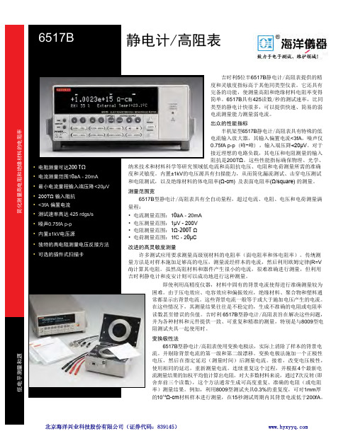
吉时利5位半6517B 静电计/高阻表提供的精度和灵敏度指标高于其他同类型仪表。
它还具有完备的功能,使测量高阻和绝缘材料电阻率变得简单。
6517B 具有425读数/秒的测试速率,比同类型的静电计快很多,可以提供快速、简易的弱电流测量能力测量弱电流。
出众的性能指标半机架型6517B 静电计/高阻表具有特殊的低电流输入放大器,其输入偏置电流<3fA ,噪声仅0.75fA p-p (峰-峰) ,输入端压降<20μV 。
对于接近理想的电路负载,其电压和电阻测量的输入阻抗是200T Ω。
这些性能指标确保物理、光学、(R=V . 6517B 型静电计/高阻表旨在解决这些问题,8009型电4个最新电7次反转(即8009型测试夹具0.3%的重复度,可对1mm 厚15秒测试周期内其背景电流低于200fA 。
(Ω-cm) 及表面电阻率(Ω/square) 的测量。
低电平测量和源静电计/高阻表与数字多用表类似的简单操作6517B 型静电计/高阻表采用与数字多用表类似的简易操作,可通过前面板,利用单一按钮控制电阻测量等重要功能。
还可以通过内置IEEE-488接口实施控制,因此,可利用计算机控制器通过总线对所有功能进行编程。
高精度高阻测量6517B 型静电计/高阻表的诸多特性和能力有助于确保高阻测量应用的准确度。
例如,其内置电压源简化了绝缘器电阻率和所用电源电压电平之间关系的确定。
它还非常适合电容器泄漏和绝缘电阻测量、印刷电路板表面绝缘电阻测试、电阻器电压系数测试以及二极管泄漏特性分析。
温度和湿度测试湿度和温度可能严重影响材料的电阻率值。
为了帮助您准确比较在不同情况下测得的读数,6517B 型静电计/高阻表提供内置K 型热电偶和一个可选的6517-RH 型相对湿度探头。
其内置数据存储缓冲器允许记录和调用具有时间、温度和相对湿度Stamping 的读数。
附件扩展测量能力利用多种可选附件,可以扩展6517B 型静电计/高阻表的应用,并改进其性能。
pl6517a技术规格书

pl6517a技术规格书全文共四篇示例,供您参考第一篇示例:技术规格书是一份非常重要的文件,它详细描述了特定产品或设备的技术参数、性能特点和规格要求,对于产品的设计、制造和应用都有着重要的指导和规范作用。
PL6517A技术规格书就是描述了PL6517A产品的技术参数、性能特点和规格要求的文件。
本文将对PL6517A技术规格书进行详细的介绍和解析。
一、产品概述PL6517A是一款高性能的数字信号处理器,主要用于音频处理和音频信号解码。
它采用了先进的数字信号处理技术,能够实现高效、精确的信号处理和解码,广泛应用于音响设备、汽车音响、智能家居等领域。
产品具有体积小、功耗低、性能稳定等特点,是当前市场上颇受欢迎的音频处理芯片之一。
二、技术参数1. 工作电压:3.3V2. 工作温度:-40℃~85℃3. 输入端口:双通道模拟输入、SPDIF数字输入4. 输出端口:双通道模拟输出、I2S数字输出5. 稳定性:±0.1dB6. 信噪比:120dB7. 总谐波失真:-110dB以上是PL6517A的主要技术参数,从这些参数可以看出,PL6517A具有工作电压低、工作温度范围广、输出稳定性高、信噪比高等优秀的特点,非常适合于高要求的音频处理场景。
三、性能特点1. 高精度信号处理能力:PL6517A内置了先进的数字信号处理算法,能够对音频信号进行高精度的处理和解码,保证了音质的优异性能。
2. 低功耗设计:PL6517A采用了先进的低功耗设计,使得产品在高性能的能够保持较低的功耗水平,有利于节能环保。
3. 稳定可靠:PL6517A使用稳定可靠的硬件和软件设计,经过严格的测试和验证,可以确保产品在各种复杂环境下稳定运行。
四、应用领域PL6517A数字信号处理器适用于多种领域,主要包括但不限于以下几个方面:1. 高端音响设备:PL6517A能够提供高品质的音频处理和解码功能,适用于高端家庭音响、专业音响设备等领域。
肯尼耶伊高压探头和测试线产品说明书

1600A58083706-BAN3381.888.KEITHLEY (U.S. only)A Greater Measure of ConfidenceTest leads and ProbesItem shipped may vary from model p ictured here.Model 1600A High Voltage ProbeMAXIMUM INPUT: 40kV DC or peak AC to 300Hz .INPUT RESISTANCE: 1000M W .DIVISION RATIO: 1000:1 (into 10M W ) .for use with: DMMsModel 1651 50 Ampere Shunt:E xternal 0 .001W ± 1%, 4-terminal shunt; extends current mea s ur i ng capability of Keithley DMMs to 50A .CABLE LENGTH: 1 .4m (56 in) .for use with: DMMsItem shipped may vary from model p ictured here.Model 1681 Clip-On Test Lead Set: Two 1 .2m (48 in) leads terminated with banana plugs and spring action clip-on probes .for use with: DMMsItem shipped may vary from model p ictured here.Model 1751 Safety Test Leads: 91 .4cm (36 in) test lead set supplied with each Model 175A and 197A . Finger guards and shroud e d banana plugs help minimize the chance of making contact with live circuitry .for use with: all DMMs, series 2400 sourceMeter ®sMu InstrumentsA C C E S S O R I E S A Greater Measure of Confidence1.888.KEITHLEY (U.S. only)Test leads and ProbesModel 1752 Premium Safety Test Lead Kit: Includes two banana leads with safety shrouds on both ends, two fully insulated alligator clips, two fully insulated needle probes, and two spring-action clip-on probes with safety blocks, in a carrying case .for use with: all DMMs, series 2400 sourceMeter sMu InstrumentsItem shipped may vary from model p ictured here.Model 1754 Universal Test Lead Kit: 10-piece test lead kit with interchangeable plug-in acces-sories . Kit includes: 1 set of test leads, 91 .4cm (36 in), 1 red and black; 2 spade lugs, 2 standardbanana plugs, 2 hooks, and 2 mini a t ure alligator clips with boots .for use with: all DMMs, series 2400sourceMeter sMu InstrumentsModel 2187-4 Low Thermal Test Lead Kit: Includes an input cable with banana termina-tions, banana extensions, sprung-hook clips, alligator clips, needle probes, and spade lugs to connect the Model 2182A to virtually any DUT . The kit is also used to connect the Model 2182A directly to the Model 622X guard to improve response time for pulsed measure-ments or to reduce errors when measuring high impedance devices .for use with: 2182a, 6220, 6221, 6220/2182a,6221/2182aModel 2600-BAN: 1m (3 .3 ft) banana test leads/adapter cable for a single Series 2600B SourceMeter channel (two needed for use with Model 2602B and 2612B) . Provides safety banana connections to Hi, Sense Hi, Lo, Sense Lo, and guard .for use with: 2601b, 2602b, 2611b, 2612bModel 3706-BAN: 1 .4m (4 .6 ft) banana test leads/adapter cable for Model 3706A mainframe with high performance multimeter option . Provides direct connection to high performance multimeter utilizing rear panel backplane con-nector . Safety banana connections to HI, LO, Sense HI, Sense LO, and AMP .for use with: series 3700a mainframesModel 3706-TLK Test Lead Kit: Includes 3706-BAN banana test leads/adapter cable and plug-in test lead accessories . Test lead accessories include: 4 spring hook probes, 2 needle test probes, 4 safety plug adapters, and carrying case .for use with: series 3700a mainframesT e s t l e a d s a n d p r o b e s1.888.KEITHLEY (U.S. only)A Greater Measure of ConfidenceItem shipped may vary from model p ictured here.Model 5804 Test Lead Set: Designed to be used with Keithley instruments that measure 4-terminal resistance . Contains: 2 test leads, 0 .9m (36 in), red and black; 2 test clips, red and black; 2 plunger clip adapters, red and black; 2 alligator clips with boots (accept standard test probe tip); 2 alligator clips with boots (barrels accept standard banana plugs) .for use with: series 2400 sourceMeter ® sMuInstruments, 2750, DMMsModel 5805 Kelvin Probes: 2 spring-loaded test probes, red and black, 0 .9m (36 in) with bananaplug termination . Des igned to be used with Keithley ins tru m ents that measure 4-terminal re s is t ance and in-circuit current . 1⁄8-in spacing between pin tips . A package of 8 re p lace m ent contacts (P/N CS-551) is available .Model 5805-12: Similar to 5805 but 3 .6m (12 ft) in length .for use with: series 2400 sourceMeter sMuInstruments, 2750, DMMsModel 5806 Kelvin Clip Lead Set: 2 clip test leads, red and black, 0 .9m (36 in) with banana plug ter m i n a t ion . Designed to be used with Keithley instruments that meas u re 4-terminal re s is t ance . Maximum jaw opening ½ in . A package of 8 r eplace m ent elastic bands (P/N 5806-306B) is a vailable .for use with: series 2400 sourceMeter sMuInstruments, 2750, DMMsModel 5807-7 Helical Spring Point Test Leads: Two excellent Kelvin test probes for Keithley in s tru m ents that measure 4-terminal re s is t ance . The probes have point e d tips that rotate when pressure is exerted on the handle . Good contact is assured, and the handle can be held at any angle to the mea s ure m ent surface . The lead wires ter m i n ate in banana plugs . Lead wire length: 2m (7 ft) .for use with: series 2400 sourceMeter sMuInstruments, 2750, DMMsModel 5808 Low Cost, Single Pin, KelvinProbes: Two 1 .17m (46 in) long, single fixed pin probes with source and sense leads per probe and color coded standard safety banana plugs . Designed for applications requiring Kelvin resistance measurements with the convenience of a single point of circuit contact . The Kelvin connection at the base of each probe pin results in very low resistance errors, eliminating all wire and probe body resistance . For the highest preci-sion sensing applications, use the Model 5805, 5806, or 5809 for complete control over sensing point placement .for use with: 2700, 2701, 2750, series 2400,DMMsModel 5809 Low Cost, Kelvin Clip Lead Set: Two 0 .94m (37 in) long probes with alligator style clips, each with opposing blade source and sense connections to color coded standard safety banana plugs . Designed for applications requir-ing Kelvin connection to wires, axial leaded components, and other terminals able to be clipped onto . The miniature blade design accom-modates narrow available width applications as well as general lighter duty applications . The maximum jaw opening is 9 .14mm (0 .36 in) and the blade width is 2 .92mmm (0 .115 in) .for use with: 2700, 2701, 2750, series 2400, DMMsTest leads and ProbesA C C E S S O R I E S341A Greater Measure of Confidence1.888.KEITHLEY (U.S. only)Test leads and ProbesModel 6517-RH Humidity Probe: The 6517-RH comes with a 3m (10 ft) extension cable and is designed to be used with the 6517B Electrom-eter . The 6517-RH measures the relative humidity of the testing environment .OPERATING TEMPERATURE RANGE: –10°C to +60°C OPERATING HUMIDITy RANGE: 0 to 100% RH MEASURING RANGE: 10 to 90% RHTEMPERATURE DEPENDENCE: <±2% from –10°C to +60°Cfor use with: 6517a and 6517b ElectrometersModel 6517-TP Thermocouple Bead Probe: Designed to be used with the 6517B Electro m -eter, the 6517-TP measures the temperature of the testing en v i r on m ent . 6517-TP is 36 in . long and has a temperature calibration (range) of 0°C to 1250°C . Type K thermocouple .for use with: 6517a and 6517b Electrometersand 2110 DMMModel 7401: Type K ther m o c ou p le wire kit includes 30 .5m (100 ft) of type K (chromel-alumel) ther m o c ou p le wire .for use with: 2001-TCsCaN, 2110, 3720, 3721,3724, 7057a, 7700, 7706, 7708Model 8605 High Per f or m ance Modular Test Leads: Highest quality lead with sili c one insula-tion, and removable test probes . Rated to 1500V . UL listed .LENGTH: 1m (3 .3 ft) .for use with: all DMMs, series 2400 sourceMeter ® sMu InstrumentsItem shipped may vary from model p ictured here.Model 8606 High Per f or m ance Modular Probe Kit: For use with Model 8605 High Per-for m ance Modular Test Leads . Contains 2 each spade lugs, alligator clips, and re t ract a ble hooks .for use with: all DMMs; series 2400 and series 2600b sourceMeter sMu Instruments;series 3700aModel 8681 Low Cost RTD: This inexpensive RTD has small size (0 .09 in × 0 .09 in) and fast thermal response time . 100W , 0 .385%/°C ele-ment . Meets or exceeds DIN 43760-1980-A, IEC 751:1983-A, BS1904: 1984-A, and JIS C1604-1981-0 .2 . Can be used with Model 8680 RTD Input Probe Adapter . Measures from –200° to +600°C .LENGTH: 0 .9m (3 ft) .ACCURACy: ±(0 .15°C + 0 .002 × |t|)/°C, where |t| is absolute value of temperature in °C .for use with: 2001, 2002, 2010 DMMs (with 8680), 7700, 7702, 7706, 7708Item shipped may vary from model p ictured here.Model CA-109A Test Lead Set: For output con-nec t ions (two red, two black) .for use with: 2000-sCaN, 2001-sCaN, 2001-TCsCaNT e s t l e a d s a n d p r o b e s1600A58083706-BAN。
示波器使用手册
版权
根据版权法,未经 National Instruments Corporation 事先书面同意,本发行物不得以任何形式 (包括电子或机械形式)进行全
可编程加电状态 .......................................................................................................................................2-3 检测更改.....................................................................................................................................................2-3
DAQ
NI 651x 用户手册
NI PCI-6510、 PCI-6511、 PXI-6511、 PCI-6512、 PXI-6512、 PCI-6513、 PXI-6513、 PCI-6514、 PXI-6514、 PCI-6515、 PXI-6515、 PCI-6516、 PCI-6517、 PCI-6518 和 PCI-6519 设备 NI 651x 用户手册
第1章 NI 651x 基础
NI 651x 配置.............................................................................................................................................1-2 NI 651x 功能概述....................................................................................................................................1-2
KEITHLEY APS-7000系列可编程AC电源说明书
Maximum Current (peak) 0~155Vrms
0~310Vrms
OPT. APS-003 (r.m.s)
0~600Vrms
OPT. 3 (peak)
0~600Vrms
500VA
0 ~ 310.0 Vrms 45.00 ~ 500.0 Hz
4.2A 2.1A 16.8A 8.4A 1.05A@480V 4.2A
The APS-7000 Series comprises nine measurement functions (Vrms, Irms, F, Ipk, W, VA, PF, Ipk hold, CF), and provides user interface similar to that of AC Power Meter. The APS-7000 Series, internal circuit design 4 sets of current range to improve measurement resolution, is ideal for the LED industry and standby mode power consumption test. Under the ARB (function waveform) mode, the APS-7000 Series provides waveforms, including SINE waveform, Triangle waveform, Staircase waveform, Clipped Sinewave, Crest factor waveform, Surge waveform, and Fourier series to meet the requirement of simulating abnormal input power waveform test of different industry.
SN65176BDE4中文资料
PACKAGING INFORMATIONOrderable Device Status(1)PackageType PackageDrawingPins PackageQtyEco Plan(2)Lead/Ball Finish MSL Peak Temp(3)SN65176BD ACTIVE SOIC D875Green(RoHS&no Sb/Br)CU NIPDAU Level-2-260C-1YEARSN65176BDE4ACTIVE SOIC D875Green(RoHS&no Sb/Br)CU NIPDAU Level-2-260C-1YEARSN65176BDG4ACTIVE SOIC D875Green(RoHS&no Sb/Br)CU NIPDAU Level-1-260C-UNLIMSN65176BDR ACTIVE SOIC D82500Green(RoHS&no Sb/Br)CU NIPDAU Level-2-260C-1YEARSN65176BDRE4ACTIVE SOIC D82500Green(RoHS&no Sb/Br)CU NIPDAU Level-2-260C-1YEARSN65176BDRG4ACTIVE SOIC D82500Green(RoHS&no Sb/Br)CU NIPDAU Level-1-260C-UNLIMSN65176BP ACTIVE PDIP P850Pb-Free(RoHS)CU NIPDAU Level-NC-NC-NCSN65176BPE4ACTIVE PDIP P850Pb-Free(RoHS)CU NIPDAU Level-NC-NC-NCSN75176BD ACTIVE SOIC D875Green(RoHS&no Sb/Br)CU NIPDAU Level-2-260C-1YEARSN75176BDE4ACTIVE SOIC D875Green(RoHS&no Sb/Br)CU NIPDAU Level-2-260C-1YEARSN75176BDG4ACTIVE SOIC D875Green(RoHS&no Sb/Br)CU NIPDAU Level-2-260C-1YEARSN75176BDR ACTIVE SOIC D82500Green(RoHS&no Sb/Br)CU NIPDAU Level-2-260C-1YEARSN75176BDRE4ACTIVE SOIC D82500Green(RoHS&no Sb/Br)CU NIPDAU Level-2-260C-1YEARSN75176BDRG4ACTIVE SOIC D82500Green(RoHS&no Sb/Br)CU NIPDAU Level-2-260C-1YEARSN75176BP ACTIVE PDIP P850Pb-Free(RoHS)CU NIPDAU Level-NC-NC-NCSN75176BPE4ACTIVE PDIP P850Pb-Free(RoHS)CU NIPDAU Level-NC-NC-NCSN75176BPSR ACTIVE SO PS82000Green(RoHS&no Sb/Br)CU NIPDAU Level-1-260C-UNLIMSN75176BPSRG4ACTIVE SO PS82000Green(RoHS&no Sb/Br)CU NIPDAU Level-1-260C-UNLIM(1)The marketing status values are defined as follows:ACTIVE:Product device recommended for new designs.LIFEBUY:TI has announced that the device will be discontinued,and a lifetime-buy period is in effect.NRND:Not recommended for new designs.Device is in production to support existing customers,but TI does not recommend using this part in a new design.PREVIEW:Device has been announced but is not in production.Samples may or may not be available.OBSOLETE:TI has discontinued the production of the device.(2)Eco Plan-The planned eco-friendly classification:Pb-Free(RoHS)or Green(RoHS&no Sb/Br)-please check /productcontent for the latest availability information and additional product content details.TBD:The Pb-Free/Green conversion plan has not been defined.Pb-Free(RoHS):TI's terms"Lead-Free"or"Pb-Free"mean semiconductor products that are compatible with the current RoHS requirements for all6substances,including the requirement that lead not exceed0.1%by weight in homogeneous materials.Where designed to be soldered at high temperatures,TI Pb-Free products are suitable for use in specified lead-free processes.Green(RoHS&no Sb/Br):TI defines"Green"to mean Pb-Free(RoHS compatible),and free of Bromine(Br)and Antimony(Sb)based flameretardants(Br or Sb do not exceed0.1%by weight in homogeneous material)(3)MSL,Peak Temp.--The Moisture Sensitivity Level rating according to the JEDEC industry standard classifications,and peak solder temperature.Important Information and Disclaimer:The information provided on this page represents TI's knowledge and belief as of the date that it is provided.TI bases its knowledge and belief on information provided by third parties,and makes no representation or warranty as to the accuracy of such information.Efforts are underway to better integrate information from third parties.TI has taken and continues to take reasonable steps to provide representative and accurate information but may not have conducted destructive testing or chemical analysis on incoming materials and chemicals.TI and TI suppliers consider certain information to be proprietary,and thus CAS numbers and other limited information may not be available for release.In no event shall TI's liability arising out of such information exceed the total purchase price of the TI part(s)at issue in this document sold by TI to Customer on an annual basis.IMPORTANT NOTICETexas Instruments Incorporated and its subsidiaries (TI) reserve the right to make corrections, modifications, enhancements, improvements, and other changes to its products and services at any time and to discontinue any product or service without notice. Customers should obtain the latest relevant information before placing orders and should verify that such information is current and complete. All products are sold subject to TI’s terms and conditions of sale supplied at the time of order acknowledgment.TI warrants performance of its hardware products to the specifications applicable at the time of sale in accordance with TI’s standard warranty. T esting and other quality control techniques are used to the extent TI deems necessary to support this warranty. Except where mandated by government requirements, testing of all parameters of each product is not necessarily performed.TI assumes no liability for applications assistance or customer product design. Customers are responsible for their products and applications using TI components. T o minimize the risks associated with customer products and applications, customers should provide adequate design and operating safeguards.TI does not warrant or represent that any license, either express or implied, is granted under any TI patent right, copyright, mask work right, or other TI intellectual property right relating to any combination, machine, or process in which TI products or services are used. Information published by TI regarding third-party products or services does not constitute a license from TI to use such products or services or a warranty or endorsement thereof. Use of such information may require a license from a third party under the patents or other intellectual property of the third party, or a license from TI under the patents or other intellectual property of TI.Reproduction of information in TI data books or data sheets is permissible only if reproduction is without alteration and is accompanied by all associated warranties, conditions, limitations, and notices. Reproduction of this information with alteration is an unfair and deceptive business practice. TI is not responsible or liable for such altered documentation.Resale of TI products or services with statements different from or beyond the parameters stated by TI for that product or service voids all express and any implied warranties for the associated TI product or service and is an unfair and deceptive business practice. TI is not responsible or liable for any such statements. Following are URLs where you can obtain information on other Texas Instruments products and application solutions:Products ApplicationsAmplifiers Audio /audioData Converters Automotive /automotiveDSP Broadband /broadbandInterface Digital Control /digitalcontrolLogic Military /militaryPower Mgmt Optical Networking /opticalnetwork Microcontrollers Security /securityTelephony /telephonyVideo & Imaging /videoWireless /wirelessMailing Address:Texas InstrumentsPost Office Box 655303 Dallas, Texas 75265Copyright 2005, Texas Instruments Incorporated。
静电计6517
吉时利5½位显示的6517B提供的精度和灵敏度指标是高于其他同类型仪表。
它丰富的功能使测量高阻和绝缘材料电阻率变得简单。
6517B具有425读数/秒的读数率,比同类型的静电计显著的快,可以提供快速、简易的方式测量弱电流。
Model 6517B是一个更新版本,取代了较早型号6517A(1996年推出)。
Model 6517A的应用软件使用SCPI语言命令可以在Model 6517B上不做任何修改的运行。
不过,Model 6517B较Model 6517A 提供了一些有益的改进和升级,其内部备份电池内存缓冲区现在可以存储多达50,000读数,使用户能够记录更长时间的测试结果,并存储更多的数据和读数。
新的Model还可提供至内部缓冲器(高达425 读数/秒的读数率)以及通过IEEE总线至外部存储器的更高读数率(高达400读数/秒的读数率)。
一些连接器的修改已列入解决现代连接和安全要求。
•电阻测量可达1016Ω•电流测量范围1fA-20mA•最小电流量程输入压降<20µV•200TΩ输入阻抗•<3fA偏置电流•高达425rdgs/s•噪声0.75fA p-p•内置±1kV电源•独特的高电阻测量电压反接方法•可选的插件式扫描卡使用静电计进行准确的高电阻测量时要考虑的最重要的问题是什么?使用静电计欧姆计使用静电计欧姆计时,测量准确度会受到各种因素的影响。
以下各段讨论准确地进行高电阻测量时要考虑的最重要的问题。
基本电路配置图2-33示出静电计欧姆计测量电阻(R)的情况。
欧姆计使用内部的电流源和静电计电压表来进行测量。
仪器自动地计算和显示出测量的电阻值。
注意,这种测量方法是两线电阻测量,而使用静电计电压表和外部电流源则可以进行四线测量。
这是因为电流源在仪器内部与电压表相连,不能分开使用。
保护与高源内阻电压测量和电流测量时一样,在高电阻测试连接中使保护技术可以大大降低泄漏电阻的影响,并提高测量的准确度。
- 1、下载文档前请自行甄别文档内容的完整性,平台不提供额外的编辑、内容补充、找答案等附加服务。
- 2、"仅部分预览"的文档,不可在线预览部分如存在完整性等问题,可反馈申请退款(可完整预览的文档不适用该条件!)。
- 3、如文档侵犯您的权益,请联系客服反馈,我们会尽快为您处理(人工客服工作时间:9:00-18:30)。
!"#$%&'()*+,-./0 !"#$%&'()* !"#$%&'()*+,-./ !"#$%&'()*+,#-. ! !" #$%&'()*+ !"#$% !"#$%&'()*+,-./0 !"#$%&'()*+ !"#$%&'()*+,- !. !"#$%&'%( !"#$%&' !"#$%&'()*+,-./0 !"#$%&'( ! !"#$% !"#$%&'()* !"#$%&'( ! !"#$%&'()*+,-./01 ! !"#$%&'()*+ 1000V !"#$ !"#!$%& !" !"#$%&'()* !"#$%&' !"#$%&'()*+,-./012345678'9:; !"#$%&' !"#$%&'()* !"#$%&'()*+,-./0123456'789 !"#$%&'( !"#$%&'()*+, !"#$% !"#$%&'()!*+ !"#$%&' !"#$%&' !"#$% !"#$%&'( Keithley !"#$%&' !"#$%&'()*+,%-./0 ! !"#$%&'()*+,-./01 !"#$%&'()*+, !"#$ Keithley !"#$%&'()* + !"#$%&'()*+,-. Keithley !"#$% !"#$%&' !"#$%&'()*+, !"#$%&' !" !"#$% !"# $#%&' !"#$%&'()*+,-./ ! !"#$%&'( ) !"#$%&'()*+ !"#$%&'()*+,!"#$%&'()*+, /
-25 -150
!"#$ 6517-TP !" 6517-RH !"#
!"#$
!"# 0-100%
!"#$ !" ---100V !"#$ 100V 10mA ! 1000V !" 1000V 1mA ! * !" * ! REL * !"#$ * !"# !$ * !"#$ * IEEE-488 GPIB RS-232 !"#$%& * DDC !"#$%& !"# 617 !"#$%&' * !"# 707A 7001 7002 !"#$%& * !"#$ 6521 6522 !"#$%& 6517A !" 1 2 !"#$%&'()* !"# !"#$%&'()
Keithley Instruments, Inc.
! 28775 Aurora Road . Cleveland, Ohio 44139 . 1-888-KEITHLEY 534-8453 . !"#$%& !"
!" #$%& 18 ! A1301 100088 8610-55010010 82255010 8610-82255018 E-mail:china@
!"#$%&'(
!"#$ 800-810-1334
!"#$
!"# china@
!"
6517A
/
=Å=OMMQ
!"
hÉáíÜäÉó !
!
! SRNT^`JVMPJMN=Rev. B
!
!"( ) !"#$ Getting Started Manual !" !"# 6517A-903-01 Rev. A !"#$%& 6517A-903-01 Rev. B !"#$%&'()*!+ !"#$%&'()*+, ! !"#
: Sint-Pieters-Leeuw
02-363 00 40 Fax: 02-363 00 64 www.keithley.nl
: Tokyo 81-3-5733-7555 Fax: 81-3-5733-7556 www.keithley.jp : Seoul 82-2-574-7778 Fax: 82-2-574-7838 : Gorinchem 0183-635333 Fax: 0183-630821 www.keithley.nl : Singapore 65-6747-9077 Fax: 65-6747-2991 : Solna 08-509 04 600 Fax: 08-655 26 10 : Hsinchu 886-3-572-9077 Fax: 886-3-572-9031
===
!"
1.1 1.2 1.3 1.4 1.5 1.6 1.7 1.8 1.9 1.10 1.11 !" ! ! ! ! !" ! !"#$%!&' !
1
2 6 6 7 7 7 9 10 11 13 14
!
2.1 2.2 2.3 2.4 2.5 2.6 2.7 2.8 2.9 2.10 2.11 2.12 2.13 2.14 2.15 2.16 ! ! ! ! ! !"#$ ! !"#
17
18 20 22 24 25 25 25 28 28 29 31 32 34 35 36 37
!
3.1 3.2 3.3 ! IEEE-488 !
41
42 42 42
3.4 3.5 3.6 3.7 3.8
RS-232 IEEE-488 RS-232 IEEE-488 RS-232 ! !"#$ !"#$
!"#
!"#$%&'()*+,!"#$%&'() !"#$%&'() !"#$%&'( !"#$%&'()*+, !"#$%&'()*+,-./0 !"#$%&'()*+,-./012 !"#$%&'()* !"#$% !"#$%&'()*+ ! ! !"#$%&' !"# !"#$%&'()*+ !"#$%&'()* !"#$% !"#$%&'(#)*+,-. !"#$%&'()*$%+,! !"#$%&'()*+, !"#$%&'()*+ !"#$%&'()*+,-./01234 !" !"#$%&'( !"#$%&'( )* !"#$%&'()* !"#$ !""#$%&'() ! !"#$%&'() !"#$ !% !"#$%&'()* !"#$$%&'()*+'(,-./.0123456 !"#$ ! !"#$%&'()*+,-./01 Keithley !"#$%&'()*+,-. IEC IEC60664 !"#$%& !"#$%&' !"#$ I/O !"#$%&' !"#"$ !"#$%& ' () !"#$%&'()*+,!"#$%& !"#$%&' () !"#$%&'(%) !"# !" I/O ! !"#$% !"#$%&'()* !"#$%&'()*+,-./ 01 !" ANSI !"#$%&'() *+, 30V RMS ! 42.4V !" 60V !"#$%&'( !" !"#$%&'()*+,-&./ !"#$%&'()*+,-./0123 !"#$%&'()*%+, !"#$ !"#$ !"#$% !"#$% !"#$ !" !"#$ !"#$%&' !"#$ 1000V !"# !"#$% !"#$% !"#$%&'&()*+,-../0 !"#$%&'()* !"# !"!#$%&'( !"#$%&'()*+ !" #$ !"#$% !" !"#$% !"#$%&'&()*!+,!"#$ !"#$% !" !"# !"#$%&'() !"#$ !"#$%&'()*+ !"#$ !"#$%&'() !"# ! "#$%&'()*+, !"#$%&'()* !"#$%&'() !"#!$%&' !"#$% !" ! ! !"#$%&'()*+,-./0"12345"6 !"#$%&'( !"# !"#$%& !"#$% !"#$%&' !"#$%&'()*+,-.+/012,3456 !"# !"#$ !"# !"#$%&'()*+