HLK-RM04 SerailWifi DataSheet 串口WIFI
野火WF-HLK-RM04模块数据手册

WF-HLK-RM04数据手册——野火高性能UART-ETH-WIFI模块修订历史日期版本更新内容2014/12/15 1.0.0 -文档说明本手册旨在说明WF-HLK-RM04 WIFI模块的参数、硬件资源,包含原理图、尺寸图等。
关于构建模块开发环境及使用相关的说明请参考《WF-HLK-RM04 用户手册》。
目录WF-HLK-RM04 数据手册 (1)文档说明 (2)目录 (3)1.产品概述 (4)1.1 简介 (4)1.1.1 产品特性 (4)2.模块资源描述 (5)3.模块原理图 (12)4.模块尺寸图 (13)5.产品更新及售后支持 (14)1. 产品概述1.1 简介WF-HLK-RM04是野火设计的一款高性能UART-ETH-WIFI(串口-以太网-无线网)模块。
该模块板载Hi-Link公司的HLK-RM04 模块,已通过FCC,CE 认证,可直接用于产品销往欧美地区,其外观见图 1-1。
图 1-1 WF-HLK-RM04 WiFi模块1.1.1 产品特性WF-HLK-RM04模块的基本特性如表 1-1所示:表 1-1 WF-HLK-RM04模块的基本特性项目说明网络标准无线标准:IEEE 802.11n、IEEE 802.11g、IEEE 802.11b 有线标准:IEEE 802.3、IEEE 802.3u无线传输速率❑11n:最高可达 150Mbps ❑11g:最高可达 54Mbps ❑11b:最高可达 11Mbps信道数1~14频率范围 2.4~2.4835Ghz发射功率12~15DBM网络接口 2 个以太网口(WAN+LAN)电源接口DC005-2.1mm直流电源座通信接口①RS232 串口/LVTTL串口天线外接(IPX 接口)/板载(贴片天线)工作温度-20℃~+70℃工作湿度10%~90%RH(不凝结)外形尺寸76mm*56mm注①:LVTTL串口,通过排针连接,支持 3.3V/5V 系统WF-HLK-RM04模块的功能特性如表 1-2所示:表 1-2 WF-HLK-RM04 模块功能特性功能说明WIFI 工作模式❑无线网卡(WIFI STA)❑无线接入点(WIFI AP)❑无线路由器(WIFI ROUTER)无线安全❑MAC 地址过滤❑无线安全功能开关❑64/128 位 WEP 加密❑WPA-PSK/WPA2-PSK、WPA/WPA2 安全机制WDS 无线桥接支持网络管理❑远程 Web 管理❑配置文件导入导出串口以太网工作模式❑串口转以太网(ETH-COM)❑串口转无线网卡(COM-WIFI STA)❑串口转无线接入点(COM-WIFI AP)串口波特率范围1200~500000bpsTCP 最大连接数≥20UDP 最大连接数≥20固件升级Web 升级WF-HLK-RM04模块的电气特性如表 1-3所示:表 1-3 WF-HLK-RM04 模块电气特性项目说明电源供电DC6-24VIO 电平②Voh(min) 2.4V、Vol(max) 0.4V、Vih(min)2.0V、Vil(max) 0.8V 功耗③50~110mA@12V注②:对于通信接口(即:TXD/RXD/WPS/ES等接口),可以兼容 3.3V/5V 单片机系统。
SE5004L_Datasheet_Rev_1p7
DST-00316 Rev 1.7 Feb-25-2011
Confidential
3 of 10
SE5004L
5 GHz, 26dBm Power Amplifier with Power Detector Preliminary Information
AC Electrical Characteristics
Recommended Operating Conditions
Symbol VCC TCASE_MAX VREF Supply Voltage VCC3 Supply Voltage VCC1, VCC2 Maximum Case Temperature Reference Voltage Parameter Min. 3.0 3.0 -40 2.8 Max. 5.5 VCC3 85 2.9 Unit V °C V
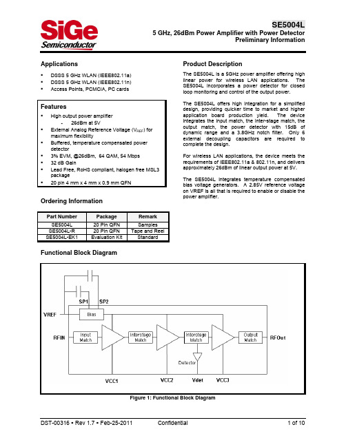
Figure 1: Functional Block Diagram
DST-00316 Rev 1.7 Feb-25-2011
Confidential
1 of 10
SE5004L
5 GHz, 26dBm Power Amplifier with Power Detector Preliminary Information
Figure 2: SE5004L Pin Out (Top View Through Package)
Pin Out Description
Pin No. 1 2 3 4 5 6 7 8 9 10 11,12 13 14-17 18 19 20 Name NU GND RFin GND VREF SP1 SP2 VCC2 VCC3 DET GND RF OUT GND VCC3 VCC2 VCC1 Description Pin is not used, and is open circuit in the package Ground Power Amplifier RF input, DC block required Ground Reference Voltage Port for optional capacitor to improve dynamic EVM Port for optional capacitor to improve dynamic EVM Second Stage Supply Voltage Third Stage Supply Voltage Analog Power Detector Output Ground Power Amplifier RF Output Ground Third Stage Supply Voltage Second Stage Supply Voltage First Stage Supply Voltage
RAK WISCAM 编程手册 V1.0说明书

RAK WISCAM编程手册V1.0深圳瑞科慧联科技有限公司©2015 瑞科慧联保留所有权利本文提到的实际公司和产品的名称是其所有者的商标未经瑞科慧联明确批准,本文档的任何部分均不得转载,存储在任何检索系统中,也不得以任何形式发布本文件如有变更,恕不另行通知目录1串行使用 (1)2 功能介绍 (2)2.1文件传输功能 (3)2.2网络功能 (3)2.3透传功能 (4)2.4远程登录功能 (5)2.5演示 (5)2.6 HTTP命令 (5)3开源清单 (7)4修改记录 (8)1串行使用RAK CAM正常启动debug连接您的电脑和开发板后,配置您的工具,然后单击“连接”。
最后启动开发板,您将看到以下信息。
2 功能介绍该模块包括许多功能:1 tftp:您可以使用tftp发送文件。
2网络:默认情况下只有“接入点”,您可以将其连接到其他路由器。
您可以使用http 命令更改一些配置。
3透明传输:此功能可将“串口数据”更改为“tcp数据”。
4 Telnet:远程登录。
5演示:gpio和音频演示。
6 http命令:命令列表。
2.1文件传输功能通过tftp:1下载“Tftpd”并安装2运行tftpd.exe,选择服务器接口和当前目录3将文件复制到您的目录4在终端输入命令:tftp -r filename -g ip(服务器接口)2.2网络功能将AP更改为STA(将模块连接到路由器)默认情况下,AP启动,并且ssid: WisCam + mac地址密码:12345678IP:192.168.100.1(将模块连接到路由器)通过“list”命令(在接口命令后面),可以看到wifi相关的信息。
配置静态化:静态:静态ip,可以手动设置ip和网关,并通过“list”命令查看ip和网关;DHCP:动态ip,ip地址随机分配,但是通过“list”命令看不到ip和网关,可以连接到串口并通过“ifconfig”命令查看ip地址。
HLK-RM04用户手册1.21
深圳市海凌科电子有限公司 Shenzhen Hi-Link Electronic Co.,Ltd Tel:0755-83575155 Fax:0755-83575189
深圳市海凌科电子有限公司
HLK-RM04 说明书
ETHERNET 以太 WIFI 无线网
3 快速开始向导.................................................................................................... ................................................ 8
全功能串口网络/无线模块
1/45
深圳市海凌科电子有限公司 Shenzhen Hi-Link Electronic Co.,Ltd Tel:0755-83575155 Fax:0755-83575189
1 产品简介.................................................................................................... ........................................................5
6 串口 AT 指令配置.................................................................................................... ....................................... 19
普锐司玛 ORiNOCO Wi-Fi Q2 2020v1 产品指南说明书

Controller ORiNOCO 9100 & Tsunami 10100 specifics
Network statistics RF Management Rogue Devices management (ORiNOCO only)
Included in the Kit One ORiNOCO® AP-9100R with four N-type surge protected connectors One power injector and country specific power cord Two 2.4 GHz, 5 dBi omni antennas Two 5 GHz, 7 dBi omni antennas One full axis Wall / Pole mounting kit One Grounding kit One Connector weatherproofing kit One Quick Installation Guide
One Quick Installation Guide
Anixter Code: 625519
Service options available: ServPak : level 1 (Plus or Prime)
© 2020 PPrrooxximimWWirireelelessss.. AAlllrrigighhttssrreesseerrvveedd..
New PV Advanced V.2.2 includes General
Supports Windows Server 2008(R2), 2012(R2) and 2016 Supports PostgreSQL v9.6.5 Remote client (no need for NPAPI capable web browser) Database quick backup/restore tool New products support
HLK-RM08S 用户手册说明书

HLK-RM08S用户手册5PORT ETHERNET以太网150M WIFI无线网双串口网络/无线模块版本:V1.54日期:2022年10月13日版权所有@深圳市海凌科电子有限公司目录1产品简介 (2)2产品综述 (2)2.1技术规格 (2)2.2硬件说明 (3)3快速开始向导 (7)3.1恢复出厂设置 (7)3.2配置网络参数 (7)3.3配置串口转网络透传参数 (7)4功能说明 (8)4.1默认模式 (8)4.2串口转以太网 (9)5参数配置 (11)5.1参数存储 (11)6WEB页面配置 (12)6.1WEB配置网络 (12)6.3提交更改 (17)7串口AT指令 (17)8串口配置工具 (20)8.1搜索模块 (22)8.2设置各选项参数 (22)8.3提交配置 (23)8.4用户数据保存 (24)8.5查询配置 (24)8.6进入透传模式 (24)8.7恢复出厂设置 (24)9设备搜索工具 (24)10网络AT指令 (25)11恢复设置 (26)附录A文档修订记录 (28)1产品简介HLK-RM08S是海凌科电子新推出的低成本嵌入式UART-ETH-WIFI(串口-以太网-无线网)模块。
本产品是基于通用串行接口的符合网络标准的嵌入式模块,内置TCP/IP协议栈,能够实现用户串口、以太网、无线网(WIFI)3个接口之间的转换。
通过模块,传统的串口设备在不需要更改任何配置的情况下,即可通过Internet网络传输自己的数据。
为用户的串口设备通过网络传输数据提供完整快速的解决方案。
MCU HLK-RM08SSerialWiFiEthernet图 1.功能结构2产品综述2.1技术规格网络参数网络标准无线标准:IEEE802.11n、IEEE802.11g、IEEE802.11b有线标准:IEEE802.3、IEEE802.3u无线传输速率11n:最高可达11g:最高可达11b:最高可达150Mbps54Mbps11Mbps信道数1-11频率范围 2.4-2.4835G发射功率15-20DBM接口5个以太网口、2个串口、1个usb口(host/slave)、GPIO天线天线类型板载天线/外接天线(二选一)功能参数WIFI工作模式无线网卡/无线接入点/无线路由器WDS功能支持WDS无线桥接无线安全无线MAC地址过滤无线安全功能开关64/128/152位WEP加密WPA-PSK/WPA2-PSK、WPA/WPA2安全机制网络管理远程Web管理配置文件导入与导出WEB软件升级串口转网络TCP连接最大连接数>20UDP连接最大连接数>20串口波特率1200~2000000bps其它参数状态指示灯状态指示环境标准工作温度:-40-60℃工作湿度:10%-90%RH(不凝结)存储温度:-40-80℃存储湿度:5%-90%RH(不凝结)其它性能频段带宽可选:20MHz、40MHz,自动2.2硬件说明2.2.1机械尺寸尺寸如下图所示:ES0功能说明:1.系统正常启动后,REF_CLK(11脚GPIO0)保持低电平时间0.05s<t<6s,串口0退出透传模式。
HLK2571WF的说明书

样品承认书SPECIFICATION FOR APPROV ALVersion: 1.8. Page 1 of 41. 简介简介::HLK-2M01 采用4脚插针支持USB2.0接口, 采用2.4GHz ISM 频段,符合IEEE802.11b/g 标准协议的无线模组。
本模组可适应不同的工作环境,使用户方便地接入802.11b/g 无线网络,同时支持无线漫游功能。
标准的USB2.0、1.1接口协议简便了软件开发,另外带固定安装孔、可外接天线的设计尤其适合于需要用到WLAN 无线连接的各种嵌入式系统,诸如:IP 摄像机、机顶盒、媒体播放器、GPS 接收机、数码相框、网络收音机、门禁控制器等,易于整合到机器设备中。
主要性能主要性能::符合IEEE 802.11b/g标准;工作频率范围:2.4~2.4835GHz 智能电源管理,提供可选的简便配置、监控程序工作信道数13,展频技术DSSS(直接序列展频)数据调制BPSK, QPSK, CCK and OFDM(BPSK/QPSK/16-QAM/ 64-QAM)传输速率11b:11/5.5/2/1M(自适应),11g:54/48/36/24/18/12/9/6M(自适应) 最大传输速率:54Mbps, 最大吞吐率:27Mbps提供两种工作模式:集中控制式(Infrastructure)和对等式(Ad-Hoc)一般传输距离:室内最远约100米;室外最远约300米(环境因素对距离有影响),具体看外接天线的增益和安装位置。
2. 规格规格::1)原理框图. Page 3 of 42)常见常见适用平台适用平台操作系统 MCU/CPU 驱动软件 Linux 2.4/2.6 ARM, MIPSII 支持 Windows 2000/XP/Vista X86 平台 支持 Windows CE 5.0/6.0ARM, MIPSII支持3)规格规格参数参数 硬件芯片 雷凌RT2571+RT2528 接口 USB 2.0/1.1, 2.0mm 间距插针 LED 灯 连接/ 激活RF (射频射频)) 天线 通过 I-PEX 接头连接外接天线, 阻抗:50欧姆 频率 2412~2483.5 MHz, ISM 频段., 带宽20MHz. 发射功率 802.11b: 16+/-1.5dBm; 802.11g: 15+/-1.5dBm;接收灵敏度802.11b: -83dBm@11Mbps; 802.11g: -67dBm@54Mbps 软件操作系统 Windows CE/2000/XP/Vista; Linux; Mac OS X 安全机制WEP 64/128 , WPA, WPA2, 802.1X,兼容Cisco CCS V1.0, 2.0 and V3.0工作条件工作电压工作电压、、电流* DC 5.0V ± 5% 、340mA 或 DC 3.3V ± 5% 、200mA 工作温度 0°C - 50°C 储存温度 -20°C - 70°C 工作湿度 RH 95% (非冷凝) 储存湿度RH 95% (非冷凝)机械规格尺寸 19.0*41.0*8.8(针高)mm重量3.8g (含屏蔽盖和插针)4)产品图产品图示示a. 4针公头插针,针脚间距2.0mm.b. 管脚功能定义(注意该定义会随针脚的朝向而不同)c. 天线的接入方式:采用料号为20279-001E-01的I-PEX 座扣接。
Modicon M241 产品数据手册说明书

i s c l a im e r : T h i s d o c u m e n t a t i o n i s n o t i n t e n d e d a s a s u b s t i t u t e f o r a n d i s n o t t o b e u s e d f o r d e t e r m i n i n g s u i t a b i l i t y o r r e l i a b i l i t y o f t h e s e p r o d u c t s f o r s p e c i f i c u s e r a p p l i c a t i o n sProduct datasheetCharacteristicsTM241CE40Tcontroller M241 40 IO transistor PNP EthernetMainRange of productModicon M241Product or component type Logic controller [Us] rated supply voltage 24 V DCDiscrete input number 24 discrete input including 8 fast input conforming to IEC 61131-2 Type 1Discrete output type TransistorDiscrete output number 16 transistor including 4 fast output Discrete output voltage 24 V DC for transistor outputDiscrete output current0.1 A with Q0...Q3 terminal(s) for fast output (PTO mode)0.5 A with Q0...Q15 terminal(s) for transistor outputComplementaryDiscrete I/O number40Number of I/O expansion module 7 (local I/O architecture)14 (remote I/O architecture)Supply voltage limits 20.4...28.8 V Inrush current<= 50 APower consumption in W 32.6...40.4 W with max number of I/O expansion module Discrete input logic Sink or source Discrete input voltage 24 V Discrete input voltage type DCVoltage state1 guaranteed >= 15 V for input Current state 1 guaranteed >= 2.5 mA for input >= 5 mA for fast input Voltage state 0 guaranteed <= 5 V for input Current state 0 guaranteed <= 1 mA for input<= 1.5 mA for fast input Discrete input current 7 mA for input10.7 mA for fast input Input impedance4.7 kOhm for input2.81 kOhm for fast inputResponse time<= 2 µs turn-on operation with I0...I7 terminal(s) for fast input<= 2 µs turn-off operation with I0...I7 terminal(s) for fast input<= 2 µs turn-on operation with Q0...Q3 terminal(s) for fast output<= 2 µs turn-off operation with Q0...Q3 terminal(s) for fast output50 µs turn-on operation with I0...I15 terminal(s) for input50 µs turn-off operation with I0...I15 terminal(s) for input<= 34 µs turn-on operation with Q0...Q15 terminal(s) for output<= 250 µs turn-off operation with Q0...Q15 terminal(s) for outputConfigurable filtering time 1 µs for fast input12 ms for fast input0 ms for input1 ms for input4 ms for input12 ms for inputDiscrete output logic Positive logic (source)Output voltage limits30 V DCCurrent per output common 2 AOutput frequency<= 20 kHz for fast output (PWM mode)<= 100 kHz for fast output (PLS mode)<= 1 kHz for outputAccuracy+/- 0.1 % at 20...100 Hz for fast output+/- 1 % at 100 Hz...1 kHz for fast outputLeakage current<= 5 µA for outputVoltage drop<= 1 VTungsten load<= 2.4 WProtection type Short-circuit and overload protection with automatic resetReverse polarity protection for fast outputShort-circuit protectionReset time10 ms automatic reset output12 s automatic reset fast outputMemory capacity8 MB for program64 MB for system memory RAMData backed up128 MB built-in flash memory for backup of user programsData storage equipment<= 32 GB SD card optionalBattery type BR2032 lithium non-rechargeable, battery life: 4 yrBackup time 2 years at 25 °CExecution time for 1 KInstruction0.3 ms for event and periodic task0.7 ms for other instructionApplication structure8 external event tasks4 cyclic master tasks3 cyclic master tasks + 1 freewheeling task8 event tasksRealtime clock WithClock drift<= 60 s/month at 25 °CPositioning functions PWM/PTO function 4 channel(s) (positioning frequency: 100 kHz)Counting input number 4 fast input (HSC mode)Control signal type A/B signal at 100 kHz for fast input (HSC mode)Pulse/Direction signal at 200 kHz for fast input (HSC mode)Single phase signal at 200 kHz for fast input (HSC mode)Integrated connection type USB port with connector mini B USB 2.0Ethernet with connector RJ45Non isolated serial link "serial 1" with connector RJ45 and interface RS232/RS485Non isolated serial link "serial 2" with connector removable screw terminal block and interface RS485 Supply Serial link supply "serial 1" at 5 V, 200 mATransmission rate 1.2...115.2 kbit/s (115.2 kbit/s by default) for bus length of 15 m - communication protocol: RS4851.2...115.2 kbit/s (115.2 kbit/s by default) for bus length of 3 m - communication protocol: RS232480 Mbit/s for bus length of 3 m - communication protocol: USB10/100 Mbit/s - communication protocol: EthernetCommunication port protocol Modbus non isolated serial link with master/slave methodPort Ethernet 1 - 10BASE-T/100BASE-TX port with copper cable supportCommunication service FDRDownloadingIEC VAR ACCESSMonitoringNGVLProgrammingUpdating firmwareSMS notificationsDHCP server (via TM4 Ethernet switch network module)DHCP client (embedded Ethernet port)SNMP client/serverFTP client/serverSQL clientSend email from the controller based on TCP/UDP libraryModbus TCP client I/O scannerEthernet/IP originator I/O scanner (embedded Ethernet port)Ethernet/IP target, Modbus TCP server and Modbus TCP slaveLocal signalling 1 LED green for SD card access (SD)1 LED red for BAT1 LED green for SL11 LED green for SL21 LED per channel green for I/O state1 LED red for I/O error (I/O)1 LED red for bus fault on TM4 (TM4)1 LED green for Ethernet port activity1 LED red for module error (ERR)1 LED green for PWR1 LED green for RUNElectrical connection Removable screw terminal block for inputs and outputs (pitch 5.08 mm)Removable screw terminal block for connecting the 24 V DC power supply (pitch 5.08 mm) Cable length<= 50 m unshielded cable for input<= 10 m shielded cable for fast input<= 3 m shielded cable for fast output<= 50 m unshielded cable for outputInsulation500 V AC between fast input and internal logicNon-insulated between inputs500 V AC between output and internal logic500 V AC between fast output and internal logicNon-insulated between outputs500 V AC between input and internal logic500 V AC between output groups500 V AC between supply and internal logicNon-insulated between supply and groundMarking CESurge withstand 1 kV for power lines (DC) in common mode conforming to EN/IEC 61000-4-51 kV for shielded cable in common mode conforming to EN/IEC 61000-4-50.5 kV for power lines (DC) in differential mode conforming to EN/IEC 61000-4-51 kV for relay output in differential mode conforming to EN/IEC 61000-4-51 kV for input in common mode conforming to EN/IEC 61000-4-51 kV for transistor output in common mode conforming to EN/IEC 61000-4-5Web services Web serverMaximum number of connections8 connection(s) for Modbus server8 connection(s) for SoMachine protocol10 connection(s) for web server4 connection(s) for FTP server16 connection(s) for Ethernet/IP target8 connection(s) for Modbus clientNumber of slave16 Ethernet/IP64 Modbus TCPCycle time10 ms 16 Ethernet/IP64 ms 64 Modbus TCPMounting support Top hat type TH35-15 rail conforming to IEC 60715Top hat type TH35-7.5 rail conforming to IEC 60715Plate or panel with fixing kitHeight90 mmDepth95 mmWidth190 mmProduct weight0.62 kgEnvironmentStandards CSA C22.2 No 142ANSI/ISA 12-12-01UL 1604CSA C22.2 No 213EN/IEC 61131-2 : 2007Marine specification (LR, ABS, DNV, GL)UL 508Product certificationsCSA cULus RCMIACS E10Resistance to electrostatic discharge 4 kV on contact conforming to EN/IEC 61000-4-28 kV in air conforming to EN/IEC 61000-4-2Resistance to electromagnetic fields10 V/m (80 MHz...1 GHz) conforming to EN/IEC 61000-4-33 V/m (1.4 GHz...2 GHz) conforming to EN/IEC 61000-4-31 V/m (2 GHz...3 GHz) conforming to EN/IEC 61000-4-3Resistance to fast transients2 kV for power lines conforming to EN/IEC 61000-4-41 kV for Ethernet line conforming to EN/IEC 61000-4-41 kV for serial link conforming to EN/IEC 61000-4-41 kV for input conforming to EN/IEC 61000-4-41 kV for transistor output conforming to EN/IEC 61000-4-4Resistance to conducted disturbances,induced by radio frequency fields10 V (0.15...80 MHz) conforming to EN/IEC 61000-4-63 V (0.1...80 MHz) conforming to Marine specification (LR, ABS, DNV, GL)10 V (spot frequency (2, 3, 4, 6.2, 8.2, 12.6, 16.5, 18.8, 22, 25 MHz)) conforming to Marine specification (LR, ABS, DNV, GL)Electromagnetic emissionConducted emissions, test level: 120...69 dBµV/m QP, condition of test: power lines (radio frequency:10...150 kHz) conforming to EN/IEC 55011Conducted emissions, test level: 79...63 dBμV/m QP, condition of test: power lines (radio frequency:150 kHz...1.5 MHz) conforming to EN/IEC 55011Conducted emissions, test level: 63 dBμV/m QP, condition of test: power lines (radio frequency:1.5...30 MHz) conforming to EN/IEC 55011Radiated emissions, test level: 40 dBμV/m QP with class A (radio frequency: 30...230 MHz)conforming to EN/IEC 55011Radiated emissions, test level: 47 dBμV/m QP with class A (radio frequency: 230 MHz...1 GHz)conforming to EN/IEC 55011Immunity to microbreaks10 msAmbient air temperature for operation -10...55 °C for horizontal installation -10...50 °C for vertical installation Ambient air temperature for storage -25...70 °CRelative humidity 10...95 % without condensation in operation 10...95 % without condensation in storage IP degree of protection IP20 with protective cover in place Pollution degree 2Operating altitude 0...2000 m Storage altitude 0...3000 mVibration resistance3.5 mm (vibration frequency: 5...8.4 Hz) on symmetrical rail 3 gn (vibration frequency: 8.4...150 Hz) on symmetrical rail 3.5 mm (vibration frequency:5...8.4 Hz) on panel mounting 3 gn (vibration frequency: 8.4...150 Hz) on panel mounting Shock resistance15 gn for 11 msOffer SustainabilitySustainable offer status Green Premium productRoHS (date code: YYWW)Compliant - since 1330 - Schneider Electric declaration of conformity Schneider Electric declaration of conformity REAChReference not containing SVHC above the threshold Reference not containing SVHC above the threshold Product environmental profileAvailableProduct environmental Product end of life instructionsAvailableEnd of life manualDimensions Drawings DimensionsClearanceMounting PositionAcceptable MountingNOTE: Expansion modules must be mounted above the logic controller.Incorrect MountingDirect Mounting On a Panel Surface Mounting Hole LayoutDigital InputsWiring Diagram(*) :Type T fuse(1) :The COM0, COM1 and COM2 terminals are not connected internally (A) :Sink wiring (positive logic)(B) :Source wiring (negative logic)Fast Input Wiring (I0...I7)Fast Transistor OutputsWiring Diagram(*) :Type T fuse(1)The V0+, V1+, V2+ and V3+ terminals are not connected internally.(2)The V0-, V1-, V2- and V3- terminals are not connected internally.Transistor OutputsWiring Diagram(*) :Type T fuse(1) :The V1+, V2+ and V3+ terminals are not connected internally.(2) :The V1–, V2– and V3– terminals are not connected internally.USB Mini-B ConnectionEthernet Connection to a PC。
- 1、下载文档前请自行甄别文档内容的完整性,平台不提供额外的编辑、内容补充、找答案等附加服务。
- 2、"仅部分预览"的文档,不可在线预览部分如存在完整性等问题,可反馈申请退款(可完整预览的文档不适用该条件!)。
- 3、如文档侵犯您的权益,请联系客服反馈,我们会尽快为您处理(人工客服工作时间:9:00-18:30)。
Overview:module (serial port - Ethernet -Wireless network) developed by Shenzhen Hi-Link Electronic co., Ltd.This product is an embedded module based on the universal serial interface network standard,built-in TCP / IP protocol stack, interface between the onversions.Through the HLK-RM04 module,Provide a quick solution for the user’s serial devices to transfer data via EthernetModule Block DiagramNote:The software support of usb and GPIO will be release laterApplications• WiFi Led Control• WiFi Power Switch• Home and Commercial buildingautomation• OBDII WiFi Diagnose• RFID Data Transfer• Toys and gaming peripherals• Industrial systems• Telemetry• Remote Control1. IntroductionThe HLK-RM04 module provides designers with a ready made component that provides a fully integrated solution for applications, usingthe IEEE802.11 standard in the 2.4-2.5GHz ISM frequency band, including802.11b/g/n and also provides IEEE802.3, can be quickly andeasily included in product designs. The modules integrate all of the RF components required, removing the need to perform expensiveRF design and test. Products can be designed by simply connecting sensors and switches to the module IO pins or uart interface. Themodules use ralink’s chip Wireless Microcontroller, allowing designers to make use of the serial interface to connect with their deviceHence, this module allows designers to bring wireless applications to market in the minimum time with significantly reduceddevelopment effort and cost.This product is an embedded module based on the universal serial interface network standard,built-in TCP / IP protocol stack, enablingthe user serial port, Ethernet, wireless network (wifi) interface between the conversions. Through the HLK-RM04 module, the traditionalserial devices do not need to change any configuration; data can be transmitted through the Internet network. Provide a quick solutionfor the user’s serial devices to transfer data via Ethernet Also the HLK-RM04 module have FCC modular approvals and is compliant withEU regulations.2. SpecificationsThe parameters are defined here.VDD=5.0V @ +25°CTypical DC Characteristics NotesOnly wifi current ~140mA Wifi to serial,AP mode or Client modeOne rj45 current ~120mA Serial to RJ45.Two rj45 cuurent ~135mA One is Wan anther is LANWiFi and two rj45 ~160mA Default Mode/Factory ModeCentre frequency accuracy +/-25ppm Additional +/-15ppm allowanceTypical RF Characteristics NotesReceive sensitivity -70dBm(802.11n) Use Iqview to adjustMaximum Transmit power 18dBm/15dBm/13.5dBm 802.11b/g/nRF Port impedance – Ipex onnector 50 ohm 2.4 - 2.5GHzVSWR (max) 2:1 2.4 - 2.5GHzCentre frequency accuracy +/-25ppm Additional +/-15ppm allowancePeripherals Notes1200-500kbps UART 2pinsRJ45(WAN) 4pinspppoeSupportdhcpRJ45(LAN) 4pinsSupport3.3V Out 1pins Suuport atmost 300mA/3.3V1.8V Out 1pins Suuport atmost 300mA/1.8V3. Product DevelopmentHi-Link supplies all the development tools needed to enable end-product development to occur quickly and efficiently. These are all freely available from . A evaluation kits is also available, allowing products to be quickly bread boarded. Efficient development of software applications is enabled by the provision of a complete, unlimited, software developer kit.This package provides everything required to develop application code and to trial it with hardware representative of the final module.4. Pin ConfigurationsFigure 1: Pin Configuration (top view)VCC5V GND WIFILED VO3.3 LINK1 N/A VCC5V VO1.8 GPIO5 WPS_RST GPIO4 LINK2 GPIO3 UART_TX UART_RX GPIO2 TXOP2 TXON2 RXIP1 RXIN1N/A GPIO0 GPIO1 ES/RST TXOP1 TXON1 RXIP2 RXIN24.1. Pin AssignmentPin No Signal Type Description1 VCC5V Supply Voltage, 5V+/-10%2 GND Analogue Ground3 WIFILED WLAN Activity LED4 VO3.3 3.3V Output (Suuport Atmost 300mA)5 LINK1 10/100 PHY Port #1 activity LED6 N/A Reserved7 N/A Reserved8 GPIO0 General GPIO Reserved9 GPIO1 General GPIO Reserved10 ES/RST Exit transparent transmission mode/Restore factory value11 TXOP1 10/100 PHY Port #1 TXP12 TXON1 10/100 PHY Port #1 TXN13 RXIP2 10/100 PHY Port #2 TXP14 RXIN2 10/100 PHY Port #2 TXN15 RXIN1 10/100 PHY Port #1 RXN16 RXIP1 10/100 PHY Port #1 RXP17 TXON2 10/100 PHY Port #2 OXN18 TXOP2 10/100 PHY Port #2 OXP19 GPIO2 General GPIO Reserved20 UART_RX UART RXD.21 UART_TX UART TXD.22 GPIO3 General GPIO Reserved23 LINK2 10/100 PHY Port #2 activity LED24 GPIO4 General GPIO Reserved25 WPS/RST WiFi Protected Setup /Restore factory value26 GPIO5 General GPIO Reserved27 VO1.8 1.8V Output (Suuport Atmost 300mA)28 VCC5V Supply Voltage, 5V+/-10%5. Electrical CharacteristicsExceeding these conditions will result in damage to the deviceParameter Min Max Module supply voltage VCC 3.9V 5.5V Module Voltage Output VO3.3 3.1V 3.5 Module Voltage Output VO1.8 1.65V 1.9 GPIO Voltage 3.1V 3.5V Storage temperature -40ºC 95ºC6. Outline Drawing7. Typical Application Circuit7.1 Serial To WiFi7.2 Serial To RJ457.3 Wireless Router with Serial port(Default Mode)Appendix DisclaimersThe contents of this document are subject to change without notice. Hi-Link reserves the right to make changes, without notice, in the products, including circuits and/or software, described or contained therein. Information contained in this document regarding device applications and the like is intended through suggestion only and may be superseded by updates. It is your responsibility to ensure that your application meets with your specifications.Hi-Link warrants performance of its hardware products to the specifications applicable at the time of sale in accordance with Hi-Link’s standard warranty. Testing and other quality control techniques are used to the extent Hi-Link deems necessary to support this warranty. Except where mandatory by government requirements, testing of all parameters of each product is not necessarily performed.Hi-Link assumes no responsibility or liability for the use of any of these products, conveys no license or title under any patent, copyright, or mask work right to these products, and makes no representations or warranties that these products are free from patent, copyright, or mask work infringement, unless otherwise specified.Hi-Link products are not intended for use in life support systems, appliances or systems where malfunction of these products can reasonably be expected to result in personal injury, death or severe property or environmental damage. Hi-Link customers using orselling these products for use in such applications do so at their own risk and agree to fully indemnify Hi-Link for any damages resultingfrom such use.All products are sold subject to Hi-Link 's terms and conditions of sale supplied at the time of order acknowledgment. All trademarks are the property of their respective owners.。