F503恒流二极管
FSFR2100

LVCCUV+ LVCCUVLVCCUVH HVCCUV+ HVCCUVHVCCUVH
LVCC 电源欠压正向阈值(LVCC 启动) LVCC 电源欠压负向阈值(LVCC 停止) LVCC 电源欠压滞回 HVCC 电源欠压正向阈值(HVCC 启动) HVCC 电源欠压负向阈值(HVCC 停止) HVCC 电源欠压滞回
Normalized at 25OC
1.1
1.05
1
0.95
0.9 -50
-25
0
25
50
75
100
Temp (OC)
图 5. 开关频率与温度的关系
1.1
1.05
1
0.95
0.9
-50
-25
0
25
50
Temp (OC)
75
100
图 7. 高侧 VCC (HVCC) 停止与温度的关系
1.1
1.05
1
0.95
应用
等离子(PDP)与液晶(LCD)电视 台式计算机与服务器 适配器 通信电源 音响电源
说明
FSFR2100 是高度集成的电源开关,专为高效率半桥谐振 转换器而设计。FSFR2100 系列具有构建可靠而鲁棒的半 桥谐振转换器所需的一切特性,可以简化设计、提高生产 力、改进性能。FSFR2100 将功率 MOSFET 与快速恢复 型体二极管、高侧栅极驱动电路、精确电流控制的振荡 器、频率限制电路、软启动和内置保护功能整合在一起。 高侧栅极驱动电路具有共模噪声消除能力,通过卓越的抗 噪能力确保运行稳定。MOSFET 的快速恢复体二极管可 以提高异常工作条件下的可靠性,同时又能将反向恢复的 影响降至最低。使用零电压开关 (ZVS) 技术可显著降低开 关损耗并提高效率。ZVS 还可显著降低开关噪声,允许使 用小尺寸的电磁干扰 (EMI) 滤波器。
REF5025A资料

Junction Temperature (TJ max)
ESD Rating
Human Body Model (HBM) Charged Device Model (CDM)
REF50xx +18 30
–55 to +125 –55 to +150
+150 3000 1000
UNIT V mA °C °C °C V V
(1) Stresses above these ratings may cause permanent damage. Exposure to absolute maximum conditions for extended periods may degrade device reliability. These are stress ratings only, and functional operation of the device at these or any other conditions beyond those specified is not implied.
(2) MSOP-8 (DGK) package available Q3, 2007.
ABSOLUTE MAXIMUM RATINGS(1)
PARAMETER
Input Voltage
Output Short-Circuit
Operating Temperature Range
Storage Temperature Range
PARAMETER
OUTPUT VOLTAGE Output Voltage Initial Accuracy: High-Grade
Standard-Grade NOISE Output Voltage Noise
sf53二极管参数

sf53二极管参数SF53二极管参数SF53是一种高效率的二极管,具备多种优秀的特性和参数。
本文将详细介绍SF53二极管的参数,帮助读者更好地了解和应用该器件。
1. 额定电流(Rated Current)SF53二极管的额定电流指的是在标准工作条件下,能够稳定通过的电流值。
对于SF53而言,其额定电流一般为5A。
这意味着在正常工作情况下,该二极管能够承受并稳定通过5A的电流。
2. 额定反向电压(Reverse Voltage)SF53二极管的额定反向电压是指在正常工作条件下,能够安全承受的最大反向电压值。
对于SF53而言,其额定反向电压一般为400V。
这意味着在正常工作情况下,该二极管的反向电压不应超过400V,否则可能会损坏器件。
3. 瞬态功率(Peak Power)SF53二极管的瞬态功率是指在短暂时间内能够承受的最大功率值。
对于SF53而言,其瞬态功率一般为1500W。
这意味着在短时间内,该二极管能够承受1500W的功率,超过该功率可能会导致器件损坏。
4. 正向压降(Forward Voltage Drop)SF53二极管的正向压降是指在正常工作条件下,电流通过时二极管的电压降。
对于SF53而言,其正向压降一般为0.55V。
这意味着在正常工作情况下,该二极管的电压降为0.55V。
5. 反向漏电流(Reverse Leakage Current)SF53二极管的反向漏电流是指在额定反向电压下,二极管反向导通时的漏电流。
对于SF53而言,其反向漏电流一般为5μA。
这意味着在额定反向电压下,该二极管的漏电流为5微安。
6. 反向恢复时间(Reverse Recovery Time)SF53二极管的反向恢复时间是指当二极管由正向导通状态切换到反向截止状态时所需的时间。
对于SF53而言,其反向恢复时间一般为50ns。
这意味着该二极管在从正向导通到反向截止的切换过程中,所需的时间为50纳秒。
7. 工作温度(Operating Temperature)SF53二极管的工作温度是指能够正常工作的温度范围。
1n5399二极管整流参数

1N5399二极管是一种具有极性的整流二极管,其主要参数如下:
1. 最大平均整流电流IF:1N5399二极管允许通过的最大正向平均电流为1.5A。
2. 最高反向工作电压VR:1N5399二极管两端允许施加的最大反向电压为1000V。
3. 最大反向电流IR:在最高反向工作电压下,1N5399二极管允许流过的最大反向电流为1000V。
4. 工作频率fm:1N5399二极管在正常情况下的工作频率为3kHz。
5. 反向恢复时间tre:在规定的负载、正向电流及最大反向瞬态电压下,1N5399二极管的反向恢复时间为tre。
6. 零偏压电容CO:1N5399二极管两端电压为零时,扩散电容及结电容的容量之和为CO。
需要注意的是,1N5399二极管是一种具有极性的二极管,使用时应正确接线,以免出现误操作导致元件损坏。
其引脚配置符号图如下所示:阳极(长引脚)和阴极(短引脚)。
恒流二极管选型表及应用电路

2
RD 东莞市瑞得电子工程有限公司
广东省东莞市东城区东城南路8号楼3楼 H/P:13532456800 QQ::821684988 E-mail:hk200809@
应用电路
1.LED驱动(交流电路) 特点:线路简单,比起限流电阻电路功耗更低,稳定性及效率更高,发光更稳定
LED点灯回路的设计,决定连接串联LED灯的数量。
100
S-562T
F-562
E-562
5.6
5.00~6.50 -0.25~-0.53
100
S-822T S-103T S-123T S-153T S-183T 类别
F-822 F-103 F-123 F-153 F-183 型号
E-822 E-103 E-123 E-153 E-183 封装
8.2 10 12 15 18 输入电压
应用领域/特点
NSI50010YT1G SOD-1 Nhomakorabea38-12mA
50V
NSI45015WT1G SOD-123
15mA±20%
45V
NSI45020AT1G SOD-123
恒流 NSI45025AT1G SOD-123 二极管 NSI45025AZT1G SOT-223 (CCR)
NSI45030AT1G SOD-123
2.LED驱动(直流电路)
3.LED驱动(可调光控制)
4.同一电流值的CRD并联使用,得到倍流的效果。此时恒流管的开启电压为最大的开启 电压,动态电阻相对减小。
/
3
D0-41封装 为直插1W; D0-15封装 为直插1.5W TO-252封装 为贴片2.5W; SOT223封装 为贴片1.4W
S方型
二极管封装大全
军用电子器件目录JUN YONG DIAN ZI QI JIAN MU LU(2005年版)济南半一电子有限公司目录半导体器件选用注意事项 (1)第一部分:二极管 (8)一. 开关二极管 (8)1. 锗金键开关二极管2AK1~20系列 (8)2. 锗金键检波二极管2AP1~31B系列 (9)3. 肖特基检波二极管SP1~31B系列(替代2AP1~31B) (10)4. 肖特基开关二极管SK1~20系列(替代2AK1~20) (11)5. 肖特基开关检波二极管2DKOlO、020、O3O型(替代2AK1~20、2AP1~31B)··126. 硅开关二极管2CK70~86、2CK49~56系列 (13)7. 硅开关二极管1N、1S、1SS、BAV系列 (16)8. 玻璃钝化封装大电流开关二极管RG0.5~5系列 (17)二. 整流二极管 (18)1. 玻封快速硅整流二极管2CZ50~57系列 (18)2. 玻璃钝化整流管1N、RL、6A系列 (19)3. 玻璃钝化高速整流管SF11G~66G系列 (20)4. 贴片玻璃钝化整流管S1~5系列 (21)5. 贴片高速整流管ES1~5系列 (22)6. 肖特基二极管SR0620~510、1N5817~5822系列 (23)7. 肖特基二极管SR735~4060系列 (24)8. 贴片肖特基二极管SS1~36、SS110系列 (25)三. 电压调整(稳压)二极管 (26)1. 硅稳压二极管2CW50~78系列 (26)2. 硅稳压二极管2CW100~121系列 (27)3. 硅稳压二极管ZW50~78系列 (28)4. 硅稳压二极管ZW100~121系列 (29)5. 硅稳压二极管2CW5221~5255(1N5221~5255)系列 (30)6. 硅稳压二极管2CW4728A~4754A(1N4728A~4754A)系列 (31)7. 硅稳压二极管1N746A~759A、1N957A~974A系列 (32)8. 硅稳压二极管1N4352B~4358B系列 (33)9. 硅稳压二极管HZ2~36系列 (34)10. 硅稳压二极管BZX55/C系列 (35)11. 硅稳压二极管BZX85/C系列 (36)四. 电压基准二极管 (37)1. 硅基准稳压二极管2DW14~18系列 (37)2. 硅平面温度补偿二极管2DW230~236系列 (38)五. 电流调整(稳流)二极管 (39)1. 稳流管2DH1~36系列 (39)六. 瞬变电压抑制二极管 (40)1. 单双向瞬变电压抑制二极管TVS500~534系列 (40)2. 单双向瞬变电压抑制二极管TVS1000~1034系列 (41)3. 单双向瞬变电压抑制二极管TVS1500~1534系列 (42)4. 单双向瞬变电压抑制二极管TVS5000~5034系列 (43)第二部分:晶体管 (44)一. 双极型晶体管 (44)1. 硅NPN型平面高频小功率三极管3DG110、3DG111、3DG130系列 (44)2. 硅NPN型外延平面高反压三极管3DG182系列 (45)3. 硅NPN型平面三极管3DK101、3DK106、3DK21系列 (46)4. 硅PNP型外延平面高频小功率三极管3CG111、3CG120、3CG130系列 (47)5. 硅PNP型外延平面高频小功率三极管3CK2、3CK120、3CK130系列 (48)6. 硅PNP型外延平面高频高反压小功率三极管3CG182、3CG184、2N2907系列 (49)7. 硅NPN低频大功率晶体管3DD1~8系列 (50)8. 硅NPN达林顿功率晶体管FH6~8系列 (53)二. 场效应晶体管 (54)1. N沟道MOS型场效应晶体管IRF120~823系列 (54)2. P沟道MOS型场效应晶体管IRF9130~9643系列 (56)3. N沟道结型场效应晶体管3DJ2、3DJ6/66、3DJ7/67/304、3DJ8/68系列 (57)三. 部分替代俄型号晶体管 (59)第三部分:半导体分立器件组件 (60)一. 说明 (60)二. 产品型号 (61)1. 200mA~2A玻璃钝化芯片整流桥DF、1W、RB、W系列 (61)2. 1~4A玻璃钝化芯片整流桥2W、GBP、GBL系列 (62)3. 4~15A玻璃钝化芯片整流桥GBU、GBP系列 (63)4. 15~35A玻璃钝化芯片整流桥GBPC系列 (64)5. 定制式三相整流桥 (65)6. 2Д906A型硅二极管矩阵 (65)7. 双向限幅器SXF0.25~5.8系列 (65)第四部分:电路及模块 (66)一. 集成稳压器 (66)1. 固定输出三端正稳压器CW7800系列 (66)2. 固定输出三端负稳压器CW7900系列 (66)3. 可调输出三端正稳压器CW117系列 (67)4. 可调输出三端负稳压器CW137系列 (67)5. 定制式5V以下电压基准DCW系列 (68)第五部分:外形图 (69)半导体器件选用注意事项半导体器件(以下简称器件)的质量问题,不仅有器件本身所固有的质量和可靠性问题,也有由于用户选择或使用不当造成的器件失效问题。
常用场效应管(25N120等)参数及代换
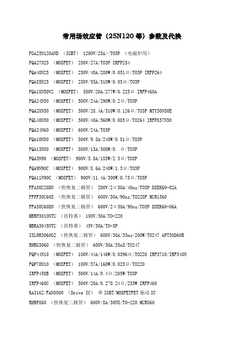
常用场效应管(25N120等)参数及代换FGA25N120AND (IGBT) 1200V/25A//TO3P (电磁炉用)FQA27N25 (MOSFET) 250V/27A/TO3P IRFP254FQA40N25 (MOSFET) 250V/40A/280W/0.051Ω/TO3P IRFP264FQA55N25 (MOSFET) 250V/55A/310W/0.03Ω/TO3PFQA18N50V2 (MOSFET) 500V/20A/277W/0.225Ω IRFP460AFQA24N50 (MOSFET) 500V/24A/290W/0.2Ω/TO3PFQA28N50 (MOSFET) 500V/28.4A/310W/0.126Ω/TO3P MTY30N50EFQL40N50 (MOSFET) 500V/40A/560W/0.085Ω/TO264 IRFPS37N50FQA24N60 (MOSFET) 600V/24A/TO3PFQA10N80 (MOSFET) 800V/9.8A/240W/0.81Ω/TO3PFQA13N80 (MOSFET) 800V/13A/300W/0. Ω/TO3PFQA5N90 (MOSFET) 900V/5.8A/185W/2.3Ω/TO3PFQA9N90C (MOSFET) 900V/8.6A/240W/1.3Ω/TO3PFQA11N90C (MOSFET) 900V/11.4A/300W/0.75Ω/TO3PFFA30U20DN (快恢复二极管) 200V/2×30A/40ns/TO3P DSEK60-02A FFPF30U60S (快恢复二极管) 600V/30A/90ns/TO220F MUR1560FFA30U60DN (快恢复二极管) 600V/2×30A/90ns/TO3P DSEK60-06A MBRP3010NTU (肖特基) 100V/30A/TO-220MBRA3045NTU (肖特基) 45V/30A/TO-3PISL9R3060G2 (快恢复二极管) 600V/30A/35ns/200W/TO247 APT30D60B RHRG3060 (快恢复二极管) 600V/30A/35nS/TO247FQP44N10 (MOSFET) 100V/44A/146W/0.0396Ω/TO220 IRF3710/IRF540N FQP70N10 (MOSFET) 100V/57A/160W/0.025Ω/TO220IRFP450B (MOSFET) 500V/14A/0.4Ω/205W/TO3PIRFP460C (MOSFET) 500V/20A/0.2~0.24Ω/235W IRFP460KA3162/FAN8800 (Drive IC)单IGBT/MOSFETFET驱动ICRHRP860 (快恢复二极管) 600V/8A/30NS/TO-220 MUR860RHRP1560 (快恢复二极管) 600V/15A/TO0220 MUR1560RHRP8120 (快恢复二极管) 1200V/8A/75W/TO220RHRP15120 (快恢复二极管) 1200V/15A/TO220RHRP30120 (快恢复二极管) 1200V/30A/125W/TO220单 DSEI20-10ARHRG30120 (快恢复二极管) 1200V/30A/T03PSSH45N20B (MOSFET) 200V/45A/TO3P IRFP260FGL40N150D (IGBT) 1500V/40A/TO264快速IGBTFGL60N100BNTD (IGBT) 1000V/60A/TO264快速IGBT 1MBH60-100HGTG10N120BND (IGBT) 1200V/35A/298W/100ns/TO247HGTG11N120CND (IGBT) 1200V/43A/298W/TO247HGTG18N120BND (IGBT) 1200V/54A/390W/90ns/TO247FQP5N50C (MOSFET) 500V/5A/73W/1.4Ω/TO-220 替代:IRF830,用于35W FQPF5N50C (MOSFET) 500V/5A/38W/1.4Ω/TO-220F 替代:IRF830,用于35W FQP9N50C (MOSFET) 500V/9A/135W/0.6Ω/TO220 替代:IRF840,用于75W FQPF9N50C (MOSFET) 500V/9A/44W/0.6Ω/TO-220F 替代:IRF840,用于75W FQP13N50 (MOSFET) 500V/13.4A/190W/0.43Ω/TO220 用于75W/125W产品FQPF13N50 (MOSFET) 500V/13.4A/48W/0.43Ω/TO220F 用于75W/125W产品FQD5N50C (MOSFET) 500V/5A/1.4Ω/TO252 用于35WFQA16N50 (MOSFET) 500V/16A/200W/0.32C/TO3P 用于150W到250W的产品FDP15N50 (MOSFET) 500V/15A/0.43Ω/56W/TO220 用于150W左右的产品FQP18N50V2 (MOSFET) 500V/18A/0.43Ω/208W/TO220 用于250WG到400W的产品FQPF18N50V2 (MOSFET) 500V/18A/0.43Ω/56W/TO220 用于250WG到400W的产品FQA18N50V2 (MOSFET) 500V/20A/277W/0.225Ω/TO3P 用于250WG到400W的产品FQA24N50 (MOSFET) 500V/24A/290W/0.2Ω/TO3P 用于400W的产品FQA24N60 (MOSFET) 600V/23.5A/310W/0.24Ω/TO3P 用于400W的产品FQA28N50 (MOSFET) 500V/28.4A/310W/0.126Ω/TO3P 用于400W的产品FQL40N50 (MOSFET) 500V/40A/560W/0.085Ω/TO264 用于560W的产品IRF740B (MOSFET) 400V/10A/0.55Ω/134W/TO220IRF730B (MOSFET) 400V/5.5A/1.0Ω/73W/TO220IRF830B (MOSFET) 500V/4.5A/1.5Ω/73W/TO220 IRF840B (MOSFET) 500V/8A/0.85Ω/134W/TO220 IRFP450B (MOSFET) 500V/14A/0.4Ω/205W/TO3P IRFP460C (MOSFET) 500V/20A/0.2~0.24Ω/235W FQPF5N60C (MOSFET) 600V/5A/TO220FFQPF8N60C (MOSFET) 600V/8A/TO220FFQPF10N60C (MOSFET) 600V/10A/TO220FQPF12N60 (MOSFET) 600V/12A/51W/0.65Ω/TO220F FCP11N60 (MOSFET) 650V/11A/125W0.32Ω/TO220 RHRD660S (快恢复二极管) 600V/6A/TO-252RHRP860 (快恢复二极管) 600V/8A/75W/TO-220 RHRP1560 (快恢复二极管) 600V/15A/TO-220单2N7002 (三极管) 60V/0.12A/SOT-23HUF76629D3S (MOSFET) 100V/20A/110W/TO-252 HUF75639S3S (MOSFET) 100V/56A/200W/TO-263ISL9V3040D3S (IGBT) 430V/21A/150W/300MJ/TO252 ISL9V3040S3S (IGBT) 430V/21A/150W/300MJ/TO263 ISL9V5036S3S (IGBT) 360V/46A/250W/TO262FQP33N10L (MOSFET) 100V/33A/52MΩ127W/TO220。
品牌 F-03-002 型号 Rev AA 产品 操作和维护说明书
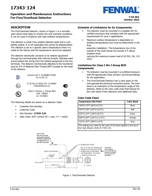
F-03-002October 2016F-03-002Rev AA17343-124Operation and Maintenance Instructions For Fire/Overheat DetectorDESCRIPTIONThe Fire/Overheat Detector, shown in Figure 1 is a normally open device that helps to monitor fire and overheat conditions. It can be used in locations with high ambient temperatures.The detector is made from welded stainless steel and is com-pletely sealed. It is not repairable and cannot be disassembled. The detector is set to a specific alarm temperature when it is made at the factory and the temperature cannot be adjusted.The detector electrically connects to its related equipmentthrough two terminal posts with internal threads. Stainless steel screws attach the wiring from the related equipment to the two terminals. The detector mechanically attaches to the monitored area by 3/4-14 National Pipe Thread (NPT) located on the head of the detector.The following details are shown on a detector head:•Customer Part Number •Customer Code•Part Number: 17343-124•Date Code: XXYY (where XX = year, YY = week)Schedule of Limitations for Ex Components:•The detector must be mounted in a suitably IEC Ex certified enclosure that complies with the appropriate requirements for zone 2 applications.•Maximum surface temperature is dependent onambient temperatures and must be determined in the finalassembly installation. The temperature rise of the outside of the shell should not exceed 2°C above ambient whencarrying the maximum power load of 62.5W (.5A, 125 VDC).Limitations for Class I Div I Group BCD Components:•The detector must be mounted in a certified enclosure with the appropriate Class, Division, and Group Ratings for the application.•The Fire/Overheat Detector has a color band on the end opposite the electrical connection points. The color band is an indication of the temperature range of the detector. Refer to the color code chart that follows for the color band of the detectors and additional data.Color Code ChartII 3G IIC Gc IECEx ETL 12.0008UITS03ATEX41211UClass I, Division 1, Groups BCDCSA: 159064UL: E139663Korean Cert # 14-KB4BO-0749UEx nC IIC T3Temperature Set-Point Color Band140°F±7.5°F (60°C±4.2°C)None 325°F±10°F (163°C±5.6°C)Red 425°F±15°F (218°C±8.3°C)Green 600°F±20°F (316°C±11.0°C)Orange 725°F±25°F (385°C±14°C)GreyThe settings are noted by the color of the band applied to the tip ofthe heat detector shell of 17343-124.NO. 8-32 UNC-2A STAINLESS STEEL SLOTTED HEX HEAD SCREW WITH INTEGRAL LOCKWASHER, 2 PLACES.3/4-14 NPTSTAINLESS STEELDATA LOCATIONSCOLOR CODEPROTECTION CAP.618 ±.0063.500 ±0.315.808 ±.0651.125the NPT threadsFigure 1. Fire/Overheat DetectorOctober 2016F-03-002 Rev AA2Specified data for the Fire/Overheat Detector is given in the table below .INSTALLATIONThis section gives the procedure to install the fire overheat detector .The fire/overheat detector must be attached to an IP 54 suitable/rated junction box with the applicable EquipmentGroup II and Category 3 for the installation. The box must have a 3/4 NPT opening to install the detector .The installer of the detector must supply a means to prevent non-permitted decrease of clearance per IEC60079-15, para-graph 6.7.Replacement parts must be the same part number as the part being replaced.Fastening of the fire detector is through the 3/4 NPT thread. Do not use any anti-seize thread locking compound or lubricant on the NPT threads. The installer must ensure that a proper ground connection is made to the IP 54 box-grounding termi-nal.Procedure1.Turn the detector clockwise into the related equipment’s 3/4 NPT opening a minimum of 5 full turns. Torque the detector to 20 lbf ft (27 Nm).2.Connect the related equipment’s system wiring to the detectors terminals with the No. 8-32 UNC-2A SS slotted hex head screws with integral washer . Make sure the wire connections do not touch each other . Torque the screws to a value between 20 and 25 lbf in. (2.26 and 2.82 Nm).3.Make sure that no objects touch the detector or can touch or damage it during usual system operation.4.Keep the detector free of contamination and unwanted materials. Refer to the Cleaning section.OPERATIONThe Fire/Overheat Detector’s outer shell is made of stainless steel that expands with an increase in temperature. It closely follows changes in the air temperature that surround it. Two inner struts, made of an alloy that expands at a lower rate than the outer shell, are sealed inside the outer shell. An overheat condition causes the shell to expand faster than the innerstruts. This makes the struts move together and make electrical connection through the contacts that are attached to the struts . The electrical connection of the contacts completes the circuit through the terminal posts on the end of the detector . Figure 2 shows a simplified diagram of the Fire/Overheat Detector oper-ation. When the shell and inner struts cool, the contacts open again.There are three conditions that can have an effect on the oper-ation of the detector , especially when a functional test of the detector is done. These conditions are:1.Temperature Overshoot: This condition can occur when the temperature of a detector increases far above its set-point range when heat is supplied too rapidly. This can cause the contacts to close before the specified tempera-ture range.2.Anticipation Effect: This condition causes the alarm circuit to close well before the alarm set-point. This condition is the result of the supply of high heat too rapidly.3.Temperature Undershoot: This condition occurs when the temperature of a detector decreases suddenly below its set-point range when made to cool too rapidly. The detec-tor should be air cool only.If possible, these conditions must be prevented, specially when tests of the detector are done.Figure 2. Detector Simplified DiagramSpecified Item or Function DataTemperature Range for Operation -50°F to +825°F (-45.5°C to +440.5°C)Electrical ContactRating 0.5 Ampere at 125VDCElectrical InterfaceConnection 2 each terminal posts with No. 8-32 UNC-2A Stainless Steel Slotted Hex HeadScrews with Integral LockwasherElectrical ConnectionTorque 25 lbf in. (2.8 Nm) maximum Electrical Connection Protection CapP/N RCL-10 (Vendor: Protective Closures Co., CAGE Code 99017)Dimensions See Figure 1ApprovalATEX approved for Zone 2, Category 3.Type of protection “nC”.Do not supply more than 25 lbf in. torque to the detector’s terminal screws or you can dam-age the detector . If the detector is damaged, you must discard it.Do not paint the detector or let paint from another source get on the detector or it will not operate correctly.READY OR STANDBY CONDITIONALARM OR OVERHEAT CONDITIONCONTACTS CLOSEDSHELL - HIGH EXPANSIONSTRUTS - LOW EXPANSION3October 2016F-03-002 Rev AA TestingThis section gives the equipment and procedures necessary to do tests of the detector and find if there is a malfunction.You must do a no-continuity test and an insulation resistance test to make sure the detector is serviceable.You must do a calibration verification test (or functional test) to make sure that the detector gives an alarm at the correct tem-perature.Testing EquipmentThe test equipment necessary to do the tests on the detector is given in the table below. You can use equivalent alternative items for those given in the table.Pretest InspectionBefore you test the detector , make sure that the detector’s visual inspection is acceptable. Refer to the Inspection section of this manual.No-Continuity TestDo the no-continuity test per the following procedure. Do the test at room temperature. If the test is unsatisfactory, replace the detector. Detector is not a repairable unit.Procedure1.Connect one lead of a digital multimeter (DMM) to one of the two terminals posts of the detector and the other lead of the DMM to the other terminal post. See the no-continuity test setup in Figure 3.2.With the DMM set to measure ohms (Ω) on the highest scale, read the resistance.3.The resistance value must read an open condition or infinite (∞).4.Disconnect the DMM from the detector .Figure 3. No-Continuity Test SetupInsulation Resistance TestDo the insulation resistance test per the following procedure. Do the test at room temperature. If the test is unsatisfactory, replace the detector . Detector is not a repairable unit.Procedure1.Connect one lead of a megohmmeter to the two terminal posts of the detector jumpered together. Connect the other lead of the megohmmeter to the detector shell. See the insulation resistance test setup in Figure 4.2.Set the megohmmeter to supply 500 VDC and measure the insulation resistance of the detector.3.The resistance must be 20 megohms (M Ω) or higher.4.Remove the power from the megohmmeter and disconnect the leads and jumper from the detector .Figure 4. Insulation Resistance Test SetupEquipment Item Range/Accuracy Manufacturer orSource Digital Multimeter , Fluke Model 77100VDC to 1000 VDC, 0.1Ω to 20M Ω,1% AccuracyFluke (CAGE 89536)Dry-Well Calibrator , Model 9141-A (used to verify calibra-tion set-point value)50 to 400°C ±0.5°CHart Scientific (CAGE 64841)Custom Insert, Model 3141-7 (for 9141-A, with one opening 0.629± 0.002in dia.)Not ApplicableHart Scientific (CAGE 64841)Power Source (to supply power to Dry-Well Calibrator 115 VAC, 50-60 Hz, 10 Amps or 230 VAC,5 Amps Get Locally Megohmmeter , Model 1867500 VDC, 20 M Ω andhigherQuad Tech (CAGE 0PK96)Prevent possible dangerous shock. Do not sup-ply power to the megohmmeter until it is con-nected to the detector .DETECTORDIGITALMULTIMETERDETECTORMEGOHMMETERJUMPEROctober 2016F-03-002 Rev AA4Calibration Verification Test1.The detector no-continuity test and insulationresistance test must be satisfactory before you do the calibration verification test.2.Make a test setup with the Model 9141 Dry-Well Calibrator. Make sure that you follow the safetyinstructions given in Section 3 of the Model 9141 Dry-Well Calibrator User Manual.3.Install the detector in the dry-well calibrator insert.4.Connect the dry-well calibrator test leads to the terminal posts on the detector.5.Connect the dry-well calibrator power cable to an applicable 115 or 230 VAC, 50-60 Hz power source.6.Follow the procedures in Section 7 of the Model 9141 Dry-Well Calibrator User Manual to make sure that the detector’s set-point is in limits.7.Record the temperature for each of three consecutive detector contact closures.8.Get an average of the three recorded values (add the three recorded values and divide by three). This is the detector set-point valve. The value must be the temperature shown on the detector ±25°F (±14°C).9.Remove the power from the dry-well calibrator and let the heater block and detector cool before you remove the detector under test.10.If the calibration verification test is unsatisfactory,replace the detector .DisassemblyThe fire/overheat detectors are hermetically sealed units. The detector cannot be disassembled.MAINTENANCECleaningThis section gives the procedure and materials necessary to clean the detector .MaterialsThe materials necessary to clean the detector are given in the table below. You can use equivalent alternatives for the items given in the table.Procedure1.Use a clean lint-free cloth wet with LPS Presolve solvent to clean the detector.2.Use nitrogen dry air at a maximum pressure of 30 psig (205 Kpa) to dry the detector .InspectionMake sure the detector is clean before you do the inspection. Refer to the Cleaning section.1.Examine the electrical connection terminals. Look for cracks or damage. If the connection terminals are damaged or cracked, discard the detector.2.Examine the electrical connection terminal screws. Look for damage to the screw threads and head. If damaged, replace the screws. Make sure the screws turn freely in the connection terminals. If the screws cannot be turned completely into the terminals, discard the detector.3.Examine the shell or tube of the detector. If there is a dent, scratch, or abrasion to the outer area, discard thedetector.Do not supply more than 25 lbf in. (2.82 Nm) torque to the screws in the detector terminals or you can damage the detector and it mustbe discarded.Be careful not to get burned from the hot heater block in the dry-well calibrator or the hot detector . The temperature can exceed 800°F or more.Be careful not to get burned by the hot heater block in the dry-well calibrator or the hot detector . The temperature can exceed 800°F or more.Materials Specification or Part No.Source Cloth, Clean Lint-free Solvent, LPS Presolve None 01428Get Locally LPS Laboratories (CAGE Code 66724)Nitrogen or Clean,Dry AirA-A-59503-1B1Get LocallyClean with solvents in an area that has good airflow. Do not clean near heat or open flame.While cleaning the detector , do not use abra-sive material or excessive force. This action will adversely affect the set point of the heat detector , compromising the accuracy of the detector .Be careful when you use compressed air or gas. Always point the flow away from person-nel. Compressed air or gas and the material moved by the air or gas pressure is dangerous and can cause injuries. Wear applicable eye protection.Fenwal Controls, Kidde-Fenwal Inc.400 Main Street Ashland, MA 01721Tel: 800-FENWAL-1Fax: 508-881-7619This literature is provided for informational purposes only. KIDDE-FENWAL, INC. assumes no responsibility for the product’s suitability for a particular application. The product must be properly applied to work correctly. If you need more information on this product, or have a particular problem or question, contact KIDDE-FENWAL, INC.F-03-002 Rev AA ©2016 Kidde-Fenwal, Inc.Storage and Movement1.Install a protection cap, P/N FS06-250099-071, over the electrical connection end of the detector.2.Make sure the detector has sufficient protection to prevent damage to the threads and outer shell.3.Put the detector in a container that is approved for storage.4.Keep the detector in a cool, dry area that has no contamination.5.If you must move the detector to another location, make sure it has sufficient protection to prevent damage.Fits and ClearancesTorque Values1.When you make electrical connection to the terminal posts, torque the screws to a value between 20 and 25 lbf. in (between2.26 and 2.28 Nm).2.When you install the detector, torque it to a value of 20 lbf. ft (27 Nm).Special Tools, Fixtures, Equipment and ConsumablesThe table below outlines the special tools, fixtures, equipment and consumable items needed to maintain the detector .Also provided are the vendors and the Commercial and Government Entity [CAGE] code.Do not torque the terminal post screws to a value more than 25 lbf in. or you can damage the detector . If the detector is damaged, you must discard it.DescriptionPart NumberVendorsRecommended SourceMultimeter Model 77Fluke Corporation 6920 Seaway BoulevardP .O. Box 9090Everett, WA 98206Fluke (CAGE 89536)Megohmmeter , 500 VDC, 20 M and higherModel 2867Quad Tech Inc.5 Clock Tower Place 210 East Maynard, MA 01754-2530Quad Tech (CAGE 0PK96)Dry-Well Calibrator Model 9141-A Hart Scientific799 E. Utah Valley Drive American Fork, Utah 84003-9775Hart Scientific (CAGE 64841)Customer Insert(used with Dry-Well Calibrator)Model 3141-7Cleaner/Degreaser , LPS Pre-Solve01428LPS Laboratories, Inc 4647 Hugh Howell Rd Tucker , GA 30085-5052LPS Laboratories (CAGE 66724)Protection Cap RCL-10Protective Closures Co., Inc.DBA Caplugs LLC Div. Caplugs Division2150 Elmwood Avenue Buffalo, NY 14207-1984Protective Closures Co.(CAGE 99017)Torque Screwdriver , 20 to 25 lbf in.None Specified Commercially Available Commercially Available Torque Wrench, 20 lbf ft.None SpecifiedCommercial AvailableCommercially AvailablePower Source, 115 VAC, 50-60 Hz, 10 Amps or230 VAC, 5 Amps(Necessary for Dry-Well Calibrator)None Get Locally Get Locally Cloth, Lint free None Get Locally Get Locally Nitrogen or Clean, Dry AirA-A-59503-1B1Get LocallyGet LocallyNote: All vendors are located in the United States.。
- 1、下载文档前请自行甄别文档内容的完整性,平台不提供额外的编辑、内容补充、找答案等附加服务。
- 2、"仅部分预览"的文档,不可在线预览部分如存在完整性等问题,可反馈申请退款(可完整预览的文档不适用该条件!)。
- 3、如文档侵犯您的权益,请联系客服反馈,我们会尽快为您处理(人工客服工作时间:9:00-18:30)。
0.4F562 THRU F603
F303F253F223F203F183F153F103F562
10
30
CURRENT REGULATOR DIODES
Pinch-off Current - 5.6 to 60 milliampere
The plastic package carries Underwriters Laboratory Flammability Classification 94V-0
Metal silicon junction,majority carrier conduction Low power loss,high efficiency
FEATURES
MECHANICAL DATA
High temperature soldering guaranteed:250 C/10 seconds at terminals
Note:1.Field-effect current regulator diodes are circuit elements that provide a current essentially independent of voltage. These
P indicate 10% tolerance ; suffix "A" indicate 5% tolerance.
MAXIMUM RATINGS AND ELECTRICAL CHARACTERISTICS
mA VOLTS VOLTS SYMBOLS UNITS Ohm
10 to 300Operating junction and storage temperature range Regulator current at specified test
Knee impedance test voltage at I=0.8I P Peak operating voltage
A 90Hz signal V K with RMS value equal to 10% of test voltage,V K ,is superimposed on V K:R K =V K /I K Watt DC power
T J ,T STG -50 to +150
C
Typical temperature coefficient
F503Ratings at 25 C ambient temperature unless otherwise specified.
ELECTRONICS CO.,LTD.
STAR SEA
5.6
15
18
20
22
3.0100.025
50
I P V K V BO R DK P tot T C
F60360
-0.20_-0.15
-0.23_-0.32
-0.23_-0.35
-0.25_-0.45
C
%/diodes are especially designed for maximum impedance over the operating range. These devices may be used in parallel to obtain higher currents.
Dimensions in millimeters and (inches)
SOD-123
Case : Molded plastic body
Terminals : Plated leads solderable per MIL-STD-750, Method 2026
Polarity : Polarity symbols marked on case
【领先的片式无源器件整合供应商 — 南京南山半导体有限公司 】
【领先的片式无源器件整合供应商—南京南山半导体有限公司】 |样品申请单模板
第2页共2页。