理解S7--200网络通讯的基本概念大学毕业论文英文文献翻译及原文
第7章 S7-200可编程控制器的通信与网络
多个从站和多个主站
7.2.4 S7系列PLC产品组建的几种典型网络
复杂的PPI网络。图7-12和图7-13给出了一个点对 点通信的有多个从站的多主站网络实例。
点对点通信
7.2.4 S7系列PLC产品组建的几种典型网络
复杂的PPI网络。图7-12和图7-13给出了一个点对 点通信的有多个从站的多主站网络实例。
S7-200_PLC通信及通信网络

` 第6章 PLC通信及通信网络 章 通信及通信网络
6.1 6.2 6.3 6.4
可编程控制器通信及网络基础 PLC通信协议 S7-200的通信方式 S7-200的网络通信
` 第6章 PLC通信及通信网络 章 通信及通信网络
S7-300
S7-300
现场总线Profibus 多点链路MPI S7-200 智能模块 执行器级总线AS-i 传感器及执行部件 1 2 3 4 5 n S7-200 S7-200 S7-200
` 第6章 PLC通信及通信网络 章 通信及通信网络
6.2.2通信类型及协议 通信类型及协议 S7-200支持的通讯协议很多,具体来说有:点对 点接口PPI、多点接口MPI、PROFIBUS-DP、AS-I、 USS、MODBUS、自由口通讯以及以太网等。 1. PPI通信方式 通信方式 PPI是一个主从协议:主站向从站发出请求,从站 是一个主从协议: 是一个主从协议 主站向从站发出请求, 作出应答。从站不主动发出信息, 作出应答。从站不主动发出信息,而是等候主站向 其发出请求或查询,要求其应答。 其发出请求或查询,要求其应答 2. MPI方式 方式 MPI允许主站与主站或主站与从站之间的通讯。 允许主站与主站或主站与从站之间的通讯。 允许主站与主站或主站与从站之间的通讯
` 第6章 PLC通信及通信网络 章 通信及通信网络
6.1.3 PLC通信方式 通信方式 1. 并行通信与串行通信 并行通信是以字节或字为单位的数据传输方式;
设 备 1 设 备 2
串行通信是以二进制的位(bit)为单位的数据传 输方式,每次只传送一位。
传送数据 10110011 设 备 1 设 备 2
毕业设计(论文)外文资料翻译-TCPIP介绍(译文+英文)

南京邮电大学毕业设计(论文)外文资料翻译学院(系):计算机学院专业:计算机科学与技术学生姓名:张道雷班级学号:B04040727外文出处:TCP/IP Illustrated,Internetworking with TCP/IP附件:1.外文资料翻译译文;2.外文原文指导教师评语:该生在对外文资料的翻译上努力认真,查阅了一定的英文文献,通过查阅资料对原英文有一定的认识,在翻译过程中虽翻译有些地方不够精确,但总体上还是能较好的把握理解文章的内容。
翻译中该生态度端正,力求对文献专业词汇的翻译准确到位,其英文文献的翻译大体符合原文的内容,完成质量比较好。
指导教师签名:2008年5月25日附件:1.外文资料翻译译文TCP/IP介绍在Microsoft Windows计算机上配置TCP/IP协议时,TCP/IP配置设置中需要IP地址和子网掩码,通常还需要一个默认网关。
要正确配置TCP/IP,有必要了解TCP/IP网络的寻址方式以及网络和子网的划分方式。
本文旨在对IP网络和子网的概念进行一般性介绍。
本文结尾包含一个术语表。
更多信息作为Internet的网络协议,TCP/IP的成功在很大程度上归功于它将不同大小的网络和不同类型的系统连接在一起的能力。
这些网络被强制定义为具有预定义大小的三个主要类(还有其他一些类别),每一类都可以由系统管理员分成更小的子网。
子网掩码用于将IP地址分成两个部分。
一部分标识主机(计算机),另一部分标识它所属的网络。
查看IP(Internet协议)地址并研究它的组织方式可以帮助您更好地理解IP地址和子网掩码的工作方式。
TCP的服务尽管TCP和UDP都使用相同的网络层(IP),TCP却向应用层提供与UDP 完全不同的服务。
TCP提供一种面向连接的、可靠的字节流服务。
面向连接意味着两个使用TCP的应用(通常是一个客户和一个服务器)在彼此交换数据之前必须先建立一个TCP连接。
这一过程与打电话很相似,先拨号振铃,等待对方摘机说“喂”,然后才说明是谁。
S7-200通讯基础
第4章S7-200通信基础一般来说,一个工厂自动化系统的通信网络可以分为三个层次。
顶层是工厂管理层,第二层是车间监控层,底层是现场设备层。
本章谈的S7-200的通信网络在工厂自动化系统中的地位应该属于现场设备层。
4.1 S7-200的通信功能1 通信的基本概念1)并行通信与串行通信并行通信是以字或字节为单位的传输数据方式,除了8根或16根数据线﹑一根公共线外,还需要通讯双方联络用的控制线。
并行通信的速度快,但是传输线的根数多,抗干扰能力较差,一般用于近距离数据传送,例如PLC的模块之间的数据传送。
串行通信是以二进制的位(bit)为单位的传输数据方式,每次只传送一位,最少只需要两根线(双绞线)就可以连接多台设备。
串行通信需要的信号线少,串行通信的速度比并行通信慢,适用于距离较远的场合。
计算机和PLC都有通用的串行通信接口,例如RS-232﹑RS-422或RS485接口。
工业控制中计算机和PLC一般采用串行通信。
2)单工通信与双工通讯∙单工通信方式:数据只能按一个固定的方向传送,只能是一个站发送而另一个站接收。
∙半双工通信方式:某一时刻A站发送B站接收。
而另一时刻则B站发送A站接收。
不可能两个站同时发送,同时接收。
半双工通信方式如图4-1所示。
∙全双工通信方式:两个站同时都能发送和接收。
全双工方式如图4-2所示。
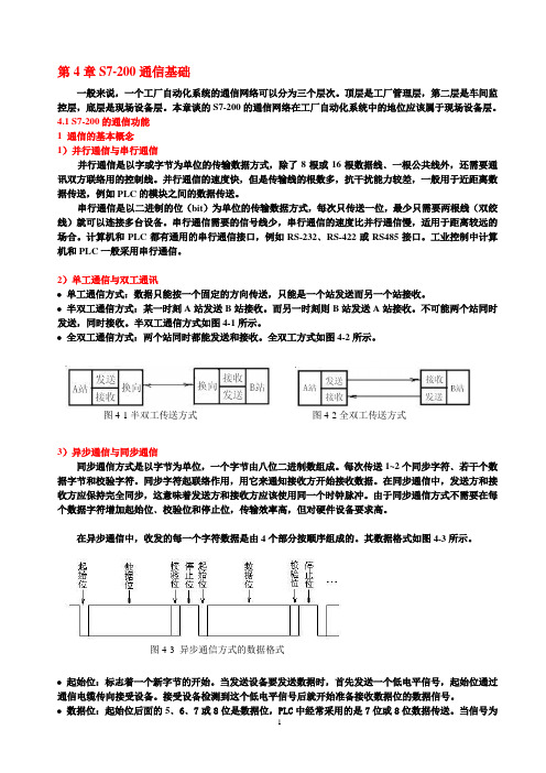
图4-1半双工传送方式图4-2全双工传送方式3)异步通信与同步通信同步通信方式是以字节为单位,一个字节由八位二进制数组成。
每次传送1~2个同步字符﹑若干个数据字节和校验字符。
同步字符起联络作用,用它来通知接收方开始接收数据。
在同步通信中,发送方和接收方应保持完全同步,这意味着发送方和接收方应该使用同一个时钟脉冲。
由于同步通信方式不需要在每个数据字符增加起始位﹑校验位和停止位,传输效率高,但对硬件设备要求高。
在异步通信中,收发的每一个字符数据是由4个部分按顺序组成的。
其数据格式如图4-3所示。
第8章 S7-200网络通信
Harbin Institute of Technology PAGE - 5 -
能单方向传递 全双工通信方式 数据可以在同一时刻双向传递
©
8.2 工业通信网络基础知识
3. 数据传输方式
指数据代码的传输顺序和数据传输时的同步方式。 并行传输和串行传输
串行传输时,数据的各个不同位分时使用同一条传输线,从低位开始一位接一位按顺序传送,数据有
跳变低电平表示逻辑“0” 缺点:信号速率是数据速率的2倍,需要双倍的传输 带宽
优点:具有内在时钟,不需要同步信号;双极性信号
中无直流分量
©
8.2 工业通信网络基础知识
2. 数据通信方式
在通信线路上,按照传输的方向分: 单工、半双工和全双工通信方式
单工通信方式 数据只能向一个方向传递
半双工通信方式
串行通信使用的两种同步方式 异步传输以字符为单位,使用字符同步
方式。实现简单,但传输效率低
同步传输以数据块(帧)为单位。传输 效率高,但发送端和接收端的时钟同步。 曼彻斯 特编码中可以提取同步信号,实现自同步
©
8.2 工业通信网络基础知识
4. 差错(误码)控制 --- 数据校验
奇偶校验
只介绍PPI通信。
点到点接口,即PPI接口(Point to Point Interface)
是西门子专门为 S7-200 系列PLC开发的通信协议,是令牌传递协议 是一个主/从协议,S7-200一般作为从站。在用户程序通过SMB30可以将S7-200 PLC 设置为主站模式,此CPU在RUN模式可以作为主站,可以读/写其它S7-200PLC的数据
现场总线 Profibus 多点链路MP I S7-200 智能模块 S7-200 S7-200 执行器级总线AS-i 传感器及执行部件 1 2 3 4 5 n S7-200
PLC毕业设计外文翻译--基于模块化 S7-200 培训设备的 PLC 开放实验设计
S7-200 based modular training facilities opento experimental designPLCPLC (programmable logic controller) is a micro-controller core, the computer technology, automatic control technology; communication network together network technology is an advanced automatic control device. The current PLC has become the three major branch of modern industrial automation Column (PLC, robotics, CAD / CAM), widely used in various fields of automation and control systems, various types of enterprises Industry require a certain amount of practical experience with such talent. Thus, PLC application technology has become the industrial automation technology relevant professional technical personnel and university students to learn important lessons.Siemens SIMATIC S7-200 series are small PLC, its high price in the domestic market large market share, because of its flexible and powerful communication features and other special advanced features are increasingly the more widely used in automatic control systems [1]. Siemens Automation and Drives Group is currently actively cooperate with colleges and universities Siemens to build the establishment of training center for small-scale automation, Qingdao University is one of them. Siemens to provide similar training center S7-200 training-related equipment and software development. Teachers take advantage of this favorable experimental conditions, based on the design of these devices to open .Made a number of pilot projects PLC open, so that school has spare capacity, "enough" to further strengthen the PLC application technology student learning, Understand and operate the most advanced automation equipment, the initial grasp of advanced control technologies of industrial automation and control system design technology patients, improve their practical ability to achieve training objectives applicable talents to meet community needs for such technical personnel requirements.1 Modular S7-200 training equipmentPrinciple and Application of PLC technology tolearn and master the necessary hardware and softwaretest platform to support. Siemens automatic in myschool Group set up jointly with the driver of a smallautomated training centers, equipped with 10 sets oftraining equipment S7-200, diagram at right .Figure(painted on some of the expansion module) below. Thedevice is modular in design, the main module in additionto superior performance, cost-effective .Higher CPU224XP host, but also comes with text display TD400C,with special PT100 temperature transmitter, Heaters, fans,and other physical control object, basic literacy trainingto achieve most of experiments, people could beconducted. Siemens products for the rich functionmodule, consider the cost and other factors, with acertain number of functional modules, including EM231RTD temperature measurement module, EM253 positioncontrol module, EM241 Modem communication module, CP243-1 Ethernet communication module, EM277 Prefabs-DP module, SP series weighing Siwarex MS weighing module sensors and extension of six modules, connected by bus expansion unit to achieve the function of switch-free wiring, training, experiments can be used interchangeably. Also comes with HMI (Human Machine Interface) devices TP177B, OP177B, MP277, etc. A total of 10 touch-screens, hanging in the equipment rack can also be supported by a separate operation. Using the standard package of equipment S7-300 rail card installed, so that reliable and stable module is installed, and when necessary S7-300 modules can be very easy to experiment with the addition of any module S7-300, the S7-200 and S7-300 the installation of a common platform. This experimental equipment for teaching, training and scientific research has provided teachers, good hardware conditions.2 PLC open to experimental designPLC courses each semester due to class a lot, by the laboratory equipment, space and curriculum hours restrictions, generally Principle and Application of PLC programs created in the experiment mainly supporting the basic instruction to practice, sequential control, a simple digital V olume control system design, such as the marquee design, automatic round trip transportation movement control, intersection traffic lights model control, Three-tier model of control of the elevator, the part of the experiment content is based, compulsory. For the S7-200 special high-level utility function Energy-rich extension module and field communication function widely used implementation is rarely involved. Taking into account students Ability to accept differences and experimental conditions, this part of the experiment for the content best suited to open experiment [2] , That is, relative to teachers Laboratory equipment and related information, made experimental mission requirements, prepared by the students to self test program to determine the effective efficiency measurement experiment Ifthe method of thinking so that students have more room to stimulate the students enthusiasm and initiative, ability of students to engineering practice, Ability to innovate, analyze and solve problems Ability of great importance [3] . Therefore, the use of existing experimental design Equipment, and taking into account the students learn to master the knowledge structure, design and development of some pilot projects open.2.1 The main module design based on the opening experimentUse of the main module, in addition to the completion of some basic PLC programming experiment, we can also perform some special functions [4] Experiment, Also practiced Micro / Win programming environment integrated with a variety of programming guide, are:(1) The main module includes TD400C, it is a highly cost-effective dedicated S7-200 PLC's new generation of text Display, is a simple man-machine interface device, no special configuration of HMI software, the use of Micro / WIN V4.0 SP4 to On the version of Chinese language interface in the configuration wizard to TD [5] . The configuration opening in TD400C experiments, show the user through the configuration Menu, the alarm menu, and interact with S7-200 CPU, CPU storage area for data access and editing, enabling small Type of human-computer interaction function with the control system, such as basic experiments with automatic round trip transportation control program can be realized Through the control panel to control the car motion state, and in position to reach both ends of the alarm screen limit, while TD400C modify the car to stay at the ends of time, so that the experimental effect is more rich and vivid, but also to enable students to understand the master Production site using the actual control equipment.(2) High-speed counter, high-speed output, internal and external interrupts and other useful special features, through an open experiment Learn and master, such as the first high-speed output by PTO (pulse train) output, and achieve the high-speed counter High-speed output of the PTO HSC0 count, the interrupt function by repeated HSC0 count, a programming Adjust the PWM (pulse width modulation) high-speed output, the timer interrupt to implement a second counter, and the current count value, PWM output duty cycle and other related content displayed on the TD 400C.(3) The main module with the PT100 temperature transmitter will be converted from 0 to 100 degrees C 0 ~ 10V analog input received as Into the CPU, the heater, fan and other physical control objects connected to the digital output on the CPU can be realized on analog Data transformation, manual PID control programming, using the configuration wizard to complete the PID, PID parameter self-tuning function of the experiment, so that Students deeply understand and master the industrial field of analog PID control knowledge and implementation.(4)Two S7-200 series PLC via RS232 communication cable, you can use the PPI protocol to form a Single master station communication network, can be PPI point to point communication experiment, to achieve data exchange between the two PLC, such as the I0.0 ~ I0.7 master map to the slave state of the Q0.0 ~ Q0.7, from the station I0.0 ~ I0.7 of the state map to the main station Q0.0 ~ Q0.7, the network will allow students to experience the simple wizard to use reading and writing instruction, and extended through the formation of PPI networks can be implemented Control functions are more complex.(5) S7-200 CPU's communications port supports a free-port communication mode; you can use user-defined communication protocol implementation now with the computer or other device with a serial communication interface for communication. Here, simple and easy for students to use Visual Basic (VB) language PC program to realize S7-200 CPU PC with the free port communication mode between the experimental [6], Completed by the PLC field switching, analog control of processing, the host computer realization of the process parameters of the monitoring, analysis, Statistics and revision, to provide a good interface for easy monitoring.2.2 CP243-1 Ethernet module based on the open design of experimentsSiemens SIMATIC NET Industrial Ethernet is an open communication system on top, can manage and control network Integration, and even can be integrated into the Internet, for remote control and provides the conditions for global networking. S7-200 PLC with a CP243-1 Ethernet module or Internet CP243-1 IT module S7-200 can be connected to the Ethernet. In this, select are CP243-1 expansion module some experiments, through the Micro / WIN configuration of the Ethernet Wizard to complete the simple model Block configuration. Computer by installing the Ethernet card and Micro / WIN, can be realized via Ethernet S7-200 CPU Remote programming, configuration and diagnostics. In addition, the two are equipped with CP243-1 module S7-200 PLC, through the software programming and download the configuration program, can be realized through the network cable to connect two S7-200 PLC Ethernet-based data exchange. By This experiment allows students to commonly used industrial site between the S7-200 Ethernet communications have a clear understanding.2.3 touch screen design based on the opening experimentTD400C can only display text information, and requirements of many industrial control systems controlled object has a strong human-machine interface function can, through the meaning and message with a clear picture to the operator and control systems to achieve dialogue and interaction between Uses. Man-machine interface touch screen is the direction of development. Touch-screen devices using existing open experiment designed to allow students to learn as He through the configuration software WinCC Flexible configuration of the touch screen and transfer procedures [7] And the HMI and PLC data Exchange and data structures, such as students in the HMI configuration of traffic light system is running on a monitor screen or inside the elevator car operation For interface, combined with the preparation of the experiment based on the S7-200 signal-controlled crossroads of three elevator control procedures or procedures, Testing procedures can be performed correctly, but also to enable students to operate advanced equipment, and learn its configuration methods. In addition, to learn Students design a running effect of the controlled object interface, such as the movement of car transport materials, machinery and hand movement, etc., can make up for lab Less than the actual controlled object in the defect, this can greatly help students in the ability to innovate, improve and control system features a rich, Stimulate enthusiasm for learning and enthusiasm.Given above, S7-200 using the modular design of the part of the training facilitiesopens to experimental projects. Specialized courses as students learn The deepening of learning, knowledge, and plenty of time to increase reserves under the circumstances, but also in the graduation project will combine multiple modules Together to achieve a relatively complex system, such as the S7-300 CPU access system, with the S7-200 to achieve the Prefabs, MPI communications, the use of EM253 motion control position control module, servo motor and stepper motor control knowledge and understanding And control and so on.3 ConclusionsFull use of existing modular laboratory S7-200 training equipment, a large number of open research and development pilot project to enrich the real Test content, broaden the horizons of students, for students to learn deeply felt PLC interesting, learning PLC useful, while students mastered Industrial field is currently producing more with the typical products and the latest Siemens technology development and application of a comprehensive understanding of PLC control Technology, computer industry configuration control, touch screen control, networking, and automation control systems in real mutual penetration And added that practical ability of students to analyze and solve problems in the comprehensive capabilities have been greatly improved, more confident To face the fierce competition for jobs, it was widely welcomed by students.外文资料翻译基于模块化 S7-200 培训设备的 PLC 开放实验设计PLC(可编程序控制器)是以微控制器为核心,把计算机技术、自动控制技术、通信网络技术融合在一起的一种先进的自动控制装置。
英文翻译
西安科技大学毕业设计(论文)英文文献翻译题目西门子S7—200院、系(部) 机械工程学院专业及班级机械电子工程1002姓名赵奕杰指导教师李建华日期 2013年06月08号Features of the S7-200The S7-200 provides several special features that allow you to customize how the S7-200 functions to better fit your application.The S7-200 Allows Your Program to Immediately Read or Write the I/OThe S7-200 instruction set provides instructions that immediately read from or write to the physical I/O. These immediate I/O instructions allow direct access to the actual input or output point, even though the image registers are normally used as either the source or the destination for I/O accesses.The corresponding process-image input register location is not modified when you use an immediate instruction to access an input point. The corresponding process-image output register location is updated simultaneously when you use an immediate instruction to access an output point.TipThe S7-200 handles reads of analog inputs as immediate data, unless you enable analog input filtering. When you write a value to an analog output, the output is updated immediately.It is usually advantageous to use the process-image register rather than to directly access inputs or outputs during the execution of your program. There are three reasons for using the image registers:- The sampling of all inputs at the start of the scan synchronizes and freezes the values of the inputs for the program execution phase of the scan cycle. The outputs are updated from the image register after the execution of the program is complete. This provides a stabilizing effect on the system.- Your program can access the image register much more quickly than it can access I/O points, allowing faster execution of the program.- I/O points are bit entities and must be accessed as bits or bytes, but you can access the image register as bits, bytes, words, or double words. Thus, the image registers provideadditional flexibility.The S7-200 Allows Your Program to Interrupt the Scan CycleIf you use interrupts, the routines associated with each interrupt event are stored as part of the program. The interrupt routines are not executed as part of the normal scan cycle, but are executed when the interrupt event occurs (which could be at any point in the scan cycle).Interrupts are serviced by the S7-200 on a first-come-first-served basis within their respective priority assignments.The S7-200 Allows You to Allocate Processing Time for Run Mode Edit and Execution StatusYou can configure a percentage of the scan cycle to be dedicated for processing a run mode edit compilation or execution status. (Run mode edit and execution status are options provided by STEP 7--Micro/WIN to make debugging your program easier.) As you increase the percentage of time that is dedicated to these two tasks, you increase the scan time, which makes your control process run more slowly.The default percentage of the scan dedicated to processing run mode edits and execution status is set to 10%. This setting was chosen to provide a reasonable compromise for processing the compilation and status operations while minimizing the impact to your control process. You can adjust this value by 5% increments up to a maximum of 50%. To set the scan cycle time-slice for background communications:1. Select the View > Component > System Block menu command and select Background Time.2. In the Background tab, use the drop down box to select the communications background time.3. Click OK to save your selection.4. Download the modified system block to the S7-200.Figure 1 Communications Background TimeThe S7-200 Allows You to Set the States of Digital Outputs for Stop Mode The output table of the S7-200 allows you to determine whether to set the state of the digital output points to known values upon a transition to the STOP mode, or to leave the outputs in the state they were in before the transition to the STOP mode. The output table is part of the system block that is downloaded and stored in the S7-200.1. Select the View > Component > System Block menu command and select Output Table. Click on the Digital tab.2. To freeze the outputs in their last state, select the Freeze Outputs checkbox.3. To copy the table values to the outputs, enter the output table values by clicking the checkbox for each output bit you want to set to On (1) after a run-to-stop transition. The default values of the table are all zeroes.4. Click OK to save your selections.5. Download the modified system block to the S7-200.Figure 2 Digital Output TableThe S7-200 Allows You to Configure the Value of Analog OutputsThe Analog Output Table allows you to set analog output points to known values after a RUN-to-STOP transition, or to preserve the output values that existed before the transition to STOP mode. The Analog Output table is part of the system block that is downloaded and stored in the S7-200 CPU.1. Select the View > Component > System Block menu command and select Output Table. Click on the Analog tab.2. To freeze the outputs in their last state, select the Freeze Outputs check box.3. The Freeze Values table allows you to set the analog outputs to a known value (--32768 to 37262), on a RUN-to-STOP transition.4. Click OK to save your selections.5. Download the modified system block to the S7-200.Figure 3 Analog Output TableThe S7-200 Allows You to Define Memory to Be Retained on Loss of Power You can define up to six retentive ranges to select the areas of memory you want to retain through power cycles. You can define ranges of addresses in the following memory areas to be retentive: V, M, C, and T. For timers, only the retentive timers (TONR) can be retained. The default setting for the first 14 bytes of M Memory is to be non-retentive.Only the current values for timers and counters can be retained: the timer and counter bits are not retentive.TipChanging the range MB0 to MB13 to be retentive enables a special feature that automatically saves these locations to the permanent memory on power down.To define the retentive memory:1. Select the View > Component > System Block menu command and select Retentive Ranges.2. Select the ranges of memory to be retained following loss of power and click OK.3. Download the modified system block to the S7-200.Figure 4 Retentive MemoryThe S7-200 Allows You to Filter the Digital InputsThe S7-200 allows you to select an input filter that defines a delay time (selectable from 0.2 ms to 12.8 ms) for some or all of the local digital input points. This delay helps to filter noise on the input wiring that could cause inadvertent changes to the states of the inputs.The input filter is part of the system block that is downloaded and stored in the S7-200. The default filter time is 6.4 ms. As shown in Figure 4, each delay specification applies to groups of input points.To configure the delay times for the input filter:1. Select the View > Component > System Block menu command and select Input Filters. Click on the Digital tab.2. Enter the amount of delay for each group of inputs and click OK.3 Download the modified system 3. Download the modified system block to the S7-200.TipThe digital input filter affects the input value as seen by instruction reads, input interrupts,and pulse catches. Depending on your filter selection, your program could miss an interrupt event or pulse catch. The high speed counters count the events on the unfiltered inputs.The S7-200 Allows You to Filter the Analog InputsThe S7-200 allows you to select software filtering on individual analog inputs. The filtered value is the average value of a preselected number of samples of the analog input. The filter specification (number of samples and deadband) is the same for all analog inputs for which filtering is enabled.The filter has a fast response feature to allow large changes to be quickly reflected in the filter value. The filter makes a step function change to the latest analog input value when the input exceeds a specified change from the current value. This change, called the deadband, is specified in counts of the digital value of the analog input.The default configuration is to enable filtering for all analog inputs except AIW0 and AIW2 on CPU 224XP.1. Select the View > Component > System Block menu command and select Input Filters. Click on the Analog tab.2. Select the analog inputs that you want to filter, the number of samples, and the deadband.3. Click OK.4. Download the modified system block to the S7-200.Figure 5 Analog Input FilterTipDo not use the analog filter with modules that pass digital information or alarm indications in the analog words. Always disable analog filtering for RTD, Thermocouple, and AS-Interface Master modules.TipAIW0 and AIW2 on the CPU 224XP are filtered by the analog to digital converter, and usually will not need the additional software filter.The S7-200 Allows You to Catch Pulses of Short DurationThe S7-200 provides a pulse catch feature which can be used for some or all of the local digital input points. The pulse catch feature allows you to capture high-going pulses or low-going pulses that are of such a short duration that they would not always be seen when the S7-200 reads the digital inputs at the beginning of the scan cycle. When pulse catch is enabled for an input, a change in state of the input is latched and held until the next input cycle update. This ensures that a pulse which lasts for a short period of time is caught and held until the S7-200 reads the inputs.You can individually enable the pulse catch operation for each of the local digital inputs.To access the pulse catch configuration screen:1. Select the View > Component > System Block menu command and select Pulse Catch Bits.2. Click the corresponding check box and click OK.3. Download the modified system block to the S7-200.Figure 6 Pulse CatchFigure 7 shows the basic operation of the S7-200 with and without pulse catch enabled.Figure 7 Operation of the S7-200 with the Pulse Catch Feature Enabled and Disabled Because the pulse catch function operates on the input after it passes through the input filter, you must adjust the input filter time so that the pulse is not removed by the filter. Figure 8 shows a block diagram of the digital input circuit.Figure 8 Digital Input CircuitFigure 9 shows the response of an enabled pulse catch function to various input conditions. If you have more than one pulse in a given scan, only the first pulse is read. If you have multiple pulses in a given scan, you should use the rising/falling edge interrupt events.Figure 9 Responses of the Pulse Catch Function to Various Input Conditions外文翻译译文S7--200的特性S7--200提供了几条特殊的性能帮助您更好地运用S7--200的功能,完成应用程序。
完整S7-200说明书第四章的翻译。
PLC的基本概念The basic function of the S7-200 is to monitor field inputs and, based on your control logic, turn on or off field output devices. This chapter explains the concepts used to execute your program, the various types of memory used, and how that memory is retained.In This ChapterUnderstanding How the S7-200 Executes Your Control Logic . . . . . .24 Accessing the Data of the S7-200 . . . . . . . . . . . . . . . . . . . . .. . . . . . . ..27 Understanding How the S7-200 Saves and Restores Data . . . . . . . . . . 36 Selecting the Operating Mode for the S7-200 CPU . . . . . . . . . . . . . . . 40 Using the S7-200 Explorer . . . . . . . . . . . . . . . . . . .. . . . . . . . . . . . . . .. 41 Features of the S7-200 . . . . . . . . . . . . . . . . . . . . . . . . . . . . . . . .. . . . . . 41Understanding How the S7-200 Executes Your Control LogicThe S7-200 continuously cycles through the control logic in your program, reading and writing data.The S7-200 Relates Your Program to the Physical Inputs and Outputs The basic operation of the S7-200 is very simple:The S7-200 reads the status of the inputs.The program that is stored in the S7-200 uses these inputs to evaluate the control logic. As the program runs, the S7-200 updates the data.The S7-200 writes the data to the outputsFigure 4-1 shows a simple diagram of how an electrical relay diagram relates to theS7-200. In this example, the state of the switch for starting the motor is combined with the states of other inputs.The calculations of these states then determine the state for the output that goes to the actuator which starts the motor.The S7-200 Executes Its Tasks in a Scan CycleThe S7-200 executes a series of tasks repetitively. This cyclical execution of tasks is called the scan cycle. As shown in Figure 4-2, the S7-200 performs most or all of the following tasks during a scan cycle:Reading the inputs:The S7-200 copies the state of the physical inputs to the process-image inputregister.Executing the control logic in the program:The S7-200 executes the instructions of the program and stores the values inthe various memory areas.Processing any communications requests:The S7-200 performs any tasks required for communications.Executing the CPU self-test diagnostics:The S7-200 ensures that the firmware, the program memory, and anyexpansion modules are working properly.Writing to the outputs:The values stored in the process-image output register are written to thephysical outputs.The execution of the user program is dependent upon whether the S7-200 is in STOP mode or in RUN mode. In RUN mode, your program is executed; in STOP mode, your program is not executed.Reading the InputsDigital inputs: Each scan cycle begins by reading the current value of the digital inputs and then writing these values to the process-image input register.Analog inputs: The S7-200 does not update analog inputs from expansion modules as part of the normal scan cycle unless filtering of analog inputs is enabled. An analog filter is provided to allow you to have a more stable signal. You can enable the analog filter for each analog input point.When analog input filtering is enabled for an analog input, the S7-200 updates that analog input once per scan cycle, performs the filtering function, and stores the filtered value internally. The filtered value is then supplied each time your program accesses the analog input.When analog filtering is not enabled, the S7-200 reads the value of the analog input from expansion modules each time your program accesses the analog input.Analog inputs AIW0 and AIW2 included on the CPU 224XP are updated every scan with the most recent result from the analog-to-digital converter. This converter is an averaging type (sigma-delta) and those values will usually not need software filtering. TipAnalog input filtering is provided to allow you to have a more stable analog value. Use the analog input filter for applications where the input signal varies slowly with time. If the signal is a high-speed signal, then you should not enable the analog filter. Do not use the analog filter with modules that pass digital information or alarm indications in the analog words. Always disable analog filtering for RTD, Thermocouple, and AS-Interface Master modules.Executing the ProgramDuring the execution phase of the scan cycle, the S7-200 executes your program, starting with the first instruction and proceeding to the end instruction. The immediate I/O instructions give you immediate access to inputs and outputs during the execution of either the program or an interrupt routine.If you use subroutines in your program, the subroutines are stored as part of the program. The subroutines are executed when they are called by the main program, by another subroutine, or by an interrupt routine. Subroutine nesting depth is 8 from the main and 1 from an interrupt routine.If you use interrupts in your program, the interrupt routines that are associated with the interrupt events are stored as part of the program. The interrupt routines are not executed as part of the normal scan cycle, but are executed when the interrupt event occurs (which could be at any point in the scan cycle).Local memory is reserved for each of eleven entities: one main, eight subroutine nesting levels when initiated from the main, one interrupt, and one subroutine nesting level when initiated from an interrupt routine. Local memory has a local scope in that it is available only within its associated program entity, and cannot be accessed by the other program entities. For more information about Local memory, refer to Local Memory Area: L in this chapter.Figure 4-3 depicts the flow of a typical scan including the Local memory usage and two interrupt events, one during the program--execution phase and another during the communications phase of the scan cycle. Subroutines are called by the next higher level, and are executed when called. Interrupt routines are not called; they are a result of an occurrence of the associated interrupt event.Processing Any Communications RequestsDuring the message-processing phase of the scan cycle, the S7-200 processes any messages that were received from the communications port or intelligent I/O modules. Executing the CPU Self-test DiagnosticsDuring this phase of the scan cycle, the S7-200 checks for proper operation of the CPU and for the status of any expansion modules.Writing to the Digital OutputsAt the end of every scan cycle, the S7-200 writes the values stored in theprocess-image output register to the digital outputs. (Analog outputs are updated immediately, independently from the scan cycle.)Accessing the Data of the S7-200The S7-200 stores information in different memory locations that have unique addresses. You can explicitly identify the memory address that you want to access. This allows your program to have direct access to the information. Table 4-1 shows the range of integer values that can be represented by the different sizes of data.Table 4-1 Decimal and Hexadecimal Ranges f or the Different Sizes of DataTo access a bit in a memory area, you specify the address, which includes the memory area identifier, the byte address, and the bit number. Figure 4-4 shows an example of accessing a bit (which is also called “byte.bit” addressing). In this example, the memory area and byte address (I = input, and 3 = byte 3) are followed by a period (“.”) to separate the bit address (bit 4).You can access data in most memory areas (V, I, Q, M, S, L, and SM) as bytes, words, or double words by using the byte-address format. To access a byte, word, or double word of data in the memory, you must specify the address in a way similar to specifying the address for a bit. This includes an area identifier, data size designation, and the starting byte address of the byte, word, or double-word value, as shown in Figure 4-5.Data in other memory areas (such as T, C, HC, and the accumulators) are accessed by using an address format that includes an area identifier and a device number.Accessing Data in the Memory AreasProcess-Image Input Register: IThe S7-200 samples the physical input points at the beginning of each scan cycle and writes these values to the process-image input register. You can access theprocess-image input register in bits, bytes, words, or double words:Bit: I[byte address].[bit address] I0.1 Byte, Word, or Double Word: I[size][starting byte address] IB4Process-Image Output Register: QAt the end of the scan cycle, the S7-200 copies the values stored in the process-image output register to the physical output points. You can access the process-image output register in bits bytes, words, or double words:Bit: Q[byte address].[bit address] Q1.1 Byte, Word, or Double Word: Q[size][starting byte address] QB5Variable Memory Area: VYou can use V memory to store intermediate results of operations being performed by the control logic in your program. You can also use V memory to store other data pertaining to your process or task. You can access the V memory area in bits, bytes, words, or double words:Bit: V[byte address].[bit address] V10.2 Byte, Word, or Double Word: V[size][starting byte address] VW100Bit Memory Area: MYou can use the bit memory area (M memory) as control relays to store the intermediate status of an operation or other control information. You can access the bit memory area in bits, bytes, words, or double words:Bit: M[byte address].[bit address] M26.7 Byte, Word, or Double Word: M[size][starting byte address] MD20Timer Memory Area: TThe S7-200 provides timers that count increments of time in resolutions (time-base increments) of 1 ms, 10 ms, or 100 ms. Two variables are associated with a timer: Current value: this 16-bit signed integer stores the amount of time counted by the timer.Timer bit: this bit is set or cleared as a result of comparing the current and the preset value. The preset value is entered as part of the timer instruction.You access both of these variables by using the timer address (T + timer number). Access to either the timer bit or the current value is dependent on the instruction used:instructions with bit operands access the timer bit, while instructions with word operands access the current value. As shown in Figure 4-6, the Normally Open Contact instruction accesses the timer bit, while the Move Word instruction accesses the current value of the timer.Format: T[timer number] T24Counter Memory Area: CThe S7-200 provides three types of counters that count each low-to-high transition event on the counter input(s): one type counts up only, one type counts down only, and one type counts both up and down. Two variables are associated with a counter.Current value: this 16-bit signed integer stores the accumulated count.Counter bit: this bit is set or cleared as a result of comparing the current and the preset value. The preset value is entered as part of the counter instruction.You access both of these variables by using the counter address (C + counter number). Access to either the counter bit or the current value is dependent on the instruction used: instructions with bit operands access the counter bit, while instructions with word operands access the current value. As shown in Figure 4-7, the Normally Open Contact instruction accesses the counter bit, while the Move Word instruction accesses the current value of the counter.Format: C[counter number] C24High-Speed Counters: HCThe high-speed counters count high-speed events independent of the CPU scan. High-speed counters have a signed, 32-bit integer counting value (or current value). To access the count value for the high-speed counter, you specify the address of the high-speed counter, using the memory type (HC) and the counter number (such as HC0). The current value of the high-speed counter is a read-only value and can be addressed only as a double word (32 bits).Format: HC[high-speed counter number] HC1Accumulators: ACThe accumulators are read/write devices that can be used like memory. For example, you can use accumulators to pass parameters to and from subroutines and to store intermediate values used in a calculation. The S7-200 provides four 32-bit accumulators (AC0, AC1, AC2, and AC3). You can access the data in the accumulators as bytes, words, or double words.The size of the data being accessed is determined by the instruction that is used to access the accumulator. As shown in Figure 4-8, you use the least significant 8 or 16 bits of the value that is stored in the accumulator to access the accumulator as bytes or words. To access the accumulator as a double word, you use all 32 bits.For information about how to use the accumulators within interrupt subroutines, refer to the Interrupt Instructions in Chapter 6.Format: AC[accumulator number ] AC0Special Memory: SMThe SM bits provide a means for communicating information between the CPU and your program. You can use these bits to select and control some of the special functions of the S7-200 CPU, such as: a bit that turns on for the first scan cycle, a bit that toggles at a fixed rate, or a bit that shows the status of math or operational instructions. (For more information about the SM bits, see Appendix D.) You can access the SM bits as bits, bytes, words, or double words:Bit: SM[byte address].[bit address] SM0.1 Byte, Word, or Double Word: SM[size][starting byte address] SMB86 Local Memory Area: LThe S7-200 provides 64 bytes of local memory of which 60 can be used as scratchpad memory or for passing formal parameters to subroutines.TipIf you are programming in either LAD or FBD, STEP 7--Micro/WIN reserves the last four bytes of local memory for its own use.Local memory is similar to V memory with one major exception. V memory has a global scope while L memory has a local scope. The term global scope means that the same memory location can be accessed from any program entity (main program, subroutines, or interrupt routines). The term local scope means that the memory allocation is associated with a particular program entity. The S7-200 allocates 64 bytes of L memory for the main program, 64 bytes for each subroutine nesting level, and 64 bytes for interrupt routines.The allocation of L memory for the main program cannot be accessed from subroutines or from interrupt routines. A subroutine cannot access the L memory allocation of the main program, an interrupt routine, or another subroutine. Likewise, an interrupt routine cannot access the L memory allocation of the main program or of a subroutine.The allocation of L memory is made by the S7-200 on an as-needed basis. This means that while the main portion of the program is being executed, the L memory allocations for subroutines and interrupt routines do not exist. At the time that an interrupt occurs or a subroutine is called, local memory is allocated as required. The new allocation of L memory might reuse the same L memory locations of a different subroutine or interrupt routine.The L memory is not initialized by the S7-200 at the time of allocation and might contain any value. When you pass formal parameters in a subroutine call, the values of the parameters being passed are placed by the S7-200 in the appropriate L memory locations of the called subroutine. Lmemory locations, which do not receive a value as a result of the formal parameter passing step,will not be initialized and might contain any value at the time of allocation.Bit: L[byte address].[bit address] L0.0Byte, Word, or Double Word: L[size] [starting byte address] LB33 Analog Inputs: AIThe S7-200 converts an analog value (such as temperature or voltage) into aword-length (16-bit) digital value. You access these values by the area identifier (AI), size of the data (W), and the starting byte address. Since analog inputs are words and always start on even-number bytes (such as 0, 2, or 4), you access them witheven-number byte addresses (such as AIW0, AIW2, or AIW4). Analog input values are read-only values.Format: AIW[starting byte address] AIW4Analog Outputs: AQThe S7-200 converts a word-length (16-bit) digital value into a current or voltage, proportional to the digital value (such as for a current or voltage). You write these values by the area identifier (AQ), size of the data (W), and the starting byte address. Since analog outputs are words and always start on even-number bytes (such as 0, 2, or 4), you write them with even-number byte addresses (such as AQW0, AQW2, or AQW4). Analog output values are write-only values.Format: AQW[starting byte address] AQW4Sequence Control Relay (SCR) Memory Area: SSCRs or S bits are used to organize machine operations or steps into equivalent program segments. SCRs allow logical segmentation of the control program. You can access the S bits as bits, bytes, words, or double words.Bit: S[byte address].[bit address] S3.1 Byte, Word, or Double Word: S[size][starting byte address] SB4 Format for Real NumbersReal (or floating-point) numbers are represented as 32-bit, single-precision numbers, whose format is described in the ANSI/IEEE 754--1985 standard. See Figure 4-9. Real numbers are accessed in double-word lengths.Accuracy when Calculating Real NumbersCalculations that involve a long series of values including very large and very small numbers can produce inaccurate results. This can occur if the numbers differ by 10 to the power of x, where x > 6.For example: 100 000 000 + 1 = 100 000 000Format for StringsA string is a sequence of characters, with each character being stored as a byte. The first byte of the string defines the length of the string, which is the number of characters. Figure 4-10 shows the format for a string. A string can have a length of 0 to 254 characters, plus the length byte, so the maximum length for a string is 255 bytes. A string constant is limited to 126 bytes.Specifying a Constant Value for S7-200 InstructionsYou can use a constant value in many of the S7-200 instructions. Constants can be bytes, words, or double words. The S7-200 stores all constants as binary numbers, which can then be represented in decimal, hexadecimal, ASCII, or real number (floating point) formats. See Table 4-2.TipThe S7-200 CPU does not support “data typing” or data checking (such as specifying that the constant is stored as an integer, a signed integer, or a double integer). For example, an Add instruction can use the value in VW100 as a signed integer value, while an Exclusive Or instruction can use the same value in VW100 as an unsigned binary value.Addressing the Local and Expansion I/OThe local I/O provided by the CPU provides a fixed set of I/O addresses. You can add I/O points to the S7-200 CPU by connecting expansion I/O modules to the right side of the CPU, forming an I/O chain. The addresses of the points of the module are determined by the type of I/O and the position of the module in the chain, with respect to the preceding input or output module of the same type. For example, an output module does not affect the addresses of the points on an input module, and vice versa. Likewise, analog modules do not affect the addressing of digital modules, and vice versa.TipProcess-image register space for digital I/O is always reserved in increments of eight bits (one byte). If a module does not provide a physical point for each bit of each reserved byte, these unused bits cannot be assigned to subsequent modules in the I/O chain. For input modules, the unused bits are set to zero with each input update cycle.Analog I/O points are always allocated in increments of two points. If a module does not provide physical I/O for each of these points, these I/O points are lost and are notavailable for assignment to subsequent modules in the I/O chain.Figure 4-11 provides an example of the I/O numbering for a particular hardware configuration. The gaps in the addressing (shown as gray italic text) cannot be used by your program.Using Pointers for Indirect Addressing of the S7-200 Memory Areas Indirect addressing uses a pointer to access the data in memory. Pointers are double word memory locations that contain the address of another memory location. You can only use V memory locations, L memory locations, or accumulator registers (AC1, AC2, AC3) as pointers.To create a pointer, you must use the Move Double Word instruction to move the address of the indirectly addressed memory location to the pointer location. Pointers can also be passed to a subroutine as a parameter.The S7-200 allows pointers to access the following memory areas: I, Q, V, M, S, AI, AQ, SM, T (current value only), and C (current value only). You cannot use indirect addressing to access an individual bit or to access HC or L memory areas.To indirectly access the data in a memory address, you create a pointer to that location by entering an ampersand (&) and the memory location to be addressed. The input operand of the instruction must be preceded with an ampersand (&) to signify that theaddress of a memory location, instead of its contents, is to be moved into the location identified in the output operand of the instruction (the pointer).Entering an asterisk (*) in front of an operand for an instruction specifies that the operand is a pointer. As shown in Figure 4-12, entering *AC1 specifies that AC1 is a pointer to the word-length value being referenced by the Move Word (MOVW) instruction. In this example, the values stored in both VB200 and VB201 are moved to accumulator AC0.As shown in Figure 4-13, you can change the value of a pointer. Since pointers are 32-bit values, use double-word instructions to modify pointer values. Simple mathematical operations, such as adding or incrementing, can be used to modify pointer values.TipRemember to adjust for the size of the data that you are accessing: to access a byte, increment the pointer value by 1; to access a word or a current value for a timer or counter, add or increment the pointer value by 2; and to access a double word, add or increment the pointer value by 4.Understanding How the S7-200 Saves and Restores DataThe S7-200 provides a variety of features to ensure that your user program and data are properly retained in the S7-200.Retentive Data Memory -- Areas of data memory the user selects to remain unchanged over a power cycle, as long as the super capacitor and the optional battery cartridge have not been discharged. V, M, Timer Currents, and Counter Currents are the only data memory areas that are configurable to be retentivePermanent Memory -- Non-volatile memory used to store the program block, data block, system block, forced values, M memory configured to be saved on loss of power, and selected values written under user program controlMemory Cartridge -- Removable non-volatile memory used to store the program block, data block, system block, recipes, data logs, and forced valuesYou can use the S7-200 Explorer to store documentation files (doc, text, pdf, etc.) into the cartridge. You can also use the S7-200 Explorer to perform general file maintenance on the memory cartridge (copy, delete, directory and launch).To install a memory cartridge, remove the plastic slot cover from the S7-200 CPU and insert the memory cartridge in the slot. The memory cartridge is keyed for proper installation.CautionElectrostatic discharge can damage the memory cartridge or the receptacle on theS7-200 CPU. Make contact with a grounded conductive pad and/or wear a grounded wrist strap when you handle the cartridge. Store the cartridge in a conductive container.Downloading and Uploading the Elements of Your ProjectYour project consists of different elements:_ Program block_ Data block (optional)_ System block (optional)_ Recipes (optional)_ Data log configurations (optional)When you download a project, the program block, data block and system block are stored in permanent memory for safekeeping. Recipes and data log configurations are stored in the memory cartridge, and replace any existing recipes and data logs. Any program elements not included in the download operation are left unchanged in permanent memory and the memory cartridge.If a project download includes recipes or data log configurations, the memory cartridge must remain installed for proper program operation.To download your project to an S7-200 CPU:1.Select the File > Download menu command.2.Click each project element you wish to download.3.Click the Download Button.When you upload a project to your computer using STEP 7--Micro/WIN, the S7-200 uploads the program block, data block and system block from permanent memory. The recipes and data log configurations are uploaded from the memory cartridge. The data from the data logs is not uploaded to your computer using STEP7--Micro/WIN. The S7-200 Explorer is used to upload the data from the data logs (see Chapter 14). To upload your project from an S7-200 CPU:1.Select the File > Upload menu command.2.Click each project element that you wish to upload.3.Click the Upload Button.Storing your Program on a Memory CartridgeThe S7-200 allows you to copy your user program from one CPU to another using a memory cartridge. You can also distribute updates for any of the following blocks in your S7-200: the program block, system block or data block.Before copying any program elements to the memory cartridge, STEP 7--Micro/WIN deletes all program elements (including recipes and data logs) except for user files on the memory cartridge. If your program will not fit because of the size of your files, you can do one of two things to create enough storage space for your program. You can either erase the memory cartridge using the PLC > Erase Memory Cartridge menu command. Or, you can open the S7-200 Explorer and remove user files that are no longer needed.The PLC must be in STOP mode to program the memory cartridge.To store your program in the memory cartridge:1.Select the PLC > Program Memory Cartridge menu command.2.Click each project element you wish to copy to the memory cartridge (all programelementsthat exist in your project are selected by default). If the system block is selected the force values will be copied as well.3. Click the Program Button.The program block, system block, data block, and any forced values are copied from permanent memory in the S7-200 to the memory cartridge. The recipes and data log configurations are copied from STEP 7--Micro/WIN to the memory cartridge. Restoring a Program from a Memory CartridgeTo transfer the program from a memory cartridge to the S7-200, you must apply power to the S7-200 with the memory cartridge installed. If any of the blocks or force values present in the memory cartridge are different from the blocks or force values in the S7-200, then all blocks present in the memory cartridge are copied to the S7-200. If a program block was transferred from the memory cartridge, the program block in permanent memory is replaced.If a data block was transferred from the memory cartridge, the data block in permanent memory is replaced, all of V memory is cleared, and V memory isinitialized with the contents of the data block.If a system block was transferred from the memory cartridge, the system block and force values in the permanent memory are replaced and all retentive memory is cleared.Once the transferred program has been stored to permanent memory you can remove the memory cartridge. However, if recipes or data logs are present in the cartridge, you must leave the memory cartridge installed. Leaving the memory cartridge installed will delay entry to RUN mode on subsequent power cycles.NoticePowering on an S7-200 CPU with an installed memory cartridge that was programmed by a different model of S7-200 CPU can cause an error. Memory cartridges that are programmed by a lower model number CPU can be read by a higher model number CPU. However, the opposite is not true. For example, memory cartridges that are programmed by a CPU 221 orCPU 222 can be read by a CPU 224, but memory cartridges that are programmed by a CPU 224 are rejected by a CPU 221 or CPU 222.For a complete list of memory cartridge usage restrictions, see Optional Cartridges (Memory Cartridge) in Appendix A.Saving the Retentive M Memory Area on Power LossIf you configured any of the first 14 bytes of bit memory (MB0 to MB13) to be retentive, these bytes are saved to permanent memory when the S7-200 loses power. By default, the first 14 bytes of M memory are selected to be non-retentive. Restoring Data after Power OnWhen power is applied, the S7-200 restores the program block and the system block from permanent memory. The S7-200 then verifies that the super capacitor and optional battery cartridge, if installed, has successfully maintained the data stored in RAM memory. If the data was successfully maintained, the retentive areas of user data memory are left unchanged. The non-retentive portions of V memory are。
第8章 s7-200的通信与网络
第8章 s7-200的通信与网络本章要点●通信基本概念和术语● S7-200PLC通信部件的介绍● S7-200PLC通信协议与通信8.1 通信的基本知识在计算机控制与网络技术不断推广和普及的今天,对参与控制系统中的设备提出了可相互连接,构成网络及远程通信的要求,可编程控制器生产厂商为此加强了可编程控制器的网络通信能力。
8.1.1 基本概念和术语1. 并行传输与串行传输并行传输是指通信中同时传送构成一个字或字节的多位二进制数据。
而串行传输是指通信中构成一个字或字节的多位二进制数据是一位一位被传送的。
很容易看出两者的特点,与并行传输相比,串行传输的传输速度慢,但传输线的数量少,成本比并行传输低,故常用于远距离传输且速度要求不高的场合,如计算机与可编程控制器间的通信、计算机USB口与外围设备的数据传送。
并行传输的速度快,但传输线的数量多,成本比高,故常用于近距离传输的场合,如计算机内部的数据传输、计算机与打印机的数据传输。
2. 异步传输和同步传输在异步传输中,信息以字符为单位进行传输,当发送一个字符代码时,字符前面都具有自己的一位起始位,极性为0,接着发送5到8位的数据位、1位奇偶校验位,1到2位的停止位,数据位的长度视传输数据格式而定,奇偶校验位可有可无,停止位的极性为1,在数据线上不传送数据时全部为1。
异步传输中一个字符中的各个位是同步的,但字符与字符之间的间隔是不确定的,也就是说线路上一旦开始传送数据就必须按照起始位、数据位、奇偶校验位、停止位这样的格式连续传送,但传输下一个数据的时间不定,不发送数据时线路保持1状态。
异步传输的优点就是收、发双方不需要严格的位同步,所谓“异步”是指字符与字符之间的异步,字符内部仍为同步。
其次异步传输电路比较简单,链络协议易实现,所以得到了广泛的应用。
其缺点在于通信效率比较低。
在同步传输中,不仅字符内部为同步,字符与字符之间也要保持同步。
信息以数据块为单位进行传输,发送双方必须以同频率连续工作,并且保持一定的相位关系,这就需要通信系统中有专门使发送装置和接收装置同步的时钟脉冲。
S7-200的网络通信
S7-200的网络通信
温艳艳
【期刊名称】《天津职业院校联合学报》
【年(卷),期】2011(013)002
【摘要】S7-200系列PLC可方便地实现相互之间通信以及与其它智能设备进行通信.本文介绍了由S7-200 PLC组建的集中典型网络的通信协议和硬件连接设置.S7-200可支持多种通信协议,如点到点接口(PPI)、多点接口(MPI)和PROFIBUS-DP协议.这些协议的结构是基于7层开放系统互联参考模型(OSI),通过一个令牌环网来实现.
【总页数】3页(P75-77)
【作者】温艳艳
【作者单位】天津现代职业技术学院,天津市300222
【正文语种】中文
【中图分类】TP393
【相关文献】
1.如何用西门子S7-200芯片实现PLC的网络通信 [J], 王建章
2.S7-200 PLC的网络通信及应用 [J], 刘美俊
3.“S7-200 SMART PLC ”讲座第9讲:S7-200 SMART IE 触摸屏与S7-200 SMART通信的实现方法 [J], 廖常初
4.S7-200系列PLC与计算机网络通信的构建 [J], 麻桃花
5.S7-200系列PLC网络通信的应用 [J], 王成端
因版权原因,仅展示原文概要,查看原文内容请购买。
- 1、下载文档前请自行甄别文档内容的完整性,平台不提供额外的编辑、内容补充、找答案等附加服务。
- 2、"仅部分预览"的文档,不可在线预览部分如存在完整性等问题,可反馈申请退款(可完整预览的文档不适用该条件!)。
- 3、如文档侵犯您的权益,请联系客服反馈,我们会尽快为您处理(人工客服工作时间:9:00-18:30)。
毕业设计(论文)外文文献翻译文献、资料中文题目:理解S7--200网络通讯的基本概念文献、资料英文题目:文献、资料来源:文献、资料发表(出版)日期:院(部):专业:班级:姓名:学号:指导教师:翻译日期: 2017.02.14Understanding the Basics of S7-200 Network Communications Selecting the Communication Interface for Your NetworkThe S7-200 is designed to solve your communications and networking needs by supporting not only the simplest of networks but also supporting more complex networks. The S7-200 also provides tools that allow you to communicate with other devices, such as printers and weigh scales which use their owncommunications protocols.The S7-200 supports many different types of communication networks. The selection of a network isperformed within the Set PG/PC Interface property dialog. A selected network is referred to as an Interface. The different types of interfaces available to access these communication networks are:1. PPI Multi-Master cables2. CP communication cards3. Ethernet communication cardsTo select the communication interface for STEP 7--Micro/WIN, you perform the following steps. See Figure 7-1.1. Double-click the icon in the Communications Setup window.2. Select the interface parameter foFigure 7-1 STEP 7--Micro/WINCommunications InterfacePPI Multi-Master CablesThe S7-200 supports communication through two different types of PPI Multi-Master cables. These cable types permit communication through either an RS-232 or a USB interface.As shown in Figure 7-2, selecting the PPI Multi-Master cable type is simple. You perform the following steps:1. Click the Properties button on the Set PG/PC Interface property page.2. Click the Local Connection tab on the Properties page.3. Select the USB or the desired COM portFigure 7-2 PPI Multi-Master Cable SelectionTipPlease note that only one USB cable can be used at a time. TipExamples in this manual use the RS-232/PPI Multi-Master cable. The RS-232/PPI Multi-Master cable replaces the previous PC/PPI cable. A USB/PPI Multi-Master cable is also available. Refer to Appendix E for order numbers.Using Master and Slave Devices on a PROFIBUS NetworkThe S7-200 supports a master-slave network and can function as either a masteror a slave in a PROFIBUS network, while STEP 7--Micro/WIN is always a master.MastersA device that is a master on a network can initiate a request to another device on the network. A master can also respond to requests from other masters on the network. Typical master devices include STEP 7--Micro/WIN, human-machine interface devices such as a TD 200, and S7-300 or S7-400 PLCs. The S7-200 functions as a master when it is requesting information from another S7-200 (peer-to-peer communications).TipA TP070 will not work on a network with another master device.SlavesA device that is configured as a slave can only respond to requests from a master device; a slave never initiates a request. For most networks, the S7-200 functions as a slave. As a slave device, the S7-200 responds to requests from a network master device, such as an operator panel or STEP 7--Micro/WIN.Setting the Baud Rate and Network AddressThe speed that data is transmitted across the network is the baud rate, which is typically measured in units of kilobaud (kbaud) or megabaud (Mbaud). The baud rate measures how much data can be transmitted within a given amount of time. For example, a baud rate of 19.2 kbaud describes a transmission rate of 19,200 bits per second.Every device that communicates over a given network must be configured to transmit data at the same baud rate. Therefore, the fastest baud rate for the network is determined by the slowest device connected to the network.Table 7-1 lists the baud rates supported by the S7-200.Table 7-1 Baud Rates Supported by the S7-200The network address is a unique number that you assign to each device on the network. The unique network address ensures that the data is transferred to or retrieved from the correct device. The S7-200 supports network addresses from 0 to 126. For an S7-200 with two ports, each port has a network address. Table 7-2 lists the default (factory) settings for the S7-200 devices.Table 7-2 Default Addresses for S7-200 DevicesSetting the Baud Rate and Network Address for STEP 7--Micro/WINYou must configure the baud rate and network address for STEP 7--Micro/WIN. The baud rate must be the same as the other devices on the network, and the network address must be unique.Typically, you do not change the network address (0) for STEP 7--Micro/WIN. If your network includes another programming package, you might need to change the network address for STEP 7--Micro/WIN.As shown in Figure 7-3, configuring the baud rate and network address for STEP 7--Micro/WIN is simple. After you click the Communications icon in the Navigation bar, you perform the following steps:\Figure 7-3 Configuring STEP 7--Micro/WINFigure 7-3 Configuring STEP 7--Micro/WIN1. Double-click the icon in the Communications Setup window.2. Click the Properties button on the Set PG/PC Interface dialog box.3. Select the network address for STEP 7--Micro/WIN.4. Select the baud rate for STEP 7--Micro/WIN.Setting the Baud Rate and Network Address for the S7-200You must also configure the baud rate and network address for the S7-200. The system block of the S7-200 stores the baud rate and network address. After you select the parameters for the S7-200, you must download the system block to the S7-200.The default baud rate for each S7-200 port is 9.6 kbaud, and the default network address is 2.As shown in Figure 7-4, use STEP 7--Micro/WIN to set the baud rate and network address for the S7-200. After you select the System Block icon in the Navigation bar or select the View > Component > System Block menu command, you perform the following steps:1. Select the network address for the S7-200.2. Select the baud rate for the S7-200.3. Download the system block to the S7-200.Figure 7-4 Configuring the S7-200 CPUTipSelection of all baud rate options is permitted. STEP 7--Micro/WIN validates this selection during the download of the System Block. Baud rate selections that would prevent STEP 7--Micro/WIN from communicating with the S7-200 are prevented from being downloaded.Setting the Remote AddressBefore you can download the updated settings to the S7-200, you must set both the communications (COM) port of STEP 7--Micro/WIN (local) and the address of the S7-200 (remote) to match the current setting of the remote S7-200. See Figure 7-5.After you download the updated settings, you may need to reconfigure the PG/PC Interface baud rate setting (if different from the setting used when downloading to the remote S7-200). Refer to Figure 7-3 to configure the baud rate.Figure 7-5 Configuring STEP 7--Micro/WINSearching for the S7-200 CPUs on a NetworkYou can search for and identify the S7-200 CPUs that are attached to your network. You can also search the network at a specific baud rate or at all baud rates when looking for S7-200s.Only PPI Multi-Master cables permit searching of all baud rates. This feature is not available if communicating through a CP card. The search starts at the baud rate that is currently selected.1. Open the Communications dialog box and double-click the Refresh icon to start the search.2. To search all baud rates, select the Search All Baud Rates check box. 2. Selecting the Communications Protocol for Your Network The following information is an overview of the protocols supported by the S7-200 CPUs.1. Point-to-Point Interface (PPI)2. Multi-Point Interface (MPI)3. PROFIBUSFigure 7-6 Searching for CPUs on a NetworkBased on the Open System Interconnection (OSI) seven-layer model of communications architecture, these protocols are implemented on a token ring network which conforms to the PROFIBUS standard as defined in the European Standard EN 50170. These protocols are asynchronous, character-based protocols with one start bit, eight data bits, even parity, and one stop bit. Communications frames depend upon special start and stop characters, source and destination station addresses, frame length, and a checksum for data integrity. The protocols can run on a network simultaneously without interfering with each other, as long as the baud rate is the same for each protocol.Ethernet is also available for the S7-200 CPU with expansion modules CP243--1 and CP243--1 IT.PPI ProtocolPPI is a master-slave protocol: the master devices send requests to the slave devices, and the slave devices respond. See Figure 7-7. Slave devices do not initiate messages, but wait until a master sends them a request or polls them for a response.Masters communicate to slaves by means of a shared connection which is managed by the PPI protocol. PPI does not limit the number of masters that can communicate with any one slave; however, you cannot install more than 32 masterson the network.Figure 7-7 PPI NetworkS7-200 CPUs can act as master devices while they are in RUN mode, if you enable PPI master mode in the user program. (See the description of SMB30 in Appendix D.) After enabling PPI master mode, you can use the Network Read or the Network Write instructions to read from or write to other S7-200s.While the S7-200 is acting as a PPI master, it still responds as a slave to requests from other masters.。