Hardware implementation of the
安全组件的功能和实现方式概述
安全组件的功能和实现方式概述In the realm of information technology, security components play a pivotal role in safeguarding systems and data from unauthorized access and malicious attacks. These components are designed to enforce security policies, detect and respond to threats, and ensure the integrity of sensitive information. The implementation of security components often involves a multifaceted approach, encompassing hardware, software, and network-level security measures.在信息技术领域,安全组件在保护系统和数据免受未经授权的访问和恶意攻击方面发挥着关键作用。
这些组件旨在执行安全策略,检测和应对威胁,并确保敏感信息的完整性。
安全组件的实现通常涉及多方面的方法,包括硬件、软件和网络级别的安全措施。
Hardware security components, such as secure chips andtamper-resistant modules, provide a physical layer of protection by storing cryptographic keys and executing critical security functions. These components are designed to withstand physical attacks and ensure the confidentiality and authenticity of stored data.硬件安全组件,如安全芯片和防篡改模块,通过存储加密密钥和执行关键安全功能,提供了一层物理保护。
汽车电子功能安全标准ISO26262解析(三)——硬件部分

汽车电子功能安全标准ISO26262解析(三)——硬件部分汽车电子功能安全标准ISO26262解析(三)——硬件部分原创pianpian_zct 最后发布于2017-12-29 13:09:34 阅读数13865 收藏展开1. The necessary activities and processes for the product development at the hardware level include:(1) the hardware implementation of the technical safety concept;(2) the analysis of potential hardware faults and their effects;(3) the coordination with software development.为了满足ISO26262,硬件方面需要做的工作包括:(1) 功能安全概念的硬件实现;(2) 潜在硬件失效及后果分析;(3) 与软件开发协同合作。
2. 硬件功能安全相关工作:硬件功能安全方面相关工作包括:(1) 5.5 initiation of product development at the hardware level: 启动硬件设计具体包括哪些工作包?目的是决定并计划硬件设计每个阶段的功能安全活动。
输入:完善后的项目计划、完善前的安全计划、完善后的集成测试计划输出:完善后的安全计划(2) 5.6 specification of hardware safety requirements: 定义硬件功能安全需求输入:安全计划、安全概念、系统设计说明书、硬件软件接口说明输出:硬件安全需求(包括测试和验证标准)、完善的硬件软件接口说明、硬件安全需求验证报告如何定义硬件功能安全需求,使用什么工具软件,模板如何?They are derived from the technical safety concept and system design specification.硬件功能安全需求来源于系统安全概念和系统设计文档。
中文翻译
QAM is a widely used multilevel modulation technique,with a variety of applications in data radio communication systems.Most existing implementations of QAM-based systems use high levels of modulation in order to meet the high data rate constraints of emerging applications.This work presents the architecture of a highly parallel QAM modulator,using MPSoC-based design flow and design methodology,which offers multirate modulation.The proposed MPSoC architecture is modular and provides dynamic reconfiguration of the QAM utilizing on-chip interconnection networks,offering high data rates(more than1 Gbps),even at low modulation levels(16-QAM).Furthermore,the proposed QAM implementation integrates a hardware-based resource allocation algorithm that can provide better throughput and fault tolerance,depending on the on-chip interconnection network congestion and run-time faults.Preliminary results from this work have been published in the Proceedings of the18th IEEE/IFIP International Conference on VLSI and System-on-Chip(VLSI-SoC2010).The current version of the work includes a detailed description of the proposed system architecture,extends the results significantly using more test cases,and investigates the impact of various design parameters.Furthermore,this work investigates the use of the hardware resource allocation algorithm as a graceful degradation mechanism,providing simulation results about the performance of the QAM in the presence of faulty components.Quadrature Amplitude Modulation(QAM)is a popular modulation scheme,widely used in various communication protocols such as Wi-Fi and Digital Video Broadcasting(DVB).The architecture of a digital QAM modulator/demodulator is typically constrained by several, often conflicting,requirements.Such requirements may include demanding throughput, high immunity to noise,flexibility for various communication standards,and low on-chip power.The majority of existing QAM implementations follow a sequential implementation approach and rely on high modulation levels in order to meet the emerging high data rate constraints.These techniques,however,are vulnerable to noise at a given transmission power,which reduces the reliable communication distance.The problem is addressed by increasing the number of modulators in a system,through emerging Software-Defined Radio (SDR)systems,which are mapped on MPSoCs in an effort to boost parallelism.These works, however,treat the QAM modulator as an individual system task,whereas it is a task that can further be optimized and designed with further parallelism in order to achieve high data rates,even at low modulation levels.Designing the QAM modulator in a parallel manner can be beneficial in many ways.Firstly, the resulting parallel streams(modulated)can be combined at the output,resulting in a system whose majority of logic runs at lower clock frequencies,while allowing for high throughput even at low modulation levels.This is particularly important as lower modulation levels are less susceptible to multipath distortion,provide power-efficiency and achieve low bit error rate(BER).Furthermore,a parallel modulation architecture can benefit multiple-input multiple-output(MIMO)communication systems,where information is sent and received over two or more antennas often shared among many ing multiple antennas at both transmitter and receiver offers significant capacity enhancement on many modern applications,including IEEE802.11n,3GPP LTE,and mobile WiMAX systems, providing increased throughput at the same channel bandwidth and transmit power.Inorder to achieve the benefit of MIMO systems,appropriate design aspects on the modulation and demodulation architectures have to be taken into consideration.It is obvious that transmitter architectures with multiple output ports,and the more complicated receiver architectures with multiple input ports,are mainly required.However,the demodulation architecture is beyond the scope of this work and is part of future work.This work presents an MPSoC implementation of the QAM modulator that can provide a modular and reconfigurable architecture to facilitate integration of the different processing units involved in QAM modulation.The work attempts to investigate how the performance of a sequential QAM modulator can be improved,by exploiting parallelism in two forms:first by developing a simple,pipelined version of the conventional QAM modulator,and second, by using design methodologies employed in present-day MPSoCs in order to map multiple QAM modulators on an underlying MPSoC interconnected via packet-based network-on-chip (NoC).Furthermore,this work presents a hardware-based resource allocation algorithm, enabling the system to further gain performance through dynamic load balancing.The resource allocation algorithm can also act as a graceful degradation mechanism,limiting the influence of run-time faults on the average system throughput.Additionally,the proposed MPSoC-based system can adopt variable data rates and protocols simultaneously,taking advantage of resource sharing mechanisms.The proposed system architecture was simulated using a high-level simulator and implemented/evaluated on an FPGA platform.Moreover, although this work currently targets QAM-based modulation scenarios,the methodology and reconfiguration mechanisms can target QAM-based demodulation scenarios as well. However,the design and implementation of an MPSoC-based demodulator was left as future work.While an MPSoC implementation of the QAM modulator is beneficial in terms of throughput, there are overheads associated with the on-chip network.As such,the MPSoC-based modulator was compared to a straightforward implementation featuring multiple QAM modulators,in an effort to identify the conditions that favor the MPSoC implementation. Comparison was carried out under variable incoming rates,system configurations and fault conditions,and simulation results showed on average double throughput rates during normal operation and~25%less throughput degradation at the presence of faulty components,at the cost of approximately35%more area,obtained from an FPGA implementation and synthesis results.The hardware overheads,which stem from the NoC and the resource allocation algorithm,are well within the typical values for NoC-based systems and are adequately balanced by the high throughput rates obtained.Most of the existing hardware implementations involving QAM modulation/demodulation follow a sequential approach and simply consider the QAM as an individual module.There has been limited design exploration,and most works allow limited reconfiguration,offering inadequate data rates when using low modulation levels.The latter has been addressed through emerging SDR implementations mapped on MPSoCs,that also treat the QAM modulation as an individual system task,integrated as part of the system,rather than focusing on optimizing the performance of the modulator.Works inuse a specific modulation type;they can,however,be extended to use higher modulation levels in order toincrease the resulting data rate.Higher modulation levels,though,involve more divisions of both amplitude and phase and can potentially introduce decoding errors at the receiver,as the symbols are very close together(for a given transmission power level)and one level of amplitude may be confused(due to the effect of noise)with a higher level,thus,distorting the received signal.In order to avoid this,it is necessary to allow for wide margins,and this can be done by increasing the available amplitude range through power amplification of the RF signal at the transmitter(to effectively spread the symbols out more);otherwise,data bits may be decoded incorrectly at the receiver,resulting in increased bit error rate(BER). However,increasing the amplitude range will operate the RF amplifiers well within their nonlinear(compression)region causing distortion.Alternative QAM implementations try to avoid the use of multipliers and sine/cosine memories,by using the CORDIC algorithm, however,still follow a sequential approach.Software-based solutions lie in designing SDR systems mapped on general purpose processors and/or digital signal processors(DSPs),and the QAM modulator is usually considered as a system task,to be scheduled on an available processing unit.Works inutilize the MPSoC design methodology to implement SDR systems,treating the modulator as an individual system task.Results in show that the problem with this approach is that several competing tasks running in parallel with QAM may hurt the performance of the modulation, making this approach inadequate for demanding wireless communications in terms of throughput and energy efficiency.Another particular issue,raised in,is the efficiency of the allocation algorithm.The allocation algorithm is implemented on a processor,which makes allocation slow.Moreover,the policies used to allocate tasks(random allocation and distance-based allocation)to processors may lead to on-chip contention and unbalanced loads at each processor,since the utilization of each processor is not taken into account.In,a hardware unit called CoreManager for run-time scheduling of tasks is used,which aims in speeding up the allocation algorithm.The conclusions stemming from motivate the use of exporting more tasks such as reconfiguration and resource allocation in hardware rather than using software running on dedicated CPUs,in an effort to reduce power consumption and improve the flexibility of the system.This work presents a reconfigurable QAM modulator using MPSoC design methodologies and an on-chip network,with an integrated hardware resource allocation mechanism for dynamic reconfiguration.The allocation algorithm takes into consideration not only the distance between partitioned blocks(hop count)but also the utilization of each block,in attempt to make the proposed MPSoC-based QAM modulator able to achieve robust performance under different incoming rates of data streams and different modulation levels. Moreover,the allocation algorithm inherently acts as a graceful degradation mechanism, limiting the influence of run-time faults on the average system throughput.we used MPSoC design methodologies to map the QAM modulator onto an MPSoC architecture,which uses an on-chip,packet-based NoC.This allows a modular, "plug-and-play"approach that permits the integration of heterogeneous processing elements, in an attempt to create a reconfigurable QAM modulator.By partitioning the QAM modulator into different stand-alone tasks mapped on Processing Elements(PEs),weown SURF.This would require a context-addressable memory search and would expand the hardware logic of each sender PE's NIRA.Since one of our objectives is scalability,we integrated the hop count inside each destination PE's packet.The source PE polls its host NI for incoming control packets,which are stored in an internal FIFO queue.During each interval T,when the source PE receives the first control packet,a second timer is activatedfor a specified number of clock cycles,W.When this timer expires,the polling is halted and a heuristic algorithm based on the received conditions is run,in order to decide the next destination PE.In the case where a control packet is not received from a source PE in the specified time interval W,this PE is not included in the algorithm.This is a key feature of the proposed MPSoC-based QAM modulator;at extremely loaded conditions,it attempts to maintain a stable data rate by finding alternative PEs which are less busy.QAM是一种广泛应用的多级调制技术,在数据无线电通信系统中应用广泛。
基于单片机的智能门锁设计英文文献

基于单片机的智能门锁设计英文文献Title: Design of an Intelligent Door Lock System Based on Microcontroller.Abstract:This paper presents the design and implementation of an intelligent door lock system based on a microcontroller.The system utilizes voice recognition technology to authenticate users and grant access to the locked area. The hardware components of the system include a microcontroller, a gating circuit, an extended memory, and a voiceinput/output circuit. The software components comprisevoice training, voice recognition, voice data processing, and a voice-activated control module. This paper discusses the design considerations, hardware selection, software development, and testing of the system. The resultsobtained from the testing indicate that the system is reliable, accurate, and user-friendly.Keywords: Microcontroller, Intelligent Door Lock, Voice Recognition, Hardware Design, Software Development.I. Introduction.With the increasing demand for security and convenience in modern homes and offices, intelligent door lock systems have become a popular choice. These systems combine the traditional locking mechanism with advanced technologies such as voice recognition, fingerprint scanning, or facial recognition to provide secure and convenient access control. This paper focuses on the design and implementation of an intelligent door lock system based on a microcontroller and voice recognition technology.II. System Design.The intelligent door lock system is designed to authenticate users based on their voices and grant accessto the locked area. The system consists of hardware and software components. The hardware components include a microcontroller, a gating circuit, an extended memory, anda voice input/output circuit. The software components comprise voice training, voice recognition, voice data processing, and a voice-activated control module.The microcontroller serves as the brain of the system, controlling and coordinating all other components. It receives voice input from the user, processes it through the voice recognition module, and compares it with the pre-stored voice templates stored in the extended memory. If the match is successful, the gating circuit is activated, unlocking the door.III. Hardware Selection.In this system, the microcontroller plays a crucial role. We have chosen the SPCE061A single-chip microcontroller due to its excellent performance, low cost, and ease of programming. The gating circuit is designed to control the locking mechanism of the door. The SPR4096 extended memory is used to store the voice templates and other important data. The voice input/output circuit is responsible for capturing the user's voice and generatingthe necessary audio output.IV. Software Development.The software development process involves writing code for the voice training module, voice recognition module, voice data processing module, and voice-activated control module. The voice training module allows users to record their voices and create voice templates. The voice recognition module compares the user's voice input with the pre-stored voice templates and determines whether the match is successful. The voice data processing module handles the preprocessing and feature extraction of the voice signal. The voice-activated control module controls the gating circuit and unlocks the door if the voice recognition is successful.V. Testing and Evaluation.To evaluate the performance of the intelligent door lock system, we conducted rigorous testing. The testing included testing the accuracy of voice recognition, theresponse time of the system, and the durability of the hardware components. The results obtained from the testing indicate that the system is reliable, accurate, and user-friendly.VI. Conclusion.This paper presents the design and implementation of an intelligent door lock system based on a microcontroller and voice recognition technology. The system provides a secure and convenient access control mechanism for modern homes and offices. The hardware components include a microcontroller, a gating circuit, an extended memory, and a voice input/output circuit. The software components comprise voice training, voice recognition, voice data processing, and a voice-activated control module. The testing conducted on the system demonstrates itsreliability, accuracy, and user-friendliness. Future work includes enhancing the system's performance, integrating additional security features, and exploring other biometric technologies for authentication.。
hardware造句

1、BDHHI's newest brand, K2, is a commercial hardware line of door hardware and exit devices.BDHHI的最新的商标K2,该品牌专业制造商用类的五金门锁和门禁装置。
2、Exert oneself optimizes the soft hardware environment that the project builds.着力优化项目建设的软硬件环境。
3、It is more expensive to upgrade hardware than its software counterpart.硬件升级的价格要远高于相应软件升级的价格。
4、Farther down the road is the fu Zhong hardware and furniture wholesaler.一路下去,还能看到福中五金店和家具批发商。
5、H.264 HD video is hardware decoded via the gpu. 通过GPU进行硬件解码的H . 264高清视频。
6、Some prosectors actually use pruning shears from a hardware store, which are much less expensive.实际使用的多从五金行购买,这种是比较昂贵的。
7、Design of the Hardware for Embedded Communication Controller Chip MPC 850MPC850嵌入式通信开发平台的硬件设计8、Host switching in case of hardware failure.在硬件故障时进行主机切换。
9、Old hardware companies want a slice of the software sashimi.传统的硬件公司也想从软件产业分一杯羹。
操作系统-精髓与设计原理 WILLIAM STALLINGS 课后答案

www.khd课a后答w案.网com
-2-
www.khd课后a答w案.网com
TABLE OF CONTENTS Chapter 1 Computer System Overview...............................................................4 Chapter 2 Operating System Overview...............................................................7 Chapter 3 Process Description and Control........................................................8 Chapter 5 Concurrency: Mutual Exclusion and Synchronization .................10 Chapter 6 Concurrency: Deadlock and Starvation ..........................................17 Chapter 7 Memory Management .......................................................................20 Chapter 8 Virtual Memory ..................................................................................22 Chapter 9 Uniprocessor Scheduling...................................................................28 Chapter 11 I/O Management and Disk Scheduling ........................................32 Chapter 12 File Management ..............................................................................34
设备管理系统设计与实现

设备管理系统设计与实现-英语论文IntroductionWith the increasing number of electronic devices in our daily lives, managing them has become a challenging task. For this reason, device management systems have emerged as an effective solution to help manage devices, including computer systems, smartphones, and other electronic devices. This paper presents a design and implementation of a device management system that can help manage devices effectively.BackgroundDevice management systems are software systems designed to help manage electronic devices. They are essential in managing large-scale electronic devices and ensuring their efficient operation. Tasks that the device management system can perform include device configuration, inventory management, monitoring, maintenance, and device updates.The design and implementation of a device management system are critical to ensure that it meets the needs of the organization. When designing the system, the critical factors that need to be considered include the organization's needs, the devices to be managed, and the network infrastructure. The implementation of the system involves the development of software, hardware installation, and network configuration.Design and ImplementationThe device management system that we propose is composed of three key components: a device management server, agents, and a user interface. These components have different functionalities that collectively ensure effective devicemanagement.The device management server is the core component ofthe entire system. It is responsible for device configuration, inventory management, and monitoring of devices. The serveris installed on a dedicated computer system that is connected to the devices to be managed. The server runs device management software that facilitates device configuration, inventory management, and monitoring. The software enablesthe server to detect new devices on the network, collectdevice information, and control device settings.The device management agents are installed on thedevices to be managed. The agents are responsible for communicating with the management server and executing management tasks. The agents are installed on each device on the network, and they enable the server to access device information and remotely manage the devices. The agentsenable remote access and management of devices, making it possible to execute tasks such as software updates, device configuration, and maintenance.The user interface is the component that the systemusers interact with. The user interface enables users to interact with the system, view device information, andexecute management tasks remotely. The user interface is aweb-based application that is accessible from any device onthe network. The user interface is designed to be user-friendly, making it easy for users to navigate and access device information.In the implementation of the device management system,the installation of hardware and software is done in stages. First, the device management server is installed andconfigured to run device management software. Once the serveris installed, agents are installed on each device on the network. The agents are configured to communicate with the server, and they enable device management tasks to be executed remotely. Finally, the user interface is designed and installed, and it is configured to enable users to access device information and execute management tasks remotely.ConclusionThe design and implementation of a device management system are critical in ensuring effective device management. The system we propose is composed of three key components: a device management server, agents, and a user interface. The server is responsible for device configuration, inventory management, and monitoring of devices. Agents enable remote access and management of devices, while the user interface allows users to interact with the system and execute management tasks remotely. The implementation of the system involves the installation of hardware and software in stages. With this system in place, device management becomes more comfortable, ensuring efficient operation of electronic devices.。
FPGA的英文文献及翻译
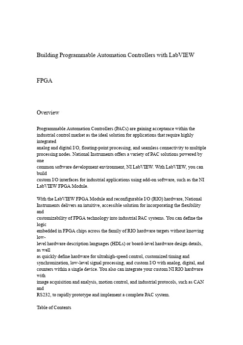
Building Programmable Automation Controllers with LabVIEW FPGAOverviewProgrammable Automation Controllers(PACs)are gaining acceptance within the industrial control market as the ideal solution for applications that require highly integratedanalog and digital I/O,floating-point processing,and seamless connectivity to multiple processing nodes.National Instruments offers a variety of PAC solutions powered by onecommon software development environment,NI LabVIEW.With LabVIEW,you can buildcustom I/O interfaces for industrial applications using add-on software,such as the NI LabVIEW FPGA Module.With the LabVIEW FPGA Module and reconfigurable I/O(RIO)hardware,National Instruments delivers an intuitive,accessible solution for incorporating the flexibility andcustomizability of FPGA technology into industrial PAC systems.You can define the logicembedded in FPGA chips across the family of RIO hardware targets without knowing low-level hardware description languages(HDLs)or board-level hardware design details, as wellas quickly define hardware for ultrahigh-speed control,customized timing and synchronization,low-level signal processing,and custom I/O with analog,digital,and counters within a single device.You also can integrate your custom NI RIO hardware withimage acquisition and analysis,motion control,and industrial protocols,such as CAN andRS232,to rapidly prototype and implement a complete PAC system.Table of Contents1.IntroductionNI RIO2.Hardware for PACsBuilding PACs with LabVIEW and bVIEW FPGA ModuleFPGA Development4.FlowUsing NI SoftMotion to Create5.Custom Motion ControllersApplications6.Conclusion7.IntroductionYou can use graphical programming in LabVIEW and the LabVIEW FPGA Module to configure the FPGA(field-programmable gate array)on NI RIO devices.RIO technology,themerging of LabVIEW graphical programming with FPGAs on NI RIO hardware, provides aflexible platform for creating sophisticated measurement and control systems that you couldhardware.custom-designed with only create previouslyAn FPGA is a chip that consists of many unconfigured logic gates.Unlike the fixed, vendor-defined functionality of an ASIC(application-specific integrated circuit)chip, you canconfigure and reconfigure the logic on FPGAs for your specific application.FPGAs are usedin applications where either the cost of developing and fabricating an ASIC is prohibitive,orthe hardware must be reconfigured after being placed into service.The flexible, software-programmable architecture of FPGAs offer benefits such as high-performance execution ofcustom algorithms,precise timing and synchronization,rapid decision making,and simultaneous execution of parallel tasks.Today,FPGAs appear in such devices as instruments,consumer electronics,automobiles,aircraft,copy machines,and application-specific computer hardware.While FPGAs are often used in industrial control products,FPGA functionality has not previously been made accessible to industrial control engineers. Defining FPGAs has historically required expertise using HDL programming or complexdesign tools used more by hardware design engineers than by control engineers.With the LabVIEW FPGA Module and NI RIO hardware,you now can use LabVIEW, ahigh-level graphical development environment designed specifically for measurement andcontrol applications,to create PACs that have the customization,flexibility,and high-performance of FPGAs.Because the LabVIEW FPGA Module configures custom circuitry inhardware,your system can process and generate synchronized analog and digital signalsrapidly and deterministically.Figure1illustrates many of the NI RIO devices that you canconfigure using the LabVIEW FPGA Module.bVIEW FPGA VI Block Diagram and RIO Hardware PlatformsNI RIO Hardware for PACsHistorically,programming FPGAs has been limited to engineers who have in-depth knowledge of VHDL or other low-level design tools,which require overcoming a very steeplearning curve.With the LabVIEW FPGA Module,NI has opened FPGA technology to abroader set of engineers who can now define FPGA logic using LabVIEW graphical development.Measurement and control engineers can focus primarily on their test and controlapplication,where their expertise lies,rather than the low-level semantics of transferring logicinto the cells of the chip.The LabVIEW FPGA Module model works because of the tightintegration between the LabVIEW FPGA Module and the commercial off-the-shelf (COTS)hardware architecture of the FPGA and surrounding I/O components.National Instruments PACs provide modular,off-the-shelf platforms for your industrialcontrol applications.With the implementation of RIO technology on PCI,PXI,and CompactVision System platforms and the introduction of RIO-based CompactRIO,engineers nowhave the benefits of a COTS platform with the high-performance,flexibility,and customization benefits of FPGAs at their disposal to build PACs.National Instruments PCIand PXI R Series plug-in devices provide analog and digital data acquisition and control forhigh-performance,user-configurable timing and synchronization,as well as onboard decisionmaking on a single ing these off-the-shelf devices,you can extend your NI PXI orPCI industrial control system to include high-speed discrete and analog control, customsensor interfaces,and precise timing and control.NI CompactRIO,a platform centered on RIO technology,provides a small,industrially rugged,modular PAC platform that gives you high-performance I/O and unprecedentedflexibility in system timing.You can use NI CompactRIO to build an embedded system forapplications such as in-vehicle data acquisition,mobile NVH testing,and embedded machinecontrol systems.The rugged NI CompactRIO system is industrially rated and certified, and itis designed for greater than50g of shock at a temperature range of-40to70°C.NI Compact Vision System is a rugged machine vision package that withstands the harshenvironments common in robotics,automated test,and industrial inspection systems. NICVS-145x devices offer unprecedented I/O capabilities and network connectivity for distributed machine vision applications.NI CVS-145x systems use IEEE1394 (FireWire)technology,compatible with more than40cameras with a wide range of functionality, performance,and price.NI CVS-1455and NI CVS-1456devices contain configurable FPGAs so you can implement custom counters,timing,or motor control in yourvision application.Building PACs with LabVIEW and the LabVIEW FPGA ModuleWith LabVIEW and the LabVIEW FPGA Module,you add significant flexibility and customization to your industrial control hardware.Because many PACs are already programmed using LabVIEW,programming FPGAs with LabVIEW is easy because it usesthe same LabVIEW development environment.When you target the FPGA on an NI RIOdevice,LabVIEW displays only the functions that can be implemented in the FPGA, furthereasing the use of LabVIEW to program FPGAs.The LabVIEW FPGA Module Functionspalette includes typical LabVIEW structures and functions,such as While Loops,For Loops,Case Structures,and Sequence Structures as well as a dedicated set of LabVIEW FPGA-specific functions for math,signal generation and analysis,linear and nonlinear control,comparison logic,array and cluster manipulation,occurrences,analog and digital I/O, andtiming.You can use a combination of these functions to define logic and embed intelligencedevice.RIO NI your ontoFigure2shows an FPGA application that implements a PID control algorithm on the NIRIO hardware and a host application on a Windows machine or an RT target that communicates with the NI RIO hardware.This application reads from analog input0 (AI0),performs the PID calculation,and outputs the resulting data on analog output0(AO0). Whilethe FPGA clock runs at40MHz the loop in this example runs much slower because eachcomponent takes longer than one-clock cycle to execute.Analog control loops can run on anFPGA at a rate of about200kHz.You can specify the clock rate at compile time.This example shows only one PID loop;however,creating additional functionality on the NI RIOdevice is merely a matter of adding another While Loop.Unlike traditional PCFPGAs are parallel processors.Adding additional loops to your application does not affect theperformance of your PID loop.Figure2.PID Control Using an Embedded LabVIEW FPGA VI with Corresponding LabVIEW Host VI.FPGA Development FlowAfter you create the LabVIEW FPGA VI,you compile the code to run on the NI RIO hardware.Depending on the complexity of your code and the specifications of your development system,compile time for an FPGA VI can range from minutes to several hours.To maximize development productivity,with the R Series RIO devices you can use a bit-accurate emulation mode so you can verify the logic of your design before initiating thecompile process.When you target the FPGA Device Emulator,LabVIEW accesses I/O fromthe device and executes the VI logic on the Windows development computer.In this mode,you can use the same debugging tools available in LabVIEW for Windows,such as executionhighlighting,probes,and breakpoints.Once the LabVIEW FPGA code is compiled,you create a LabVIEW host VI to integrateyour NI RIO hardware into the rest of your PAC system.Figure3illustrates the developmentprocess for creating an FPGA application.The host VI uses controls and indicators on theFPGA VI front panel to transfer data between the FPGA on the RIO device and the hostprocessing engine.These front panel objects are represented as data registers within theFPGA.The host computer can be either a PC or PXI controller running Windows or a PC,PXI controller,Compact Vision System,or CompactRIO controller running a real-time operating system(RTOS).In the above example,we exchange the set point,PID gains, looprate,AI0,and AO0data with the LabVIEW host VI.bVIEW FPGA Development FlowThe NI RIO device driver includes a set of functions to develop a communication interface to the FPGA.The first step in building a host VI is to open a reference to the FPGAVI and RIO device.The Open FPGA VI Reference function,as seen in Figure2,also downloads and runs the compiled FPGA code during execution.After opening the reference,you read and write to the control and indicator registers on the FPGA using theRead/WriteControl function.Once you wire the FPGA reference into this function,you can simply selectwhich controls and indicators you want to read and write to.You can enclose the FPGARead/Write function within a While Loop to continuously read and write to the FPGA. Finally,the last function within the LabVIEW host VI in Figure2is the Close FPGA VIReference function.The Close FPGA VI Reference function stops the FPGA VI and closesthe reference to the device.Now you can download other compiled FPGA VIs to the device tochange or modify its functionality.The LabVIEW host VI can also be used to perform floating-point calculations,data logging,networking,and any calculations that do not fit within the FPGA fabric.For addeddeterminism and reliability,you can run your host application on an RTOS with the LabVIEW Real-Time bVIEW Real-Time systems provide deterministic processing engines for functions performed synchronously or asynchronously to the FPGA.For example,floating-point arithmetic,including FFTs,PID calculations,and custom controlalgorithms,are often performed in the LabVIEW Real-Time environment.Relevant data canbe stored on a LabVIEW Real-Time system or transferred to a Windows host computeroff-line analysis,data logging,or user interface displays.The architecture for this configuration is shown in Figure4.Each NI PAC platform that offers RIO hardware can runLabVIEW Real-Time VIs.plete PAC Architecture Using LabVIEW FPGA,LabVIEW Real-Time and Host PC Within each R Series and CompactRIO device,there is flash memory available to store acompiled LabVIEW FPGA VI and run the application immediately upon power up of thedevice.In this configuration,as long as the FPGA has power,it runs the FPGA VI, even if thehost computer crashes or is powered down.This is ideal for programming safety power downand power up sequences when unexpected events occur.Using NI SoftMotion to Create Custom Motion ControllersThe NI SoftMotion Development Module for LabVIEW provides VIs and functions to help you build custom motion controllers as part of NI PAC hardware platforms that caninclude NI RIO devices,DAQ devices,and Compact FieldPoint.NI SoftMotion provides allof the functions that typically reside on a motion controller DSP.With it,you can handle pathplanning,trajectory generation,and position and velocity loop control in the NI LabVIEWenvironment and then deploy the code on LabVIEW Real-Time or LabVIEWFPGA-basedtarget hardware.NI SoftMotion includes functions for trajectory generator and spline engine and examples with complete source code for supervisory control,position,and velocity controlloop using the PID algorithm.Supervisory control and the trajectory generator run on a LabVIEW Real-Time target and run at millisecond loop rates.The spline engine and thecontrol loop can run either on a LabVIEW Real-Time target at millisecond loop rates or on aLabVIEW FPGA target at microsecond loop rates.ApplicationsBecause the LabVIEW FPGA Module can configure low-level hardware design of FPGAs and use the FPGAs within in a modular system,it is ideal for industrial control applications requiring custom hardware.These custom applications can include a custom mixof analog,digital,and counter/timer I/O,analog control up to125kHz,digital control up to20MHz,and interfacing to custom digital protocols for the following:Batch control?Discrete control?Motion control?In-vehicle data acquisition?Machine condition monitoring?Rapid control prototyping(RCP)?Industrial control and acquisition?Distributed data acquisition and control?Mobile/portable noise,vibration,and harshness(NVH)analysis?ConclusionThe LabVIEW FPGA Module brings the flexibility,performance,and customization ofFPGAs to PAC ing NI RIO devices and LabVIEW graphical programming,youcan build flexible and custom hardware using the COTS hardware often required in industrialcontrol applications.Because you are using LabVIEW,a programming language already usedin many industrial control applications,to define your NI RIO hardware,there is nolearn VHDL or other low-level hardware design tools to create custom hardware. Using theLabVIEW FPGA Module and NI RIO hardware as part of your NI PAC adds significantflexibility and functionality for applications requiring ultrahigh-speed control, interfaces tocounters.and digital,analog,of mix I/O custom a or protocols,digital custom使用(现场可编程门阵列)模块开发可编程自动化控FPGALabVIEW制器综述工业控制上的应用要求高度集成的模拟和数字输入输出、浮点运算和多重处理节点的无缝连接。
- 1、下载文档前请自行甄别文档内容的完整性,平台不提供额外的编辑、内容补充、找答案等附加服务。
- 2、"仅部分预览"的文档,不可在线预览部分如存在完整性等问题,可反馈申请退款(可完整预览的文档不适用该条件!)。
- 3、如文档侵犯您的权益,请联系客服反馈,我们会尽快为您处理(人工客服工作时间:9:00-18:30)。
Tmn
=J θ Th − K t (θ sw − θ sc ) − Bswθ sw sw sw + K (θ − θ ) − k (θ − xr ) = J θ + T f − Bscθ sc t sw sc r sc sc sc r kr x r = mr r (θ sc − r ) − Fr − br x x r r
I.Βιβλιοθήκη INTRODUCTIONThe EPS system has a compact structure compared with conventional one, and it is an on-demand system that operates only when the steering wheel is turned. Besides, the EPS has more flexibility by the advantage of electronic control of the motor. It is easy to adjust the steering system characteristic just by modifying the program of the EPS controller. This is also the reason why there are many features developed for the EPS system. The magnitude, the direction, and the timing of torque output control of the assist motor are especially important. Hence, in order to develop the control logic for the EPS system, it needs to build the steering system model previously. Chen and Chen [1] applied Newton’s Law to build the dynamic model of every parts of the EPS system. Parmar and Hung [2] utilized the Lagrange’s Equations to construct the dynamic equations of the EPS system. Liao and Du [3] tried to combine the Matlab/Simulink and Adams to simulate the behavior of the vehicle and used the co-simulation technique to understand the effect of the EPS system on the vehicle motion. Choi et al. [4] associated SimPowerSystems with Matlab/Simulink to describe the effect of power electronics on the EPS system.
Chih-Jung Yeh
Department of Research and Development Automotive Research and Testing Center (ARTC) Changhwa, Taiwan, R.O.C Furthermore, the assist power is provided by an electric motor and affects the steering feel directly. Kurishige et al. [5] and Pang et al. [6] introduced motor control methods for avoiding the fluctuation, from the rotation of the motor, to influence the steering wheel and preventing the driver from unfavorable steering feel. The major purpose of this paper is to introduce a development method for the implementation of the EPS control system from simulation to experiment. According to the objective, this paper utilizes the co-simulation technique to predict the response between the EPS system and the vehicle before implementation. The IMC method has been adopted in the EPS control logic for the better current-tracking performance. This paper also employs the auto code-generation tool to implement the control algorithm on the embedded system, and carries out the EPS system on the test car. II. MODELING
Steering Wheel , Th , J sw , Bsw , θ sw
Torque Sensor , K t
Motor , Tm , J m , Bm ,θ m
Gearbox, n
Steering Column, J sc , B sc ,θ sc
In this section, a mathematical model of the EPS system is considered, which is proper for controller design [7]. The schematic diagram of the EPS system is shown in Fig. 1. It is a typical column-type EPS system that consists of a torque sensor, an electric motor, a reduction gear, a column and a rack–pinion mechanism. In order to model the steering system behavior for the control logic design, it can obtain the equations of motion of the EPS system according to the Newton’s Law. The equations are shown below,
(1)
(2)
(3)
where Th is the instructional torque on the steering wheel from the driver; Kt is the stiffness of the torsion bar; Jsw and Bsw are the inertia and the damping constant of the steering wheel; θsw and θsc are the steering wheel angle and the steering column angle respectively. Tmn and Tf are the electromagnetic drive and the friction torque on the steering column; Jsc and Bsc are the
Hardware Implementation of the Current Control Using the Internal Model Method in the Electric Power Steering Application
Tsung-Hsien Hu
Department of Research and Development Automotive Research and Testing Center (ARTC) Changhwa, Taiwan, R.O.C
978-1-4244-2601-0/09/$25.00 ©2009 IEEE
66
Authorized licensed use limited to: SHANGHAI UNIVERSITY. Downloaded on July 31,2010 at 06:38:48 UTC from IEEE Xplore. Restrictions apply.
Abstract—The object of this paper is to propose a development method for the implementation of the Electric Power Steering (EPS) system with the permanent magnet synchronous machine (PMSM). For achieving the desired assist power with good steering feel, the internal model control (IMC) method is applied to the current control loop of the PMSM. The IMC philosophy is used to generate parameters for conventional PI controllers. It can take the advantage mentioned to reduce the trial-and-error procedures and to shorten the development time for the EPS control system. In order to verify the control algorithm, this paper introduces the co-simulation technique to validate the proposed controller for high accurate description of vehicle dynamics and models of the steering behavior. Finally, the EPS control system is implemented by an embedded microprocessor. The results showed that the current control has good tracking performance, and both of simulations and experiments had the same steering responses. Keywords-electric power steering; permanent synchronous machine; internal model control. magnet