SONY WM-F707 磁带随身听 原理图 维修手册
索尼SONY WM-GX788 walkman Manual说明书

“WALKMAN” is a registered trademark of Sony Corporation to represent Headphone Stereo products.
is a trademark of Sony Corporation.
The validity of the CE marking is restricted to only those countries where it is legally enforced, mainly in the countries EEA (European Economic Area). CE 标志的有效性,仅限于那些有法律限制的国家,主要在 EEA(欧洲经济 区)国家。
Preparations
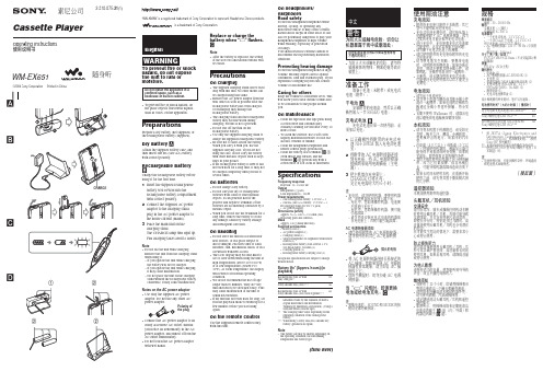
Prepare a dry battery (not supplied) or the rechargeable battery (supplied).
Dry Battery A
Attach the supplied battery case, and then insert one R6 (size AA) battery with correct polarity.
Note
Do not use the unit while charging. Remove the unit from the charging stand when using it. – If you operate the unit while
charging, the battery will not be charged. – If you operate the unit while charging, it may cause malfunction. – Do not place the unit on the charging stand without the rechargeable battery. Otherwise, it may cause malfunction.
索尼M-730V/830V随身听维修手册

M-730V/830VUS Model Canadian ModelAEP Model E ModelM-730V/830VChinese ModelM-730VT ourist ModelM-830VSERVICE MANUALMICROCASSETTE TM-CORDERVer 1.3 2003. 07SPECIFICATIONSModel Name Using Similar Mechanism NEW Tape T ransport Mechanism TypeMZ-730V-99Photo : M-830VSony CorporationPersonal Audio CompanyPublished by Sony Engineering Corporation9-927-100-132003G16-1© 2003.07– 2 –TABLE OF CONTENTSFlexible Circuit Board Repairing•Keep the temperature of the soldering iron around 270˚C during repairing.•Do not touch the soldering iron on the same conductor of the circuit board (within 3 times).•Be careful not to apply force on the conductor when soldering or unsoldering.Notes on Chip Component Replacement •Never reuse a disconnected chip component.•Notice that the minus side of a tantalum capacitor may be dam-aged by heat.1. GENERAL ....................................................................32. DISASSEMBLY2-1.Lid Assy, Cassette ...............................................................42-2.Lid, Battery Case ................................................................42-3.Cabinet (Rear) Assy ............................................................52-4.Speaker Assy, Microphone..................................................52-5.Main Board .........................................................................62-6.Mechanism Deck.................................................................62-7.LED Unit.............................................................................72-8.Head, Creamic (HRPE901, 902) (7)3. MECHANICAL ADJUSTMENTS ..............................84. ELECTRICAL ADJUSTMENTS ...............................85. DIAGRAMS5-1.Block Diagram ..................................................................115-2.Printed Wiring Board ........................................................135-3.Schematic Diagram.. (15)6. EXPLODED VIEWS6-1.Cabinet Section .................................................................176-2.Mechanism Deck Section (1)............................................196-3.Mechanism Deck Section (2).. (20)7. ELECTRICAL PARTS LIST (21)– 3 –SECTION 1GENERAL1 VOL knob2 MIC jack3 EAR jack4 VOR switch5 REC/BATT lamp6 FAST PB switch (M-830V ONLY)7 DC IN 3V jack8 TAPE COUNTER9 CUE MARKER button (M-830V ONLY)0 i (Battery) lamp (M-830V ONLY)!¡ Microphone!™ r (REC) button !£ C PAUSE knob !¢ œ(Playback) button !∞ CUE/REVIEW knob !§ TAPE SPEED select knob !¶ wp (Eject/Stop) button !• DIR c knob !ª FWD/REV∑– 4 –SECTION 2DISASSEMBL Y•The equipment can be removed using the following procedure.Note : Follow the disassembly procedure in the numerical order given.2-1. LID ASSY, CASSETTE2-2. LID, BATTERY CASESet Lid assy, cassetteLED unitLid, battery caseCabinet (rear) assy Speaker assy, MicrophoneMain boardMechanismdeck2– 5 –2-3.CABINET (REAR) ASSYNote : When installing, fit the knobs and switches.2-4. SPEAKER ASSY, MICROPHONE2 Four screws (B1.7 × 16)1 Screw (B1.7 × 5)3 Claw5 Cabinet (rear) assy4 ClawsSwitch(TAPE SPEED)Switch (PAUSE)Knob (PAUSE)Knob(FR)– 6 –2-6. MECHANISM DECK2-5. MAIN BOARD122-7. LED UNIT2-8. HEAD, CERAMIC (HRPE901, 902)Claw– 7 –– 8 –PRECAUTION1.Clean the following parts with a denatured-alcohol-moistenedswab :record/playback/erase head pinch roller rubber belts capstan2.Demagnetize the record/playback/erase head with a head de-magnetizer. (Do not bring the head demagnetizer close to the erase head.)3.Do not use a magnetized screwdriver for the adjustments.4.The adjustments should be performed with the rated power sup-ply voltage unless otherwise noted.Power supply voltage : 3 Vdc TAPE SPEED switch : 2.4cm Torque MeasurementMode Torque Meter Meter Reading 5 to 10 g • cmForward CQ-102M (0.07 to 0.140 oz • inch)5 to 10 g • cmReverse CQ-102MR (0.07 to 0.140 oz • inch)more than 30 g • cm Fast Forward CQ-201M (more than 0.42 oz • inch)more than 30 g • cm RewindCQ-201M(more than 0.42 oz • inch)Tape Tension MeasurementMode Tension Meter Meter Reading more than 25 g Forward CQ-403M (more than 0.35 oz)more than 25 g ReverseCQ-403MR(more than 0.35 oz)SECTION 3MECHANICAL ADJUSTMENTSRecord/Playback/Erase Head Azimuth AdjustmentSetting:VOL control: mechanical mid TAPE SPEED switch : 2.4cm/s VOR switch : OFF FAST PB switch : OFF Procedure:1.Mode : PlaybackAdjustment Location :Test Tape TypeSignalUsed forTape Speed (cm/s) S-2-A030A 3 kHz, – 20 dB Head Azimuth Adjustment 2.4WS-24 3 kHz, – 10 dB Tape Speed Adjustment1.2/2.4SECTION 4ELECTRICAL ADJUSTMENTS2.Turn the adjustment screw to obtain the maximum reading onlevel meter.Note: Several peaks may appear, but the maximum.First remove the cover (AZ).test tape S-2-A030A– 9 –Specification Value:Tape Speed Frequency counter 1.2/2.4 cm/s2,880 to 3,120 HzTape Speed AdjustmentSetting:VOL control : mechanical mid VOR switch : OFFFAST PB switch : ON (M-830V model only)Procedure:•Reform 2.4 cm/s speed adjustment before 1.2 cm/s speed adjust-ment mode : playbackFrequency difference between the beginning and the end of the tapeshould be within ±0.5%.Adjustment Location :First remove the plate, blind.1.Tape Speed :2.4 cm/sPlayback WS-24 (tape center part) and adjust RV601 so that reading on the digital frequency counter becomes 3,000 Hz.2.Tape Speed : 1.2 cm/sPlayback WS-24 (tape center part) and adjust RV602 so thatreading on the digital frequency counter becomes 3,000 Hz.EAR jack (J101)digital frequency countertest tapeRemove the plate, blind.RV602(1.2 cm/s)RV601(2.4 cm/s)Speed adjustable resistors– 10 –• IC Block DiagramsIC101 LA4168MLIC501 MM1251M(M-830V model only)SECTION 5DIAGRAMSIC601 LB1877VP R E G N DE Q I NM I C I NV r e f O U TM I C V C CR , F O U TL E D D R I V ER /P S WP A U S EP /R M U T EG V N C O N TG V N V r e fV sG V N G N DG V N O U T P R E N FP R E O U TR E G I NR E G O U TA L C C O N TV O X C O N TV O X D E L A YG N V S P E E D U PA U T S T O P C O N TA U T S T O P I NP W R I NP W R O U T 1P W R G N DP W R O U T 2V c cU O UTD RV C CL BF CO U TV S P I N +V R E FS /SV O U T W O U TP -G N DW B V B U BO S CC O MG N DR IC C CSY SN C G N O UM-730V/830V– 17 –SECTION 6EXPLODED VIEWSNOTE:•The mechanical parts with no referencenumber in the exploded views are not supplied.•Items marked “*” are not stocked sincethey are seldom required for routine service.Some delay should be anticipated when ordering these items.•-XX and -X mean standardized parts, so they may have some difference from the original one.•Color Indication of Appearance Parts Example :KNOB, BALANCE (WHITE) ... (RED)Parts Color Cabinet’s Color6-1. CABINET SECTIONNN•Accessories and packing materials are given in the last of this parts list.•AbbreviationCND :Canadian model JEW :Tourist model129394354546633433414443637232122203519262527282930403132241838171641421211107MIC901SP901not suppliedRef. No.Part No.Description Remark Ref. No.Part No.Description Remark1A-3050-984-A LID ASSY, CASSETTE (730V)1A-3050-988-A LID ASSY, CASSETTE (830V)2X-3379-038-1CABINET (FRONT) SUB ASSY (830V)2X-3377-343-1CABINET (FRONT) SUB ASSY (730V)33-322-226-71SPACER(A)43-031-649-01KNOB(RV)53-010-503-01SPRING(B), BATTERY COIL63-669-481-07PIN(DIA.1X10), PARALLEL73-031-645-01HOLDER, MIC93-031-653-01CUSHION, MIC101-418-390-11LED UNIT (730V)101-418-391-11LED UNIT (830V)113-031-652-01BRACKET (LED)123-318-382-31SCREW (1.7), TAPPING143-034-792-01SCREW (2X2.5), TAPPING (B)163-031-656-01BUTTON (REC)173-031-655-01BUTTON (PLAY)183-031-654-01BUTTON (STOP)193-704-197-31LOCK, SERRAT IB203-036-882-01SPACER (JACK)213-034-687-01TERMINAL (-), BATTERY223-034-686-01TERMINAL (+), BATTERY233-831-441-99SPACER, KNOB24A-3021-220-A MAIN BOARD, COMPLETE (730V)24A-3021-221-A MAIN BOARD, COMPLETE (830V)25X-3377-334-1CABINET (REAR) ASSY (830V:US,CND,AEP,E)25X-3377-335-1CABINET (REAR) ASSY (830V:JEW)25X-3377-336-1CABINET (REAR) ASSY (730V)263-037-004-01PAPER (A), SHIELD273-031-660-01KNOB(FR)283-035-255-11SCREW (1.7X16)293-358-363-31PLATE, BLIND303-318-203-72SCREW (B1.7X5), TAPPING313-031-662-01LID,BATTERY CASE (830V)313-031-662-11LID,BATTERY CASE (730V)*323-914-930-01CUSHION (BATTERY CASE LID) 333-328-319-01STRAP, HAND343-037-193-01CUSHION (SP)353-037-146-01CUSHION (A)367-623-505-01LUG, 2373-891-132-00SCREW (M1.7X2.0), SPECIAL HEAD*383-037-557-01SHEET (B), GROUND393-039-027-01SPACER (MIC)403-039-501-01SPACER (CABINET REAR)413-039-381-01CUSHION (PLAY)423-039-382-01SPACER (PLAY)433-038-919-01SPACER (COUNTER)443-380-902-21SPACER (FR)454-963-883-61SCREW (M1.4), PRECISION PAN463-037-211-01REINFORCEMENT (MJ)SP9011-529-188-11SPEAKER (3.6cm)MIC9011-542-386-11MICROPHONE, ELECTRET CONDENSER (MIC)Ver 1.3 2003. 07– 18 –6-2.MECHANISM DECK SECTION (1)(MZ-730V-99)Ref. No.Part No.Description Remark Ref. No.Part No.Description Remark513-331-007-21WASHER523-350-989-01WASHER533-028-961-01SPRING (BUTTON), COMPRESSION 563-028-929-01LEVER (POWER SW)573-028-940-02LEVER (SRS)583-028-938-01LEVER (SLIDE)593-578-224-00WASHER60X-3376-227-1LEVER (F/R) ASSY61X-3376-228-1LEVER (TU) ASSY623-029-634-01BEARING63X-3376-231-1FLYWHEEL ASSY643-377-420-11BELT66X-3376-230-1LIMITTER ASSY673-028-955-01SPRING (LOCK), TENSION68X-3377-535-1LEVER (LOCK) ASSY694-992-239-01WASHER (A)*703-028-967-01LEVER (PAUSE RELEASE) 713-028-954-01SPRING (SW LEVER), TENSION 723-321-483-11RING, RETAINING733-028-928-01LEVER (EJECT)743-028-964-01SPRING (SLIDER), TORSION754-926-562-01WASHER, STOPPER763-028-927-01LEVER (STOP)773-028-920-01LEVER (REVERSE SWITCH)78X-3376-236-1LEVER (CLAW DETECTION R) ASSY 793-029-635-01SPRING (LEVER DIR), TORSION 803-029-639-01SPRING, TENSION813-028-932-01LEVER (JOINT)823-028-933-01LEVER (DIR)833-028-905-01GEAR(S-OFF), CAM843-167-330-01WASHER853-028-942-01SPRING (D-LOCK), TORSION863-028-941-01LEVER (DIR-LOCK)873-028-906-01GEAR(REVERSE), CAM88X-3376-224-1LEVER (REC) ASSY80818283848586808751666463 595857566261608853525167687971727369707475767877– 19 –– 20 –1013-703-816-31SCREW (M1.4), SPECIAL HEAD 1023-703-816-73SCREW (M1.4), SPECIAL HEAD1033-028-960-01SPRING (AZIMUTH), COMPRESSION 1043-028-909-01GUIDE (N), TAPE1053-028-965-01SPRING (PINCH ARM), TORSION 108X-3376-232-1LEVER (PLAY) ASSY109X-3376-235-1ARM(PINCH ROLLER) ASSY 1103-321-483-11RING, RETAINING1111-548-579-41COUNTER, TAPE (SMALL TYPE)112X-3376-726-1CHASSIS (COMP) ASSY (R)1133-343-948-01BELTRef. No.Part No.DescriptionRemarkRef. No.Part No.DescriptionRemark 1143-028-922-01BRACKET (N), HEAD115X-3376-234-1BRACKET (R) ASSY, HEAD 1163-028-962-01SPRING, TORSION 1173-028-910-01GUIDE (R), TAPE1183-028-921-01LEVER (HEAD ROTARY)1193-029-808-01BRACKET (MOTOR)1203-365-053-01SHEET (BA), ADHESIVEM9011-763-236-11MOTOR, DC (REEL/CAPSTAN)(WITH PULLY)HRPE9011-500-593-11HEAD, CERAMIC (REC/PB/ERASE)HRPE9021-500-594-11HEAD, CERAMIC (REC/PB/ERASE)6-3.MECHANISM DECK SECTION (2)(MZ-730V-99)M901HRPE901HRPE902108104109101102103114115116110105117103101102119101101101112113120111118– 21 –SECTION 7ELECTRICAL PARTS LISTRef. No.Part No.DescriptionRemark Ref. No.Part No.Description Remark MAINNOTE:•Due to standardization, replacements in the parts list may be different from the parts specified in the diagrams or the components used on the set.•-XX and -X mean standardized parts, so they may have some difference from the original one.•RESISTORSAll resistors are in ohms.METAL:Metal-film resistor.METAL OXIDE: Metal oxide-film resistor.F:nonflammable•Items marked “*” are not stocked sincethey are seldom required for routine service.Some delay should be anticipated when ordering these items.•SEMICONDUCTORSIn each case, u : µ, for example:uA..: µA..uPA..: µPA..uPB..: µPB..uPC..: µPC.. uPD.. : µPD..•CAPACITORS uF : µF •COILS uH : µHWhen indicating parts by reference number, please include the board.A-3021-220-A MAIN BOARD, COMPLETE (730V)*********************A-3021-221-A MAIN BOARD, COMPLETE (830V)*********************< CAPACITOR >C1011-163-989-11CERAMIC CHIP 0.033uF 10%25V C1021-110-501-11CERAMIC CHIP 0.33uF 10%16V C1031-110-501-11CERAMIC CHIP 0.33uF 10%16V C1041-163-017-00CERAMIC CHIP 0.0047uF 5%50V C1051-163-009-11CERAMIC CHIP 0.001uF 10%50V C1061-163-009-11CERAMIC CHIP 0.001uF 10%50V C1071-107-823-11CERAMIC CHIP 0.47uF 10%16V C1081-126-209-11ELECT CHIP 100uF 20%4V C1091-113-690-11ELECT CHIP 220uF 20%4V C1101-135-201-11TANTALUM CHIP 10uF 20%4V C1111-163-009-11CERAMIC CHIP 0.001uF 10%50V C1121-164-182-11CERAMIC CHIP 0.0033uF 10%50V C1131-163-037-11CERAMIC CHIP 0.022uF 10%25V C1141-163-009-11CERAMIC CHIP 0.001uF 10%50V C1151-109-982-11CERAMIC CHIP 1uF 10%10V C1161-164-346-11CERAMIC CHIP 1uF 16V C1191-163-009-11CERAMIC CHIP 0.001uF 10%50V C1201-163-009-11CERAMIC CHIP 0.001uF 10%50V C1211-164-346-11CERAMIC CHIP 1uF 16V C1221-163-009-11CERAMIC CHIP 0.001uF 10%50V C1231-164-005-11CERAMIC CHIP 0.47uF 25V C1241-135-201-11TANTALUM CHIP 10uF 20%4V C1251-135-180-21TANTALUM CHIP 3.3uF 20% 6.3V C1261-164-489-11CERAMIC CHIP 0.22uF 10%16V C1271-164-489-11CERAMIC CHIP 0.22uF 10%16V C1281-163-009-11CERAMIC CHIP 0.001uF 10%50V C1291-126-246-11ELECT CHIP 220uF 20%4V C1301-163-251-11CERAMIC CHIP 100pF 5%50V C1311-163-017-00CERAMIC CHIP 0.0047uF 5%50V C1321-163-038-91CERAMIC CHIP 0.1uF 25V C1331-164-005-11CERAMIC CHIP 0.47uF 25V C1341-124-778-00ELECT CHIP 22uF 20% 6.3V C1351-164-505-11CERAMIC CHIP 2.2uF 16V C1361-124-778-00ELECT CHIP 22uF 20% 6.3V C1371-107-725-11CERAMIC CHIP0.1uF10%16VC1381-163-989-11CERAMIC CHIP 0.033uF 10%25V C1391-135-201-11TANTALUM CHIP 10uF 20%4V C1401-107-823-11CERAMIC CHIP 0.47uF 10%16V C1411-164-161-11CERAMIC CHIP 0.0022uF 10%100V C1421-164-005-11CERAMIC CHIP 0.47uF 25V C1431-163-038-91CERAMIC CHIP 0.1uF 25V C1441-163-017-00CERAMIC CHIP 0.0047uF 5%50V C1451-163-009-11CERAMIC CHIP 0.001uF 10%50V C1461-163-001-11CERAMIC CHIP 220PF 10%50V C1471-163-009-11CERAMIC CHIP 0.001uF 10%50V C1481-163-009-11CERAMIC CHIP 0.001uF 10%50V C1491-163-035-00CERAMIC CHIP 0.047uF 50V C1501-128-014-11ELECT CHIP 10uF 20%4V C1511-104-847-11TANTAL. CHIP 22uF 20%4V C1521-104-847-11TANTAL. CHIP 22uF 20%4V C1541-135-201-11TANTALUM CHIP 10uF 20%4V C1551-164-222-11CERAMIC CHIP 0.22uF 25V C1561-163-251-11CERAMIC CHIP 100pF 5%50V C1571-107-725-11CERAMIC CHIP 0.1uF 10%16V C1581-163-038-91CERAMIC CHIP0.1uF25V C3011-135-170-21TANTALUM CHIP 6.8uF 20%4V(830V)C3021-107-725-11CERAMIC CHIP 0.1uF 10%16V (830V)C3031-107-725-11CERAMIC CHIP 0.1uF 10%16V (830V)C3041-164-489-11CERAMIC CHIP 0.22uF 10%16V (830V)C5011-128-014-11ELECT CHIP10uF20%4V(830V)C5021-107-725-11CERAMIC CHIP 0.1uF 10%16V (830V)C6011-164-344-11CERAMIC CHIP 0.068uF 10%25V C6021-164-344-11CERAMIC CHIP 0.068uF 10%25V C6031-164-344-11CERAMIC CHIP 0.068uF 10%25V C6041-164-489-11CERAMIC CHIP 0.22uF 10%16V C6051-163-809-11CERAMIC CHIP 0.047uF 10%25V C6061-135-149-21TANTALUM CHIP 2.2uF 20%10V C6071-107-823-11CERAMIC CHIP 0.47uF 10%16V C6081-163-017-00CERAMIC CHIP 0.0047uF 5%50V C6091-163-009-11CERAMIC CHIP 0.001uF10%50V< CONNECTOR >CN1011-580-372-41JACK,DC (POLARITY UNIFIED TYPE) (DC IN 3V)•AbbreviationCND :Canadian modelEE :East European model CH :Chinese model JEW :Tourist modelRef. No.Part No.Description Remark Ref. No.Part No.Description Remark< DIODE >D1018-719-422-56DIODE MA8056-H-TX< FERRITE BEAD >FB1011-414-235-22INDUCTOR CHIP0uH< IC >IC1018-759-492-49IC LA4168MLIC5018-759-399-49IC MM1251 (830V)IC6018-759-566-10IC LB1877V< JACK >J1011-785-791-11JACK (MIC)J1021-785-790-11JACK (EAR)< COIL >L5011-412-032-11INDUCTOR CHIP100uH (830V)< TRANSISTOR >Q1018-729-800-37TRANSISTOR 2SD1048-X7Q1028-729-402-84TRANSISTOR XN4601Q1038-729-230-72TRANSISTOR 2SA1362YGQ1048-729-230-63TRANSISTOR 2SC4116-YGQ1058-729-230-63TRANSISTOR 2SC4116-YGQ1068-729-420-44TRANSISTOR UN5210Q1078-729-402-84TRANSISTOR XN4601Q1088-729-403-45TRANSISTOR XN1115Q1098-729-402-96TRANSISTOR UN5114Q1118-729-028-78TRANSISTOR DTA115TUA-T106Q1128-729-230-63TRANSISTOR 2SC4116-YGQ1168-729-230-63TRANSISTOR 2SC4116-YGQ1178-729-402-93TRANSISTOR UN5214-TXQ1188-729-420-44TRANSISTOR UN5210Q1198-729-230-60TRANSISTOR 2SA1586-YGQ1208-729-230-63TRANSISTOR 2SC4116-YGQ3018-729-230-63TRANSISTOR 2SC4116-YG (830V)Q3028-729-402-96TRANSISTOR UN5114 (830V)Q3038-729-230-63TRANSISTOR 2SC4116-YG (830V)Q3048-729-230-63TRANSISTOR 2SC4116-YG (830V)Q3058-729-230-63TRANSISTOR 2SC4116-YG (830V)Q5018-729-230-63TRANSISTOR 2SC4116-YG (830V)Q6018-729-230-60TRANSISTOR 2SA1586-YG (830V)Q6038-729-230-60TRANSISTOR 2SA1586-YG< RESISTOR >R1011-216-061-00METAL CHIP 3.3K5%1/10W R1021-216-061-00METAL CHIP 3.3K5%1/10W R1031-216-069-00METAL CHIP 6.8K5%1/10W R1041-216-057-00METAL CHIP 2.2K5%1/10W R1051-216-025-91RES,CHIP1005%1/10W R1061-216-041-00METAL CHIP4705%1/10W R1071-216-113-00METAL CHIP470K5%1/10W R1091-216-073-00METAL CHIP10K5%1/10W R1101-216-073-00METAL CHIP10K5%1/10W R1111-216-037-00METAL CHIP3305%1/10W R1121-216-057-00METAL CHIP 2.2K5%1/10W R1131-216-081-00METAL CHIP22K5%1/10W R1141-216-061-00METAL CHIP 3.3K5%1/10W R1151-216-089-91RES,CHIP47K5%1/10W R1161-216-017-91RES,CHIP475%1/10WR1171-216-037-00METAL CHIP3305%1/10W R1181-216-093-91RES,CHIP68K5%1/10W R1191-216-049-91RES,CHIP1K5%1/10W R1201-216-073-00METAL CHIP10K5%1/10W R1211-216-113-00METAL CHIP470K5%1/10WR1221-216-049-91RES,CHIP1K5%1/10W R1241-216-097-91RES,CHIP100K5%1/10W R1251-216-121-91RES,CHIP1M5%1/10W R1261-216-041-00METAL CHIP4705%1/10W R1271-216-077-00METAL CHIP15K5%1/10W R1281-216-105-91RES,CHIP220K5%1/10W R1291-216-085-00METAL CHIP33K5%1/10W R1301-216-065-91RES,CHIP 4.7K5%1/10W R1311-216-069-00METAL CHIP 6.8K5%1/10W R1321-216-073-00METAL CHIP10K5%1/10WR1331-216-073-00METAL CHIP10K5%1/10W R1341-216-081-00METAL CHIP22K5%1/10W R1351-216-097-91RES,CHIP100K5%1/10W R1371-216-009-91RES,CHIP225%1/10W R1381-216-009-91RES,CHIP225%1/10W R1391-216-053-00METAL CHIP 1.5K5%1/10W R1401-216-013-00METAL CHIP335%1/10W R1411-216-009-91RES,CHIP225%1/10W R1421-216-073-00METAL CHIP10K5%1/10W R1431-216-073-00METAL CHIP10K5%1/10WR1441-216-089-91RES,CHIP47K5%1/10W R1471-216-069-00METAL CHIP 6.8K5%1/10W R1481-216-089-91RES,CHIP47K%1/10W R1491-216-073-00METAL CHIP10K5%1/10W R1501-216-073-00METAL CHIP10K5%1/10W R1511-216-049-91RES,CHIP1K5%1/10W R1521-216-049-91RES,CHIP1K5%1/10W R1541-216-077-00METAL CHIP15K5%1/10W R1551-216-065-91RES,CHIP 4.7K5%1/10W R1561-216-037-00METAL CHIP3305%1/10WR1571-216-097-91RES,CHIP100K5%1/10W R3011-216-057-00METAL CHIP 2.2K5%1/10W(830V) R3021-216-129-00METAL CHIP 2.2M5%1/10W(830V) R3031-216-113-00METAL CHIP470K5%1/10W(830V) R3041-216-065-91RES,CHIP 4.7K5%1/10W(830V)R3051-216-085-00METAL CHIP33K5%1/10W(830V) R3061-216-065-91RES,CHIP 4.7K5%1/10W(830V) R3071-216-081-00METAL CHIP22K5%1/10W(830V) R3081-216-049-91RES,CHIP1K5%1/10W(830V) R3091-216-057-00METAL CHIP 2.2K5%1/10W(830V)MAIN– 22 –Ref. No.Part No.Description RemarkMAIN Ref. No.Part No.Description RemarkR3111-216-295-91RES,CHIP0 (830V) R3121-216-065-91RES,CHIP 4.7K5%1/10W(830V) R5011-216-037-00METAL CHIP3305%1/10W(830V) R5021-216-021-00METAL CHIP685%1/10W(830V) R5051-216-053-00METAL CHIP 1.5K5%1/10W(830V)R5061-216-049-91RES,CHIP1K5%1/10W(830V) R5071-216-089-91RES,CHIP47K5%1/10W(830V) R5081-216-037-00METAL CHIP3305%1/10W(830V) R5091-216-073-00METAL CHIP10K5%1/10W(830V) R5101-216-089-91RES,CHIP47K5%1/10W(830V)R5111-216-105-91RES,CHIP220K5%1/10W(830V) R5121-216-109-00METAL CHIP330K5%1/10W(830V) R6011-216-097-91RES,CHIP100K5%1/10W R6021-216-073-00METAL CHIP10K5%1/10W R6031-216-065-91RES,CHIP 4.7K5%1/10WR6051-216-121-91RES,CHIP1M5%1/10W R6061-216-121-91RES,CHIP1M5%1/10W R6071-216-121-91RES,CHIP1M5%1/10W R6081-216-085-91RES,CHIP33K5%1/10W R6091-216-073-00METAL CHIP10K5%1/10WR6101-216-097-91RES,CHIP100K5%1/10W R6111-216-077-00METAL CHIP15K5%1/10W R6121-216-065-91RES,CHIP 4.7K5%1/10W R6131-216-081-00METAL CHIP22K5% 1/10W(830V) R6141-216-097-91RES,CHIP100K5%1/10W(830V)R6151-216-065-91RES,CHIP 4.7K5%1/10W R6161-216-113-00METAL CHIP470K5%1/10W(830V) R6171-216-073-00METAL CHIP10K5%1/10W R6181-216-081-00METAL CHIP22K5%1/10W R6191-216-065-91RES,CHIP 4.7K5%1/10W< VARIABLE RESISTOR >RV1011-237-731-21RES, VAR, CARBON 10K (VOL )RV6011-223-585-11RES, ADJ, CARBON 4.7KRV6021-223-585-11RES, ADJ, CARBON 4.7K< SWITCH >S1011-572-964-11SWITCH, SLIDES1021-692-605-31SWITCH, SLIDE (VOR)S1031-762-594-41SWITCH, PUSH (1 KEY) (POWER)S6011-572-922-31SWITCH, SLIDE (FAST PB) (830V)S6021-571-277-51SWITCH, SLIDE (TAPE SPEED)S6031-572-922-31SWITCH, SLIDE (PAUSE)S6041-572-688-11SWITCH, PUSH (1 KEY) (DIR)< THERMISTOR(POSITIVE) >THP6011-810-794-11THERMISTOR, POSITIVE************************************************************MISCELLANEOUS***************101-418-390-11LED UNIT (730V)101-418-391-11LED UNIT (830V)HRPE9011-500-593-11HEAD, CERAMIC (REC/PB/ERASE)HRPE9021-500-594-11HEAD, CERAMIC (REC/PB/ERASE)M9011-763-236-11MOTOR, DC (REEL/CAPSTAN)(WITH PULLY) MIC9011-542-386-11MICROPHONE, ELECTRET CONDENSER (MIC) SP9011-529-188-11SPEAKER (3.6cm)************************************************************ACCESORIES & PACKING MATERIALS*******************************3-031-650-01COVER(AZIMUTH) (830V)3-035-588-01CASE,CARRYING (730V:AEP,EE,830V)3-229-699-11MANUAL, INSTRUCTION (ENGLISH) (830V:US)3-229-699-21MANUAL, INSTRUCTION (SPANISH) (830V:US)3-865-289-11MANUAL, INSTRUCTION (JAPANESE) (JEW)3-865-289-21MANUAL, INSTRUCTION (ENGLISH) (US,CND)3-865-289-31MANUAL, INSTRUCTION (FRENCH) (CND,AEP)3-865-289-41MANUAL, INSTRUCTION(ENGLISH/SPANISH/PORTUGUESE/ITALIAN) (AEP,E) 3-865-289-51MANUAL, INSTRUCTION(GERMAN/DUTCH/SWEDISH/FINNISH) (AEP) 3-865-289-61MANUAL, INSTRUCTION(ENGLISH/SIMPLIFIED CHINESE/HUNGARIAN/RUSSIAN)(EE,CH,JEW) 3-865-289-71MANUAL, INSTRUCTION(TRADITIONAL CHINESE/KOREAN/POLISH/CZECH)(EE,JEW) 3-865-289-81MANUAL, INSTRUCTION(ENGLISH/TRADITIONAL CHINESE) (730V:E) 8-952-251-90HEADPHONE MDR-E122 SET (830V:JEW)∑Ver 1.2 2001. 02– 23 –M-730V830VREVISION HISTORYClicking the version allows you to jump to the revised page.Also, clicking the version at the upper right on the revised page allows you to jump to the next revised page.Ver.Date Description of Revision1.01999.04New1.12000.01Change of mechanical parts.1.22001.02Addition of mechanical parts.1.32003.07Correction of Part No. of Ref. No. 2 (830V)(ENG-00001)。
最新SONY贴片机的维护与使用

S O N Y贴片机的维护与使用威海职业学院毕业设计任务书专业应用电子技术专业年级2007班级(1)班姓名王宇学号 20070203051威海职业学院教务处编印答辩情况记录毕业设计应完成的图纸;;图2-1 SONY贴片机 (见10页)图2-2DR功能原理圖 (见12页)图-3 DW功能原理图(见13页)图2-4 LC框架图 (见13页)图2-5 CC板卡连线图 (见14页)图3- 1SONY贴片机操作界面 (见17页) 图3-2菜单结构 (见18页)图3-3手动操作 (见19页)图4-1 SONY贴片机的保养 (见25页) 图4-2 SONY贴片机的头部' (见25页)图4-3 SONY贴片机的Y轴排线 (见26页)SONY贴片机的使用与维护摘要目前SMT已经成为现代电子产品的PCB电路组件级互联的主要技术手段。
相关资料表明,发达国家的SMT应用普及率已超过75%,并进一步向高密度组装、立体组装等技术为代表的组装技术领域发展。
组装技术的不断发展必将对组装工艺及相关设备的发展提出新的要求。
如何缩短运行时间、加速转换时间,以及不断地引入具有大量的引脚数量和精细问距的元器件成了如今的贴装设备所面临的严峻挑战。
正因为如此,所以选择合适的贴装设备以满足现如今的应用需要足。
贴片机是用来实现高速、高精度地全自动地贴放元器件的设备,是整个SMT、生产中最关键、最复杂的设备。
贴片机是SMT的生产线中的主要设备,现在,贴片机已从早期的低速机械贴片机发展为高速光学对中贴片机,并向多功能、柔性连接模块化发展。
近年来,新型电子表面贴装技术SMT(Surface Mount Tech-nology)已取代传统的通孔插装技术,并支配电子设备发展,被共识为电子装配技术的革命性变革。
SMT以提高产品可靠性及性能,降低成本为目标,无论是在消费类电子产品,还是在军事尖端电子产品领域中,都将使电子产品发生重大变革。
目录前言 (6)第一章了解贴片机 (7)1.1 SMT的概述及优点 (7)1.2 贴片机在SMT中的作用 (8)第二章 SONY贴片机的介绍 (10)2.1 SONY贴片机的概述 (10)2 .2贴装头的运动及其原理介绍 (10)2.3 SONY贴片机的控制板卡 (11)2.4 步进马达与交流伺服马达 (14)第三章SONY贴片机的操作 (17)3.1 SONY贴片机的操作界面 (17)3.2 SONY贴片机基本操作 (19)3.3 SONY贴片机不良及处理对策 (22)第四章 SONY贴片机的维护 (25)4.1 SONY贴片机的保养 (25)4.2 SONY贴片机的常见故障及处理对策 (26)第五章总结 (29)致谢 (30)前言sony新一代小型高速电子元件贴片机G系列【SI‐G200】,其搭载全新两种高速行星贴片接头及新开发之多功能行星接头,能更快速、精密的有效提升产能。
sonyCD随身听全解

1984年爱迪生发明电声技术之后的100多年里,唱片技术每隔25年就有一次大的技术革新。
从圆筒方式进入圆盘唱片,到电气式唱盘的登场,再进入LP唱片,再从单音进入立体声。
在第100年里,数字音频技术产生了。
1982年8月31日傍晚,日本各大媒体都争相报导“引发音频之梦的数字Player终于上市”、“数字音频时代开幕”等消息。
原来,当天SONY、CBS/SONY、荷兰飞利浦与POLYGRAM四家公司共同举办了CD这个数字录音格式的发布会,并决定从秋季起开始在日本发售。
直径仅仅12cm,利用数字信号录音,只要一个按钮就可执行选曲,能够半永久的使用,CD实现了许多乐迷的梦想。
是年10月1日,SONY推出了第一台CD机CDP-101。
168,000日圆的价格,对一般消费者而言是很难接受的。
不过只要想到里面的技术与开发时间,能做成商品的确是一个奇迹。
进入1983年后,其它公司的CD机也相继上市,销售形势一片大好。
但是,接下来的一年里CD市场却陷于停滞状态。
原来,当时购买CD系统的人是以Hi-Fi发烧友为主,大部分的人依旧偏好已融入生活的LP。
为了拯救这种颓势,SONY公司通用音响事业部的大曾根幸三,拿了一个边长13.4cm 的四方型、约4张CD盒厚度的木盒对属下说:“接下来就尝试做这种CD Player吧。
”每个人听到大曾根的目标后,都不禁的怀疑自己的耳朵是不是听错了,不过他的做事风格就是如此,因此没有人感觉到这是一个艰难的任务。
对于SONY的产品开发人员来说,这个木盒就代表着使用者的需求,就象他们自己说的,“将技术汇总起来后,不知道可不可以做成这种尺寸?看来是不行的。
不过只有这个尺寸,才是能让每个人都欣喜的产品”。
为了让CD达到普及化阶段,SONY公司订定出了这样的方针:“价格不可超过5万日圆,最初虽然会出现赤字,不过日后一定会赚钱的。
”这样的价格是CDP-101那168,000日圆的1/3左右。
实际上,5万日圆的价格,赤字率高达200%。
索尼随身听维修手册sony_d-vj85_ver1.0

Model Name Using Similar Mechanism D-E880/EJ815CD Mechanism T ype CDM-3022EBA Optical Pick-up NameDAX-22ESERVICE MANUALE Model Chinese ModelD-VJ85PORTABLE VIDEO CD PLAYERSystemCompact disc digital audio/video system Laser diode propertiesMaterial: GaAlAsWavelength: λ = 780 nmEmission duration: ContinuousLaser output: Less than 44.6 µW (This output is the value measured at a distance of 200 mm from the objective lens surface on the optical pick-up block with 7 mm aperture.)Error correctionSony Super Strategy Cross Interleave Reed Solomon Code D-A conversion1-bit quartz time-axis control Channel number2 channelsFrequency response20 - 20,000 Hz +1/–2 dB (measured by EIAJ CP-307)Output (at 4.5 V input level)Audio output (stereo minijack)Output level 0.7 V rms at 47 kilohms Recommended load impedance over 10kilohmsVideo output (minijack)Output level 1 Vp-p at 75 ohmsRecommended load impedance 75 ohms Headphones (stereo minijack)Approx. 5 mW + Approx. 5 mW at 16 ohmsSPECIFICATIONSPower requirementsFor the area code of the model you purchased, check the upper left side of the bar code on the package.•Two LR6 (size AA) batteries: 3 V DC •AC power adaptor (DC IN 4.5 V jack):E model: 220 - 230 V , 50/60 Hz CH model: 220 V , 50 Hz HK model: 220 V , 50/60 Hz•Two Sony NH-WM2AA rechargeable batteries: 2.4 V DC•Two Sony NC-WMAA rechargeable batteries: 2.4 V DC•Sony DCC-E245 car battery cord for use on car battery: 4.5 V DCBattery life * (approx. hours)(When you use the VIDEO CD player on a flat and stable surface.)Playing time varies depending on how the CD player is used.VIDEO CD Audio CD Two NC-WMAA 110(charged forabout 4 hours **)NH-WM2AA 320(charged forabout 4 hours **)Two Sony alkaline 335batteries LR6SG *Measured value by the standard of EIAJ (Electronic Industries Association of Japan).**Charging time varies depending on how the rechargeable battery is used.Operating temperature5°C - 35°C (41°F - 95°F)Dimensions (w/h/d)(excluding projecting parts and controls)Approx. 131.5 × 25.2 × 141.4 mm (5 1/8 × 3/4 × 5 1/8 in.)MassApprox. 239 g (8.4 oz)(excluding rechargeable batteries)Approx. 298 g (10.5 oz)(including rechargeable batteries and a CD)Design and specifications are subject to change without notice.Supplied accessoriesAC power adaptor AC-E455F (1) (E)AC power adaptor AC-E455 (1) (CH, HK)Audio cable (1)Video cable (1)Wireless remote control RMT-DV11 (1)Earphones with remote controlRM-CD12EL (1) + MDR-E805SP (1)Rechargeable batteries NC-WMAA (2)Battery carrying case (1)Carrying case (1)•AbbreviationCH: Chinese model HK: Hong Kong modelVer 1.0 2000. 03CAUTIONUse of controls or adjustments or performance of proce-dures other than those specified herein may result in haz-ardous radiation exposure.Flexible Circuit Board Repairing•Keep the temperature of the soldering iron around 270°C during repairing.•Do not touch the soldering iron on the same conductor of the circuit board (within 3 times).•Be careful not to apply force on the conductor when soldering or unsoldering.Notes on Chip Component Replacement •Never reuse a disconnected chip component.•Notice that the minus side of a tantalum capacitor may be damaged by heat.This Compact Disc player is classified as a CLASS 1LASER product.The CLASS 1 LASERPRODUCT table is located on the bottom exterior.SAFETY-RELATED COMPONENT WARNING!!COMPONENTS IDENTIFIED BY MARK 0 OR DOTTED LINE WITH MARK 0 ON THE SCHEMATIC DIAGRAMS AND IN THE PARTS LIST ARE CRITICAL TO SAFE OPERATION.REPLACE THESE COMPONENTS WITH SONY PARTS WHOSE PART NUMBERS APPEAR AS SHOWN IN THIS MANUAL OR IN SUPPLEMENTS PUBLISHED BY SONY.NOTES ON HANDLING THE OPTICAL PICK-UP BLOCK OR BASE UNITThe laser diode in the optical pick-up block may suffer electro-static breakdown because of the potential difference generated by the charged electrostatic load, etc. on clothing and the human body.During repair, pay attention to electrostatic breakdown and also use the procedure in the printed matter which is included in the repair parts.The flexible board is easily damaged and should be handled with care.Precautions for Checking Emission of Laser DiodeLaser light of the equipment is focused by the object lens in the optical pick-up so that the light focuses on the reflection surface of the disc. Therefore, be sure to keep your eyes more then 30 cm apart from the object lens when you check the emission of laser diode.Before Replacing the Optical Pick-Up BlockPlease be sure to check throughly the parameters as par the “Opti-cal Pick-Up Block Checking Procedures” (Part No.: 9-960-027-11) issued separately before replacing the optical pick-up block.Note and specifications required to check are given below.•FOK output : IC601 eg pinWhen checking FOK, remove the lead wire to disc motor.•RF signal P-to-P value : 0.35 - 0.65 Vp-pLaser Diode Checking MethodsDuring normal operation of the equipment, emission of the laser diode is prohibited unless the upper lid is closed while turning ON the S801. (push switch type)The following two checking methods for the laser diode are operable.•Method:Emission of the laser diode is visually checked.1.Open the upper lid.2.With a disc not set, turn on the S801 with a screwdriver having a thin tip as shown in Fig.1.or TAP802 is shorted as shown in Fig.2.Note:Do not push the detection lever strongly, or it may be bentor damaged.3.Press the u button.4.Observing the objective lens, check that the laser diode emits light.When the laser diode does not emit light, automatic power control circuit or optical pickup is faulty.In this operation, the objective lens will move up and down 5times along with inward motion for the focus search.Fig. 1TABLE OF CONTENTS1. GENERALGetting started (4)Playing a VIDEO CD (4)Playing an audio CD (5)2. DISASSEMBLY2-1. Cabinet (Lower) Assy (6)2-2. Lid Assy, Upper (6)2-3. Switch Board (7)2-4. MD Assy (7)2-5. Main Board, IR Board (8)2-6. Optical Pick-up (8)3. TEST MODE3-1. How to Enter the Test Mode (9)3-2. How to Release the Test Mode (9)3-3. Each Key Function in Test Mode (9)4. ELECTRICAL ADJUSTMENT4-1. Focus Bias Check (11)5. DIAGRAMS5-1. IC Pin Descriptions (12)5-2. Block Diagram –CD Section (1/2)– (17)5-3. Block Diagram –CD Section (2/2)– (19)5-4. Block Diagram –Video Section– (21)5-5. Block Diagram –Power Supply Section– (23)5-6. Printed Wiring Boards (25)5-7. Schematic Diagram –Main Section (1/4)– (29)5-8. Schematic Diagram –Main Section (2/4)– (31)5-9. Schematic Diagram –Main Section (3/4)– (33)5-10. Schematic Diagram –Main Section (4/4)– (35)6. EXPLODED VIEWS6-1. Cabinet Section (41)6-2. CD Mechanism Deck Section (42)7. ELECTRICAL PARTS LIST (43)SECTION 1GENERALThis section is extracted from instruction manual.Locating the ControlsFor details, see pages in parentheses.CD player (front)Getting startedRemote controlNoteUse only the supplied remote control. You cannot operate this VIDEO CD player with the remote control supplied with other VIDEO CD players.(Front)(Rear)clip.CD player (rear)Wireless remote controlmodel.21, 22, 23)(Continued)Playing a VIDEO CDYou can play back a VIDEO CD, using the supplied AC power adaptor. You can also use rechargeable batteries and alkaline batteries. (See “Connecting a power source ” on pages 28 –30.)To produce color pictures normally, you need to set the color system properly according to theDo this Press u .Press x /CHG (x ).Press uPress > repeatedly until you find the scene or track.Press . repeatedly unitl you find the scene or track.Press the number button of the track (wireless remote control only).Press . or > and hold it down until m or M appears on the TV screen.To Pause StopResume play after pauseLocate the next or succeeding tracks Locate the current or preceding tracks Locate a specific track directlyLocate a point in the track while monitoring the picture**To return to normal playback, press u .The above operations can also be done with the buttons on the supplied earphones with remote control or wireless remote control.About the display•No indication appears on the display while you operate the unit with the wired remote control.•During play, the track number and the elapsed playing time of the current track appear.•During pause, the elapsed playing time flashes.If the volume level does not increase (when listening with the headphones/earphone)Is A VLS set to “LIMIT ”? Set A VLS to “NORM.” For details, see “To protect your hearing (A VLS)” on page 24.If a cable is connected to the AUDIO OUT jack, you cannot adjust the volume. In such a case,disconnect the cable.Removing the VIDEO CDPlaying an audio CDYou can also use rechargeable batteries, alkaline batteries and a car battery. (See “Connecting aheard.Press ux /CHG (x )u. once**. repeatedly**> once**> repeatedly**Number buttons of the track (wireless remote control only)**Hold down >**Hold down .**To Pause StopResume play after pauseFind the beginning of the current track (AMS*)Find the beginning of previous tracks (AMS)Find the beginning of the next track (AMS)Find the beginning of succeeding tracks (AMS)Locate a specific track directly Go forward quickly Go backwards quickly *Automatic Music Sensor**These operations are possible during both play and pause.The above operations can also be done with the buttons on the supplied earphones with remote control or wireless remote control.If you press REPEAT/ENTER (RPT/ENT) to display “REPEAT ”, you can locate the tracks continuously in the following order:•When using >: next track t next track ...... last track t first track t second track ......•When using .: previous track t previous track ...... first track t last track ......About the display•When playing an audio CD using the AC power adaptor, indications on the remote controldisplay window go off until the sound is heard.•When you press u , the total number of tracks in the audio CD and total playing time appear for about two seconds.•During play, the track number and the elapsed playing time of the current track appear.•Between tracks, the time to the beginning of the next track appears with the “-” indication.•During pause, the elapsed playing time flashes.If the volume level does not increaseIs A VLS set to “LIMIT ”? Set A VLS to “NORM.” For details, see “To protect your hearing (A VLS)” on page 24.If a cable is connected to the AUDIO OUT jack, you cannot adjust the volume. In such a case,disconnect the cable.Removing the audio CD3 boss2 boss1 screw (M1.4), step4 lid assy, upperlid, battery caseclaws7 claws6 claw4 claws8 CN8013 claws5 claws2 screws (B2)1 screws (B2)9cabinet (lower) assy • The equipment can be removed using the following procedure.2-2. LID ASSY, UPPERSECTION 2DISASSEMBL YNote : Follow the disassembly procedure in the numerical order given.2-1. CABINET (LOWER) ASSYSetCabinet (Lower) AssyLid Assy, Upper Switch BoardMain Board, IR Board Optical Pick-up4SWITCH board2-3. SWITCH BOARD 2-4. MD ASSY36 optical pick-up2 rack1 M1.4x1.83 M1.4x45 shaft, standard4 bracket assy, sled2-5. MAIN BOARD, IR BOARD2-6. OPTICAL PICK-UPSECTION 3TEST MODE3-1. OUTLINEThis set has the test mode in which the pick-up can be operational checked and the video signal can be verified.3-2. PICK-UP OPERATIONAL CHECKS3-2-1. Setting the test mode 1.Switch positionsOPEN switch (S801): OPEN HOLD switch (S804): OFF A VLS switch (S893): OFF2.Short the TEST terminal TAP801 (TEST) by soldering it.Remove the solder from the TAP901 (V-TEST) and open the terminal.3.Supply4.5 V DC from the DC jack (J401).3-2-2. Releasing the test mode1.Open the TEST terminal TAP801 (TEST) and short the TAP901 (V-TEST).2.Turn the power OFF.3-2-3.Operational checks1.When a specific key is operated:KEYContents of the operation.((LCD DISPLAY))u Spindle on. Tracking servo off.((UP 00 03))x All servo off. Mute on.CHG ((10 different displays are repeatedly presented.))Moves the pick-up to the outside (with the open >switch open). Tracking servo off. Mute on.NEXT((Among 10 different displays, the display when the key is pressed is held.))Moves the pick-up to the inside (with the open.switch open). Tracking servo off. Mute on.PREV((Among 10 different displays, the display when the key is pressed is held.))2.In play mode • Press the u key:KEYContents of the operation.((LCD DISPLAY))Tracking servo on. Mute off.Each time this key is pressed, the display changes PLAY as follows:MODEx1 speed t x2 speed t x3 speed t x4 speed t x1 speed(( 01 00 01)) t ((02 00 02)) t ((03 00 03))t ((04 00 04))Each time this key is pressed, the display changes SELECT as follows:REPEAT/Tracking gain up. Emphasis on. LCD back light ENTERon h Tracking gain down. Emphasis off.LCD back light off3-3. VIDEO SIGNAL VERIFICATION3-3-1. Setting the test mode 1.Switch positionsOPEN switch (S801): OPEN HOLD switch (S804): OFF A VLS switch (S893): OFF2.Short the TEST terminal TAP801(TEST) by soldering it.Remove the solder from the TAP901(V-TEST) and connect the terminal to the TP945 (VDD) with a 47 k Ω resistor.3.Supply 4.5V DC from the DC jack (J401).3-3-2. Releasing the test mode1.Open the TEST terminal TAP801(TEST). Remove the resistor from the TAP901 (V-TEST) and short the terminal by soldering it.2.Turn the power OFF.3-3-3. Operational checks1.Connect the TP931 to the TP945 (VDD) with a 47 k Ω resistor (NTSC mode).2.Press the O RETURN key once.3.Verify that a 100% white pattern is output from the VIDEO OUT (J901).4.Press the O RETURN key once (output off).5.Connect the TP931 to the TP919 (GND) (PAL mode).6.Press O RETURN key once.7.Verify that a 100% white pattern is output from the VIDEO OUT (J901).8.Press the O RETURN key once (output off).9.Open the TP931.Fig. 100% white patternAdjustment Location: See page 10.Test Points:– main board (side A) –– main board (side B) –1. 2. 3. 4.5.•SECTION 4 ELECTRICAL ADJUSTMENTCD section adjustments are done automatically in this set.1.2.3.A•Test Points:– 11 –SECTION 5DIAGRAMS5-1. IC PIN DESCRIPTIONS• IC801 TMP88CM22F (SYSTEM CONTROLLER)Pin No.Pin Name I/O Pin Description1VSS I Ground2IRRMC I Infrared remote control signal input3FOKI I Focus OK signal input from CXD3027R (IC601).4AGCCON O AGC control pulse output5XLEDDISP O CHG/HOLD LED control signal output6VCC SWITCHING O Control signal output for Switching power supply circuit.7AMUTE O Analog audio muting ON/OFF signal control signal output (H: Mute ON)8VCC2 ON O VCC2 voltage control output9XRST O Reset signal output to CXD3027R (IC601). (L: Reset)10SCK O Serial data transfer clock signal output to CXD3027R (IC601).11SDTI I Serial data input from CXD3027R (IC601).12SDTO O Serial data output to CXD3027R (IC601).13SLPOUT O WAKE-UP control signal output (for system standby reset)14SEL I Plug-in detection signal input of AUDIO OUT (OPTICAL) jack.15CHGMNT1I Battery charge voltage detection input from TB2119F (IC401).16VCDKEY I VCD key input17BATMNT I Battery voltage detection input18KEY I Key input from switch board (A/D input).19RMKEY I Key input from headphones with remote controller (A/D input).20DCINMNT I DC input voltage detection input (A/D input) DC input jack use/no-use detect input 21OPEN I CD door open/close detection input22VREFL I Reference voltage (0 V) input for A/D converter.23VREFH I Reference voltage (+2 V) input for A/D converter.24VDD—Power supply pin (+2 V)25SCOR I Sub code sync detection input from CXD3027R (IC601).26GRSCOR I GRSCOR signal input27FG I FG pulse input28BEEP O Beep sound output to headphone AMP (IC351).29XU TX REQ O Request signal output to TMP87PM41U (IC902).30RMSCK O Communication clock to CXD751-103R (IC802) and TMP87PM41U (IC902).31RMDATI I Communication data bus input from CXD751-103R (IC802) and TMP87PM41U (IC902).32RMDA TO O Communication data bus output to CXD751-103R (IC802) and TMP87PM41U (IC902).33RMRW O Read/write control signal output to headphones with remote. (L: Read, H: Write) 34RMLAT O Serial data latch pulse output to headphones with remote.35WFCKI I WFCK input36NC—Not used. (Open)37XNTSC I I NTSC/PAL select input (“L”: PAL, “H”: NTSC)38A VLS I A VLS (Automatic V olume Limiter System) switch input (L: Normal, H: Limit) 39HOLD I HOLD switch input (L: HOLD on, H: HOLD off)40EX BATT I EXT BATT plug-in detection input41XSPDOE O Spindle motor driver control signal output42XHGON O Optical pick-up VCC control signal output (L: on)43XLAT O Serial data latch pulse output to CXD3027R (IC601). (for ESP)44XSOE O Output enable signal output (for ESP)45DRVLT O Spindle motor driver latch output46XPOWLT O Latch output to VCD control IC.47XDOUTON O DIGITAL OUT LED control signal output48XAPC OFF O APC mute signal output (L: mute)49XVRST O Reset signal output to TMP87PM41U (IC902).50 – 52SEG14 – 12O LCD drive segment output53 – 56SEG11 – 8O LCD drive segment output– 12 –Pin No.Pin Name I/O Pin Description57 – 64SEG7 – 0O LCD drive segment output65 – 68COM3 – 0O LCD drive common output69 – 71V3 – 1O LCD drive bias output72, 73C1, 0O Capacitor connected terminal of LCD driver for voltage-up.74STOP O Stop signal output to VCD control IC.75TEST I Test terminal for IC. (Fixed at L in this set)76XHPSW O Headphone AMP ON/OFF control signal output (L: ON) 77XLIGHT O LCD back light control signal output to LCD.78RESET I System reset signal input from TB2119F (IC401). (L: Reset) 79XIN I Oscillation input80XOUT O Oscillation output (Open)– 13 –• IC902 TMP87PM41U (MICON VIDEO ENCODER/VIDEO CONTROLLER)Pin No.Pin Name I/O Pin Description1 – 8P00 – 07—Not used. (Open)9(INT0) P10—Not used. (Open)10(INT1) P11—Not used. (Open)11(INT2/TC1) P12—Not used. (Open)12(DVO) P13—Not used. (Open)13(PPG) P14—Not used. (Open)14(TC2) P15—Not used. (Open)15P16—Not used. (Open)16P17I Visual system test mode pin (“L”: Test mode)17P20 (INT5/STOP)I Interruption request signal input from CL680T-D1 (IC906).18TEST I Test pin (Fixed at “L” in this set)19P21 (XTI)—Not used. (Open)20P22 (XTOUT)—Not used. (Open)21RESET I I System reset signal input from TMP88CM22F (IC801). (“L”: Reset) 22XIN I I High frequency oscillator input from TMP88CM22F (IC801).23XOUT O High frequency oscillator output (Not used in this set)24VSS—Digital ground25P30O CD DA/CD ROM judgment output (“L”: Audio CD)26 – 30P31 – 35—Not used. (Open)31——Not used. (Open)32 C RESET O Reset signal output to CL680T-D1 (IC906). (“L”: Reset)33P40O Ready signal output to CL680T-D1 (IC906).34P41O Address select signal output to CL680T-D1 (IC906).35P42 (SCK1)O Serial clock signal output to CL680T-D1 (IC906).36P43 (SI1)I Serial data signal input from CL680T-D1 (IC906).37P44 (SO1)O Serial data signal output to CL680T-D1 (IC906).38P45 (SCK2)I Serial clock signal input from TMP88CM22F (IC801).39P46 (SI2)I Serial data signal input from TMP88CM22F (IC801).40P47 (SO2)O Serial data signal output to TMP88CM22F (IC801).41P50 (INT3/TC3)I Request signal input from TMP88CM22F (IC801).42P51 (INT4/TC4)I Ready signal input from TMP88CM22F (IC801).43P52 (PWM/PDO)O Request signal output to TMP88CM22F (IC801).44P53 (HPWM0)—Not used. (Open)45P54 (HPWM1)—Not used. (Open)46A VSS—Not used. (Open)47A VREF—Not used. (Open)48(AIN0) P60—Not used. (Open)49(AIN1) P61—Not used. (Open)50(AIN2) P62—Not used. (Open)51(AIN3) P63—Not used. (Open)52(AIN4) P64—Not used. (Open)53(AIN5) P65—Not used. (Open)54(AIN6) P66—Not used. (Open)55(AIN7) P67—Not used. (Open)56VDD—Digital power supply pin (+3.2 V)57(AIN10) P70—Not used. (Open)58(AIN11) P71—Not used. (Open)59(AIN12) P72—Not used. (Open)60(AIN13) P73—Not used. (Open)61(AIN14) P74—Not used. (Open)62(AIN15) P75—Not used. (Open)63(AIN16) P76—Not used. (Open)64(AIN17) P77—Not used. (Open)– 14 –– 39 –IC601 CXD3027RA9A8A7DVSS V D D C O U M I R D F C F O P W M L O C H P H P H P V D D C 17M D M D S S T S F D S R D T F D T R D F F D F R D V S S T E S T E S A V D D I G E A V S S R F D O E C A S 2301W E R A S 1110V D D 0123V D D 2O U T 2I N 2O U T 2V S S 2V S S 1O U T 1I N 1O U T 1V D D 1V S S T A O T A I V D D C K IA6A5A4XWRE XRDE XEMP XWIH XQOK AMUTE SDTI XQCK SCSY SCOR VSS0SBSO EXCK XRST SYSM SDTO XLAT CLOK SENS SCLK XSOE ATSK R4MBCK PCMDI PCMD LRCKI LRCK DOUT VDD2WFCK C2PO GFS XPCK XUGF WDCK VSS2XTSL AVDD3ASYO ASYI BIAS RFAC AVSS3CLTV PCO FILI FILO VCTL VPCO VC A B– 40 –IC351 TA2120FNBEEP NFOUTSWGNDOUTINDETATT MT MT PW BIASBST BST IC802 CXD751-103RIC803 TC7W53FU (TE12R)O 26O 27C C S S 2S B W S E L 2S E L 2V S S X L T S O S C K R E S E L 2L T– 41 –SECTION 6EXPLODED VIEWSRef. No.Part No.DescriptionRemark6-1. CABINET SECTIONRef. No.Part No.DescriptionRemarkNOTE:•The mechanical parts with no referencenumber in the exploded views are not supplied.•Accessories and packing materials are given in the last of this parts list.•Items marked “*” are not stocked sincethey are seldom required for routine service.Some delay should be anticipated when ordering these items.The components identified by mark 0 or dotted line with mark 0 are critical for safety.Replace only with part number specified.1X-4952-439-1CABINET (LOWER) SUB ASSY 24-225-414-01LID, BATTERY CASE 34-908-792-91SCREW (B2)44-224-048-01FOOT, RUBBER54-225-413-01WINDOW (RAY CATCHER)64-224-020-01KNOB (HOLD)*71-676-499-11IR BOARD8A-3323-414-A MAIN BOARD, COMPLETE94-225-416-01TERMINAL SPRING (–), BATTERY 104-225-417-01PLATE, CHARGE DETECTION 114-225-415-01TERMINAL BOARD (+), BATTERY 124-908-792-51SCREW (B2)133-318-382-01SCREW (1.7X3), TAPPING 144-225-407-01LEVER, DETECTION 154-224-229-01SPACER (A)16X-4952-438-1OPEN ASSY 174-224-016-01KNOB (OPEN)184-224-015-01BUTTON (VOL)19X-4952-437-1CABINET (UPPER) SUB ASSY 20X-4952-436-1PLATE ASSY, ORNAMENTAL 213-345-710-21SCREW (M1.4X3) TAPPING 22X-4952-435-1LID SUB ASSY, UPPER 234-224-230-01SPACER (B)243-043-558-01SPRING (B) (OPEN)25X-4952-205-1ARM ASSY, SWITCHING *261-674-587-21SWITCH BOARD274-224-053-01SCREW (M1.4), STEP 284-221-927-01INSULATOR293-375-114-51SCREW303-042-766-11CUSHION (BATT)313-318-201-51SCREW (B) (1.4X4), TAPPING 323-318-382-01SCREW (1.7X3), TAPPING 333-045-650-01SHEET, RADIATION343-044-559-01RAIL354-225-396-01SPACER (C)*361-678-339-11WAKE BOARD– 42 –51525354555657575859606162636465M902M9016-2. CD MECHANISM DECK SECTION(CDM-3022EBA)Ref. No.Part No.DescriptionRemark Ref. No.Part No.DescriptionRemark51A-3328-418-A CHASSIS ASSY (INCLUDING M902)524-220-645-01SHAFT, STANDARD 053X-4952-079-1DAX-22E RP ASSY 544-220-646-01RACK553-704-197-92SCREW (M1.4X1.8), LOCKING56X-4951-687-1BASE ASSY, SLED573-348-998-61SCREW (M1.4X4), TAPPING, PAN584-220-648-01GEAR (C)593-338-645-31WASHER (0.8-2.5)60A-3328-298-A SCREW ASSY, FEED61A-3328-299-AMOTOR BLOCK ASSY , SLED(INCLUDING M901)624-964-564-01SCREW (M1.2X1.6)633-686-458-03SCREW (P1.4X3.5), TAPPING 644-973-631-31SCREW65X-4951-688-1BRACKET ASSY , SLEDThe components identified by mark 0 or dotted line with mark 0 are critical for safety.Replace only with part number specified.– 43 –SECTION 7ELECTRICAL PARTS LISTRef. No.Part No.Description Remark Ref. No.Part No.Description Remark NOTE:•Due to standardization, replacements in the parts list may be different from the parts specified in the diagrams or the components used on the set.•RESISTORSAll resistors are in ohms.METAL:Metal-film resistor.METAL OXIDE: Metal oxide-film resistor.F:nonflammable •Items marked “*” are not stocked sincethey are seldom required for routine service.Some delay should be anticipated when ordering these items.•SEMICONDUCTORSIn each case, u : µ, for example:uA..: µA..uPA..: µPA..uPB..: µPB..uPC..: µPC.. uPD.. : µPD..•CAPACITORS uF : µF •COILS uH : µHThe components identified by mark 0 or dotted line with mark 0 are critical for safety.Replace only with part number specified.When indicating parts by reference number, please include the board.MAIN•AbbreviationCH : Chinese model HK : Hong Kong modelIR*1-676-499-11IR BOARD*********< IC >PH9018-749-015-96IC GP1UC10J*************************************************************A-3323-414-A MAIN BOARD, COMPLETE*********************< CAPACITOR >C1011-104-851-11TANTAL. CHIP 10uF 20%10V C1021-162-925-11CERAMIC CHIP 68PF 5%50V C1031-164-230-11CERAMIC CHIP 220PF 5%50V C1041-126-246-11ELECT CHIP 220uF 20%4V C1611-107-826-11CERAMIC CHIP 0.1uF 10%16V C1631-125-838-11CERAMIC CHIP 2.2uF 10% 6.3V C2011-104-851-11TANTAL. CHIP 10uF 20%10V C2021-162-925-11CERAMIC CHIP 68PF 5%50V C2031-164-230-11CERAMIC CHIP 220PF 5%50V C2041-126-246-11ELECT CHIP 220uF 20%4V C2611-107-826-11CERAMIC CHIP 0.1uF 10%16V C2631-125-838-11CERAMIC CHIP 2.2uF 10%6.3V C3011-117-720-11CERAMIC CHIP 4.7uF 10V C3041-164-156-11CERAMIC CHIP 0.1uF 25V C3061-115-156-11CERAMIC CHIP 1uF 10V C3071-127-569-11TANTAL. CHIP 100uF 20%4V C3081-164-156-11CERAMIC CHIP 0.1uF 25V C3611-135-259-11TANTAL. CHIP 10uF 20% 6.3V C3621-115-156-11CERAMIC CHIP 1uF 10V C3631-125-837-11CERAMIC CHIP 1uF 10%6.3V C3641-115-156-11CERAMIC CHIP 1uF 10V C3651-135-259-11TANTAL. CHIP 10uF 20% 6.3V C4011-164-156-11CERAMIC CHIP 0.1uF 25V C4031-162-964-11CERAMIC CHIP 0.001uF 10%50V C4041-104-752-11TANTAL. CHIP 33uF 20% 6.3V C4051-104-752-11TANTAL. CHIP 33uF 20% 6.3V C4061-164-156-11CERAMIC CHIP 0.1uF 25V C4071-162-970-11CERAMIC CHIP 0.01uF 10%25V C4081-109-982-11CERAMIC CHIP 1uF 10%10V C4111-109-982-11CERAMIC CHIP 1uF 10%10V C4121-162-970-11CERAMIC CHIP 0.01uF 10%25V C4131-162-925-11CERAMIC CHIP 68PF 5%50V C4141-125-899-11TANTAL. CHIP 220uF 20%4V C4151-110-569-11TANTAL. CHIP47uF20%4VC4161-115-156-11CERAMIC CHIP 1uF 10V C4171-104-852-11TANTAL. CHIP 22uF 20%10V C4181-164-156-11CERAMIC CHIP 0.1uF 25V C4191-104-847-11TANTAL. CHIP 22uF 20%4V C4201-115-156-11CERAMIC CHIP 1uF 10V C4211-164-677-11CERAMIC CHIP 0.033uF 10%16V C4221-162-927-11CERAMIC CHIP 100PF 5%50V C4231-162-970-11CERAMIC CHIP 0.01uF 10%25V C4241-110-569-11TANTAL. CHIP 47uF 20%6.3V C4251-164-156-11CERAMIC CHIP 0.1uF 25V C4261-104-851-11TANTAL. CHIP 10uF 20%10V C4271-115-156-11CERAMIC CHIP 1uF 10%10V C4281-164-156-11CERAMIC CHIP 0.1uF 25V C4301-135-201-11TANTALUM CHIP 10uF 20%4V C4311-110-569-11TANTAL. CHIP 47uF 20%4V C4321-113-682-11TANTAL. CHIP 33uF 20%10V C4331-164-156-11CERAMIC CHIP 0.1uF 25V C4341-162-970-11CERAMIC CHIP 0.01uF 10%25V C4351-125-838-11CERAMIC CHIP 2.2uF 10% 6.3V C4361-110-501-11CERAMIC CHIP 0.33uF 10%16V C4371-109-982-11CERAMIC CHIP 1uF 10%10V C4381-115-156-11CERAMIC CHIP 1uF 10V C4391-110-569-11TANTAL. CHIP 47uF 20%4V C4411-162-970-11CERAMIC CHIP 0.01uF 10%25V C4421-162-970-11CERAMIC CHIP 0.01uF 10%25V C4441-115-467-11CERAMIC CHIP 0.22uF 10%10V C4451-104-913-11TANTAL. CHIP 10uF 20%16V C4461-164-156-11CERAMIC CHIP 0.1uF 25V C4471-109-982-11CERAMIC CHIP 1uF 10%10V C4481-162-925-11CERAMIC CHIP 68PF 5%50V C4491-115-566-11CERAMIC CHIP 4.7uF 10%10V C4501-125-838-11CERAMIC CHIP 2.2uF 10% 6.3V C4511-162-964-11CERAMIC CHIP 0.001uF 10%50V C4521-162-964-11CERAMIC CHIP 0.001uF 10%50V C4531-162-964-11CERAMIC CHIP 0.001uF 10%50V C4541-162-969-11CERAMIC CHIP 0.0068uF 10%25V C4561-115-156-11CERAMIC CHIP 1uF 10%10V C4571-162-964-11CERAMIC CHIP 0.001uF 10%50V C4591-110-569-11TANTAL. CHIP 47uF 20% 6.3V C4611-162-962-11CERAMIC CHIP 470PF10%50V C4621-162-968-11CERAMIC CHIP 0.0047uF 10%50V C4631-107-826-11CERAMIC CHIP 0.1uF 10%16V C5011-164-156-11CERAMIC CHIP 0.1uF 25V C5021-104-847-11TANTAL. CHIP 22uF 20%4V C6011-164-156-11CERAMIC CHIP0.1uF25V。
随身听说明书
On charging
• The supplied charging stand can be used only with this unit. No other model can be charged using this stand.
• Remove the AC power adaptor from the wall outlet as soon as possible after the rechargeable battery has been charged. Overcharging may damage the rechargeable battery.
• Use only the supplied charging stand to charge the supplied rechargeable battery.
• Be sure not to short-circuit the battery. When you carry it with you, use the supplied carrying case. If you are not using the case, do not carry the battery with other metallic objects such as keys, rings in your pocket.
Preventing hearing damage Do not use headphones/earphones at high volume. Hearing experts advise against continuous, loud and extended play. If you experience a ringing in your ears, reduce volume or discontinue use.
MP3原理及维修手册

一.Mp3工作原理1. mp3原理图(基于DSP)MP3播放器是利用数字信号处理器DSP(Digital Sign Processer)来完成处理传输和解码MP3文件的任务的。
DSP掌管随身听的数据传输,设备接口控制,文件解码回放等活动。
DSP能够在非常短的时间里完成多种处理任务,而且此过程所消耗的能量极少(这也是它适合于便携式播放器一个显著特点)。
首先将MP3歌曲文件从内存中取出并读取存储器上的信号→到解码芯片对信号进行解码→通过数模转换器将解出来的数字信号转换成模拟信号→再把转换后的模拟音频放大→低通滤波后到耳机输出口,输出后就是我们所听到的音乐了。
2. Joybee所用主控芯片(含解码)介绍:a. Sigmatel3410(Joybee120、125、180)*ST3410的技术规格:§ 硬件MP3/WMA解码支持,并可通过固件升级来支持其它音乐格式;§ 支持WMA版权管理和其他的音乐安全格式;§ 内含一个预置于芯片内的唯一的只读ID号以用于各种数字媒体版权管理;§ 硬件支持NAND Flash, SmartMedia,MMC, Secure Digital, CompactFlash, SDRAM,CD 和IDE 等数字设备;§ 芯片内置固化高效DC-DC转换器;§ 可使用多种供电方案进行产品设计有1xAA, 1xAAA, 2xAA, 2xAAA, LiIon (2xAA, 2xAAA和LiIon 方案需要使用144针封装的芯片);§ USB下载传输支持;§ LED/LCD显示驱动;§ GPIO和按键I/O控制;§ 录音格式为ADPCM;§ 录音和回放音量控制;§ 全数字硬件混合器;§ <0.05% THD耳机驱动, 包括anti-pop和短路保护;§ 高性能的18位Sigma-Delta技术;§ Line-in到Line-out信噪比>90dB;§ Mac和Windows平台均有驱动,也支持USB存储;§ 到主机或处理器界面(选件);§ 可升级固件DSP芯片最大处理速度65MHz;§ 动态能量管理方案;§ 高音和低音音量控制;硬件多波段调音控制;§ FM收音机输入和调谐控制;§ 3个数字信号输入: Line_In (立体声)、FM_In (只有144针包装支持)和麦克风(单声道);§ 提供100针TQFP, 144针TQFP, and 144针FPBGA三种不同的芯片封装。
MP3随身听工作原理大揭秘

MP3随身听工作原理大揭秘如果您因为对MP3 Player好奇而拆开一个MP3随身听来看看的话(小心没保修了),就可以清晰地看到:里面没有机械结构,你只会发现里面有好多块贴片IC。
也正是这个原因,所以MP3随身听的体积可以做得那么小。
由于MP3随身听在播放过程中的信号流程完全没有涉及机械的运动,所以不会像CD、MD这类随身听那样会因为光头受到外界震动而发生跳音现象,更不会像磁带随身听那样要有传动机械而出现绞带现象。
所以一般来说只要你的储存卡没有问题,在正常情况下MP3随身听在播放时绝不会出现跳音等现象。
另外,由于机体没有机械式运作部件,所以MP3随身听的耗电量没有CD、磁带等随身听大,而相信以后其芯片的技术越来越成熟后,其播放时间将会得到很大的提高,所以在这方面MP3随身听还有比较大的潜力!今天想和大家谈谈MP3随身听的工作原理。
其实和MD机、CD机等类似,MP3 Player 同样也是把贮存卡上的数子信号送到解码芯片进行解码,只不过MP3随身听读取存贮卡上的信号并不是使用光头或磁头之类的机械部件。
一般的工作的流程是这样的:读取贮体上的信号-→到解码芯片对信号进行解码-→通过数模转换器将解出来的数字信号转换成模拟信号-→再把转换后的模拟音频放大-→低通滤波后到耳机输出口。
想比较直观地看看MP3的内部结构,可以参看以下三篇文章:MP3的整机设计方案有数种,主要有单芯片和双芯片之分。
这里给大家说明一下单芯片与双芯片是怎么回事:双芯片是控制部分为一片集成电路、MP3解码运算部分为一片集成电路;单芯片是控制部分、MP3解码运算部分都集成在一片集成电路里面的芯片。
在2002年初的时候单芯片的方案以ST、EP的芯片为代表,双芯片主要以Sunplus的芯片为代表。
双芯在推出时间上比单芯片早一两年左右。
ST的芯片主要应用于三星系列产品中,它的特点是稳定,成熟。
但价格较高、而且没有录音、复读的功能,在这点上不能满足我们的要求。