索尼随身听维修手册sony_d-vj85_ver1.0
最新SONY贴片机的维护与使用

S O N Y贴片机的维护与使用威海职业学院毕业设计任务书专业应用电子技术专业年级2007班级(1)班姓名王宇学号 20070203051威海职业学院教务处编印答辩情况记录毕业设计应完成的图纸;;图2-1 SONY贴片机 (见10页)图2-2DR功能原理圖 (见12页)图-3 DW功能原理图(见13页)图2-4 LC框架图 (见13页)图2-5 CC板卡连线图 (见14页)图3- 1SONY贴片机操作界面 (见17页) 图3-2菜单结构 (见18页)图3-3手动操作 (见19页)图4-1 SONY贴片机的保养 (见25页) 图4-2 SONY贴片机的头部' (见25页)图4-3 SONY贴片机的Y轴排线 (见26页)SONY贴片机的使用与维护摘要目前SMT已经成为现代电子产品的PCB电路组件级互联的主要技术手段。
相关资料表明,发达国家的SMT应用普及率已超过75%,并进一步向高密度组装、立体组装等技术为代表的组装技术领域发展。
组装技术的不断发展必将对组装工艺及相关设备的发展提出新的要求。
如何缩短运行时间、加速转换时间,以及不断地引入具有大量的引脚数量和精细问距的元器件成了如今的贴装设备所面临的严峻挑战。
正因为如此,所以选择合适的贴装设备以满足现如今的应用需要足。
贴片机是用来实现高速、高精度地全自动地贴放元器件的设备,是整个SMT、生产中最关键、最复杂的设备。
贴片机是SMT的生产线中的主要设备,现在,贴片机已从早期的低速机械贴片机发展为高速光学对中贴片机,并向多功能、柔性连接模块化发展。
近年来,新型电子表面贴装技术SMT(Surface Mount Tech-nology)已取代传统的通孔插装技术,并支配电子设备发展,被共识为电子装配技术的革命性变革。
SMT以提高产品可靠性及性能,降低成本为目标,无论是在消费类电子产品,还是在军事尖端电子产品领域中,都将使电子产品发生重大变革。
目录前言 (6)第一章了解贴片机 (7)1.1 SMT的概述及优点 (7)1.2 贴片机在SMT中的作用 (8)第二章 SONY贴片机的介绍 (10)2.1 SONY贴片机的概述 (10)2 .2贴装头的运动及其原理介绍 (10)2.3 SONY贴片机的控制板卡 (11)2.4 步进马达与交流伺服马达 (14)第三章SONY贴片机的操作 (17)3.1 SONY贴片机的操作界面 (17)3.2 SONY贴片机基本操作 (19)3.3 SONY贴片机不良及处理对策 (22)第四章 SONY贴片机的维护 (25)4.1 SONY贴片机的保养 (25)4.2 SONY贴片机的常见故障及处理对策 (26)第五章总结 (29)致谢 (30)前言sony新一代小型高速电子元件贴片机G系列【SI‐G200】,其搭载全新两种高速行星贴片接头及新开发之多功能行星接头,能更快速、精密的有效提升产能。
索尼MD说明书
!xxMD的操作SONYMD操作指南一,基本操作。
1,打开调音台和节目源。
2,打开电源开关。
3,插入可录光盘。
如果光盘包含信息,该机会自动找到最后一段信息的末尾并开始准备录音。
4,选择输入。
,如果是数字输入(同轴电缆),请选用DIGITALCOAX;如果是光缆,请选用DIGITALOPT;如果是模拟线路输入,请选用ANALOG。
5,设定录音模式。
如想录制立体声节目,请设定于STEREO状态;如想录制单声道节目,请设定于MONO状态。
在单声道状态,录制的节目时间要比立体声节目时间约长一倍。
6,按压录音键盘,录音机处于待机状态。
7,如果输入为模拟信号,请校准录音电平,详细内容,请参见第11页。
8按压放间键盘或暂停键,启动录音功能。
9录音完毕,请停止节目源的播放。
录音完毕之后,不要立即断开电源.如果立即断开电源,录制的信息不能够被储存在MD上,要想储存信息,请按压开门键,取出MD。
此时,在屏幕上会显示一个闪烁的TOC。
TOC停止闪烁以后,你才可以断开电源。
录音中暂停一次,轨迹号数升高一位.比如,你在4轨迹暂停录音,重新启动后,轨迹号数变为5,并在5处开始录音。
写保护装臵。
为防止误抹去信息,请按箭头方向推动滑片,并打开;要想重新录音,请封住缺口。
注意:在录音或录音暂停中间,转换录音模式,将停止录音。
二,录音注解1,显示屏显示PROTECTED。
表明该光盘处于写保护状态,请封住缺口。
2,显示DINUNLOCK并闪烁。
数字信号源没有准确连接,或节目源没有打开。
3,按照不同的节目源,有以下几种轨迹编号方法.节目源为CD或MD,输入选择为数字,节目源通过数字输入端子输入,录音机自动按照节目源轨迹号数序列排列。
如果一个轨迹被重复二次或以上(也就是说,重复播放一个轨迹)或者使用同一个轨迹号数(也就是说,从不同的CD机或MD机)播放二个以上的轨迹,轨迹被录制成一个单一的,连续的轨迹号。
如果节目源为MD,轨迹间隔少于4秒,轨迹号数将不能标记。
索尼LCD电视产品维修与回收指南说明书
Dismantling information for use by professional recyclersLCD TV9-888-723-41Conditions of Use:(1) Please use this information only for the purpose of repair and recycling of Sony products. Using this information for any purpose other than the purpose described foregoing is forbidden.(2) Do not copy, replicate, reproduce, alter, translate, transmit, sell, lease, or distribute this information in whole or in partwithout the prior written permission of the author.Revision of Information:This information may be changed or updated at any time without any prior notice. Please confirm that this information is up-Sony Home Entertainment & Sound Products Inc.Model :KDL-32W6600KDL-32W6603KDL-32W6605ORIGINAL MANUAL ISSUE DATE:2021.02MODEL LISTMODEL REMOTE DESTINATIONKDL-32W6600RMT-TX300E CEIKDL-32W6603RMT-TX300E CEIKDL-32W6605RMT-TX300E CEITOOLS &EQUIPMENTS 1 LIST OF ITEMS TO BRING1.Screwdriver(e.g. #2 Phillips Screwdriver)2.Multimeter3.ESD Wrist Straps4.Metal Washer(Flat)or Coin(for remove Rear Cover)5.Ruler (for remove Rear Cover)2 OPTIONAL EQUIPMENT1.Screwdriver (e.g. #0 Phillips Screwdriver)2.Parts Tray for loose screws and small items3.FlashlightFor Surface Mounted Parts/Connectors;Hot-Air Type soldering Iron is needed.Thickness: approx. 1.5mm Diameter: 20~25mm(wrap in tape (L=50mm))Plastic or Metal Ruler(In case of Metal ruler, wrap in tape (L=50mm) for prevent scratches)DISSASSEMBLY51STAND, ASSY•Place the TV set facing downwards on a stable, level surface before disassembly and assembly of parts.• and shaded parts are critical for safety. Replace only with part number specified.• Parts contain confidential information. Strictly follow the instruction whenever the components are repaired and/or replaced.(*) Parts are not stocked since they are seldom required for routine service. Some delays should be anticipated when ordering these components.Picture provided in this section might have slight difference from the actual sets. Lines that indicate parts are shown in blue in the illustration.The reference number beside the part description indicates the disassembly sequence. Remove screws before disassembly. Unplug connectors before disassembly!3-1. KDL-32WE6*3-1-1. Disassembly, Exploded ViewREAR COVERLOUDSPEAKER237P-MODLABEL, SVC HOTLINE VTBRACKET, SIDE (FRE)4SWITCH UNIT5CARDWIRELESS LANUNIVERSAL SIL-TU11BLM BOARD1215LK1 BOARD 1498SHEET, THERMAL (BM)1LABEL, UNDER TERMINAL136BRACKET SWITCHHKT-E MOUNT10GUIDE, LIGHT LOUDSPEAKER7BEZELPANEL,ORNAMENT (MZT)16DISASSEMBLY, EXPLODED VIEWS AND OTHER PARTS8381828485REF. NO PART NO.DESCRIPTIONREMARKS811-912-039-11FLEXIBLE FLAT CABLE 30P CN8501(BLM)-SOURCE BOARD (1) KDL-32WE613/615/610 (CEI/UKA)811-912-036-11FLEXIBLE FLAT CABLE 30P CN8501(BLM)-SOURCE BOARD (1) KDL-32WE613 (RU3)821-849-990-11FLEXIBLE FLAT CABLE 40P CN9601(BLM)-CN9901(LK1) (1) 83-not applicable-FLEXIBLE FLAT CABLE 51P --not service part for Europe region -841-912-024-11FLEXIBLE FLAT CABLE 5P CN9500(BLM)-J1(DNUR-SY3) (1) KDL-32WE613/615/610 (CEI/UKA)841-912-033-11FLEXIBLE FLAT CABLE 5P CN9500(BLM)-J1(DNUR-SY3) (1) KDL-32WE613 (RU3)851-910-805-95HARNESS ASSYCN9602(BLM)-CN100(HKT)-CN1(3KEY)/CN4001(LK1)-SP (1)HARNESS/CABLE!REF. NO PART NO.DESCRIPTIONREMARKS1-not applicable-LABEL, UNDER TERMINAL (MZT)-not service part for Europe region -2-not applicable-LABEL, SERVICE HOTLINE VT -not service part for Europe region -3A-2181-666-A REAR COVER (2S MZT) ASSY KDL-32WE613/610 (CEI/UKA)34-596-529-31REAR COVER (2S MZT) A KDL-32WE613 (RU3)3A-2182-773-A REAR COVER (2S MZT) A KDL-32WE61544-595-950-31BRACKET, SIDE (FRE)KDL-32WE613/61044-595-950-41BRACKET, SIDE (FRE)KDL-32WE61551-474-647-12SWITCH UNIT (3M-P)64-595-952-01BRACKET, SWITCH (MZT)71-859-227-11LOUDSPEAKER 81-458-959-12CARD, WIRELESS LAN 9A-2178-585-A HKT-E MOUNT104-689-347-01GUIDE, LIGHT (MZT) A118-594-328-00UNIVERSAL SIL-TU SUT-DE251ZP KDL-32WE613 (CEI/UKA)118-594-328-10UNIVERSAL SIL-TU SUT-DE251ZP KDL-32WE613 (RU3)118-594-326-00UNIVERSAL SIL-TU SUT-CE251ZP KDL-32WE615118-594-301-30UNIVERSAL SIL-TU SUT-RE243ZP KDL-32WE610 12A-2180-699-B COMPL SVC BLM_KM_AEP_WXGA 134-549-186-02SHEET, THERMAL(BM)14A-2179-427-A SPRO MODULE LK1_M32_M4015A-2180-817-A P-MOD (IS7S320HNO0101)(SERVICE 164-596-261-01PANEL, ORNAMENT (MZT)STAND514-596-028-31STAND BASE (2S MZT) A KDL-32WE613/615/610 (CEI/UKA)514-596-028-01STAND BASE (2S MZT) AKDL-32WE613 (RU3)PARTS LISTMT(2スライド 7MT(2 T-CONなし?Matsunaga, Toshiya (SHES), 2020/12/03! !PART NO.DESCRIPTION REMARKS1-493-332-11AC ADAPTOR(60W)KDL-32WE613/6101-493-000-51AC ADAPTOR (85W)KDL-32WE6154-262-708-04CLAMPER, CABLE1-846-420-11CORD SET, POWER-SUPPLY KDL-32WE613/615/610 (CEI) 1-846-421-11CORD SET, POWER-SUPPLY KDL-32WE613 (UKA)1-846-093-52CORD SET, POWER-SUPPLY KDL-32WE613 (RU3)A-2180-523-A DIGITAL AUDIO ADAPTOR ASSY1-493-314-11REMOTE COMMANDER(RMT-TX300E)4-588-089-02BAG, SCREW ASSY (TQS)!PARTS LIST!REF. NO PART NO.DESCRIPTIONREMARKS12A-2180-699-B COMPL SVC BLM_KM_AEP_WXGA 14A-2179-427-A SPRO MODULE LK1_M32_M4015A-2180-817-AP-MOD (IS7S320HNO0101)(SERVICEPrinted Circuit Board,incl.capacitors Liquid Crystal DisplayPrinted Circuit Board,incl.capacitors PART NO.DESCRIPTION REMARKS 1-493-332-11AC ADAPTOR(60W)KDL-32WE613/610 1-493-000-51AC ADAPTOR (85W)KDL-32WE6151-846-420-11CORD SET, POWER-SUPPLYKDL-32WE613/615/610 (CEI)!External Power Supply CableSET PART LISTOther PartsPARTS LIST109-888-723-41English© 2021.02Sony Home Entertainment & Sound Products Inc.。
Fuji Xerox维修手册 Ver.2
6.2.3 Jam Counter ..........................................................
8
6.2.4 Fail Counter .........................................................
8
6.2.5 Shutdown History .....................................................
9
6.2.6 NVM Read / Write ..................................................... 10
6.2.15 Tray 5 (Bypass) Guide Adjustment .................................... 39
6.2.16 IIT Calibration ..................................................... 40
6.3.1 IOT xx ESS IF ........................................................ 43 Chain 740-xxx Recycle ....................................................... 43 Chain 740-xxx Billing ....................................................... 44 Chain 740-xxx 742-xxx 751-xxx 760-xxx PH .................................... 45 Chain 740-xxx 749-xxx 751-xxx XERO .......................................... 48 Chain 741-xxx Drive ......................................................... 49 Chain 741-xxx NOHAD ......................................................... 50 Chain 742-xxx TRAY .......................................................... 51 Chain 742-xxx 764-xxx EXIT .................................................. 54 Chain 744-xxx FUSER ......................................................... 55 Chain 749-xxx ROS ........................................................... 56 Chain 751-xxx CRU ........................................................... 57 Chain 751-xxx 752-xxx 753-xxx Procon ........................................ 59 Chain 763-xxx Finisher-C .................................................... 61 Chain 764-xxx Finisher-B .................................................... 74
Sony CD Cassette Player说明书

Playing a Tape (Optional)Features 111To switch to the radio or CD player while a tape is playing,press the AM/FM or CD/TAPE button.To change back to the tape player,press the CD/TAPE button.To rewind the tape,push the REW button.You will see REW in the display.To fast forward the tape,push the FF button.You will see FF displayed.Press the FF,REW,or PLAY/PROG button to take the system out of rewind or fast forward.Press button to find the beginning current song or passage.Press button to find the beginning next song or passage.When the system reaches the beginning of a song or passage,it begins to play it.The ignition switch must be in ACCESSORY (I)or ON (II).Make sure the open side of the tape is facing right,then insert the tape most of the way into the slot.The system will pull the tape in the rest of the way,and begin to play it.The tape direction indicator will come on to show you which side of the tape is playing.The indicates the side you inserted upward is now playing.If you want to play the other side,press the PLAY/PROG button.When the player reaches the end of the tape,it will automatically reverse direction and play the other side.Tape player is optional except for Special Edition modelsTo Play a TapeTape Search Functions FF/REW SKIP Playing a Tape (Optional)112Press the RPT button to continuously play a song or passage.You will see RPT displayed.The track will repeat until you press the RPT button again.The SKIP and REPEAT functions use silent periods on the tape to find the end of a song or passage.These features may not work if there is almost no gap between selections,a high noise level,or a silent period in the middle of a selection.The tape player picks up dirt and oxides from the tape.This contamination builds up over time and causes the sound quality to degrade.To prevent this,you should clean the player after every 30hours of use.If the tape is loose,tighten it by turning the hub with a pencil or your finger.If the label is peeling off,remove it or it could cause the cassette to jam in the player.Never try to insert a warped or damaged cassette in the e 100-minute or shorter tapes.Tapes longer than that may break or jam the drive.If you do not clean the tape player regularly,it may eventually become impossible to remove the contamination with a normal cleaning kit.Your dealer has a cleaning kit available.Store tapes in their cases to protect them from dust and moisture.Never place tapes where they will be exposed to direct sunlight,high heat,or high humidity.If a tape is exposed to extreme heat or cold,let it reach a moderate temperature before inserting it into the player.Never insert foreign objects into the cassette player.REPEAT Caring for the Tape and Player Playing a Tape (Optional)Features113NOTE:You will have to store your favorite stations in the preset buttons after the system begins working.Your original settings were lost when the power was disconnected.Your vehicle’s audio system will disable itself if it is disconnected from electrical power for any reason.To make it work again,you must enter a specific five-digit code in the preset buttons.Because there are hundreds of number combinations possible from five-digits,making the system work without knowing the exact code is nearly impossible.If you lose the card,you must obtain the code number from a dealer.To do this,you will need the system’s serial number.You should have received a card that lists your audio system’s code and serial numbers.It is best to store this card in a safe place at home.In addition,you should write the audio system’s serial number in this Owner’s Manual.Special Edition,LX and EX models in the U.S.,and LX and Si models in CanadaRadio Theft Protection114。
Sony电视说明书:85UX 85 年度新品

*Google Assistant-compatible products required to use voice commands *HDR viewing experience will vary by ห้องสมุดไป่ตู้odel, content availability and internet connection.
The entertainment you love. With a li2le help from Google. Google TV brings together movies, shows, live TV and more from across your apps and subscrip>ons and organizes them just for you. Discover new things to watch with recommenda>ons based on what you watch and what interests you, from across your subscrip>ons and content available to you. Ask Google to find movies and shows, answer ques>ons, control smart home devices, and more, with your voice. And with the Google TV app you can watch anywhere, any>me.
Fujifilm X-Processor 85维护指南说明书
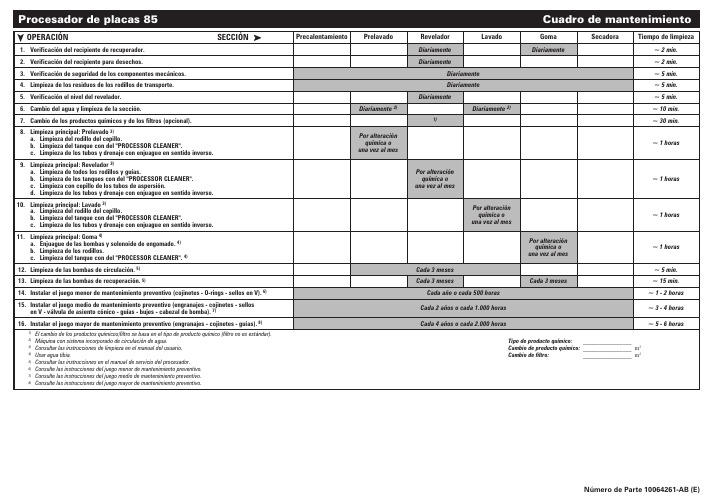
Diariamente 2)
Cuadro de mantenimiento
Goma Diariamente
Secadora
Tiempo de limpieza ~ 2 min. ~ 2 min. ~ 5 min. ~ 5 min. ~ 5 min. ~ 10 min. ~ 30 min.
~ 1 horas
10. Limpieza principal: Lavado 3) a. Limpieza del rodillo del cepillo. b. Limpieza del tanque con del "PROCESSOR CLEANER". c. Limpieza de los tubos y drenaje con enjuague en sentido inverso.
8. Limpieza principal: Prelavado 3) a. Limpieza del rodillo del cepillo. b. Limpieza del tanque con del "PROCESSOR CLEANER". c. Limpieza de los tubos y drenaje con enjuague en sentido inverso.
Procesador de placas 85
OPERACIÓN
SECCIÓN
1. Verificación del recipiente de recuperador.
2. Verificación del recipiente para desechos.
3. Verificación de seguridad de los componentes mecánicos.
sonyCD随身听全解

1984年爱迪生发明电声技术之后的100多年里,唱片技术每隔25年就有一次大的技术革新。
从圆筒方式进入圆盘唱片,到电气式唱盘的登场,再进入LP唱片,再从单音进入立体声。
在第100年里,数字音频技术产生了。
1982年8月31日傍晚,日本各大媒体都争相报导“引发音频之梦的数字Player终于上市”、“数字音频时代开幕”等消息。
原来,当天SONY、CBS/SONY、荷兰飞利浦与POLYGRAM四家公司共同举办了CD这个数字录音格式的发布会,并决定从秋季起开始在日本发售。
直径仅仅12cm,利用数字信号录音,只要一个按钮就可执行选曲,能够半永久的使用,CD实现了许多乐迷的梦想。
是年10月1日,SONY推出了第一台CD机CDP-101。
168,000日圆的价格,对一般消费者而言是很难接受的。
不过只要想到里面的技术与开发时间,能做成商品的确是一个奇迹。
进入1983年后,其它公司的CD机也相继上市,销售形势一片大好。
但是,接下来的一年里CD市场却陷于停滞状态。
原来,当时购买CD系统的人是以Hi-Fi发烧友为主,大部分的人依旧偏好已融入生活的LP。
为了拯救这种颓势,SONY公司通用音响事业部的大曾根幸三,拿了一个边长13.4cm 的四方型、约4张CD盒厚度的木盒对属下说:“接下来就尝试做这种CD Player吧。
”每个人听到大曾根的目标后,都不禁的怀疑自己的耳朵是不是听错了,不过他的做事风格就是如此,因此没有人感觉到这是一个艰难的任务。
对于SONY的产品开发人员来说,这个木盒就代表着使用者的需求,就象他们自己说的,“将技术汇总起来后,不知道可不可以做成这种尺寸?看来是不行的。
不过只有这个尺寸,才是能让每个人都欣喜的产品”。
为了让CD达到普及化阶段,SONY公司订定出了这样的方针:“价格不可超过5万日圆,最初虽然会出现赤字,不过日后一定会赚钱的。
”这样的价格是CDP-101那168,000日圆的1/3左右。
实际上,5万日圆的价格,赤字率高达200%。
- 1、下载文档前请自行甄别文档内容的完整性,平台不提供额外的编辑、内容补充、找答案等附加服务。
- 2、"仅部分预览"的文档,不可在线预览部分如存在完整性等问题,可反馈申请退款(可完整预览的文档不适用该条件!)。
- 3、如文档侵犯您的权益,请联系客服反馈,我们会尽快为您处理(人工客服工作时间:9:00-18:30)。
Model Name Using Similar Mechanism D-E880/EJ815CD Mechanism T ype CDM-3022EBA Optical Pick-up NameDAX-22ESERVICE MANUALE Model Chinese ModelD-VJ85PORTABLE VIDEO CD PLAYERSystemCompact disc digital audio/video system Laser diode propertiesMaterial: GaAlAsWavelength: λ = 780 nmEmission duration: ContinuousLaser output: Less than 44.6 µW (This output is the value measured at a distance of 200 mm from the objective lens surface on the optical pick-up block with 7 mm aperture.)Error correctionSony Super Strategy Cross Interleave Reed Solomon Code D-A conversion1-bit quartz time-axis control Channel number2 channelsFrequency response20 - 20,000 Hz +1/–2 dB (measured by EIAJ CP-307)Output (at 4.5 V input level)Audio output (stereo minijack)Output level 0.7 V rms at 47 kilohms Recommended load impedance over 10kilohmsVideo output (minijack)Output level 1 Vp-p at 75 ohmsRecommended load impedance 75 ohms Headphones (stereo minijack)Approx. 5 mW + Approx. 5 mW at 16 ohmsSPECIFICATIONSPower requirementsFor the area code of the model you purchased, check the upper left side of the bar code on the package.•Two LR6 (size AA) batteries: 3 V DC •AC power adaptor (DC IN 4.5 V jack):E model: 220 - 230 V , 50/60 Hz CH model: 220 V , 50 Hz HK model: 220 V , 50/60 Hz•Two Sony NH-WM2AA rechargeable batteries: 2.4 V DC•Two Sony NC-WMAA rechargeable batteries: 2.4 V DC•Sony DCC-E245 car battery cord for use on car battery: 4.5 V DCBattery life * (approx. hours)(When you use the VIDEO CD player on a flat and stable surface.)Playing time varies depending on how the CD player is used.VIDEO CD Audio CD Two NC-WMAA 110(charged forabout 4 hours **)NH-WM2AA 320(charged forabout 4 hours **)Two Sony alkaline 335batteries LR6SG *Measured value by the standard of EIAJ (Electronic Industries Association of Japan).**Charging time varies depending on how the rechargeable battery is used.Operating temperature5°C - 35°C (41°F - 95°F)Dimensions (w/h/d)(excluding projecting parts and controls)Approx. 131.5 × 25.2 × 141.4 mm (5 1/8 × 3/4 × 5 1/8 in.)MassApprox. 239 g (8.4 oz)(excluding rechargeable batteries)Approx. 298 g (10.5 oz)(including rechargeable batteries and a CD)Design and specifications are subject to change without notice.Supplied accessoriesAC power adaptor AC-E455F (1) (E)AC power adaptor AC-E455 (1) (CH, HK)Audio cable (1)Video cable (1)Wireless remote control RMT-DV11 (1)Earphones with remote controlRM-CD12EL (1) + MDR-E805SP (1)Rechargeable batteries NC-WMAA (2)Battery carrying case (1)Carrying case (1)•AbbreviationCH: Chinese model HK: Hong Kong modelVer 1.0 2000. 03CAUTIONUse of controls or adjustments or performance of proce-dures other than those specified herein may result in haz-ardous radiation exposure.Flexible Circuit Board Repairing•Keep the temperature of the soldering iron around 270°C during repairing.•Do not touch the soldering iron on the same conductor of the circuit board (within 3 times).•Be careful not to apply force on the conductor when soldering or unsoldering.Notes on Chip Component Replacement •Never reuse a disconnected chip component.•Notice that the minus side of a tantalum capacitor may be damaged by heat.This Compact Disc player is classified as a CLASS 1LASER product.The CLASS 1 LASERPRODUCT table is located on the bottom exterior.SAFETY-RELATED COMPONENT WARNING!!COMPONENTS IDENTIFIED BY MARK 0 OR DOTTED LINE WITH MARK 0 ON THE SCHEMATIC DIAGRAMS AND IN THE PARTS LIST ARE CRITICAL TO SAFE OPERATION.REPLACE THESE COMPONENTS WITH SONY PARTS WHOSE PART NUMBERS APPEAR AS SHOWN IN THIS MANUAL OR IN SUPPLEMENTS PUBLISHED BY SONY.NOTES ON HANDLING THE OPTICAL PICK-UP BLOCK OR BASE UNITThe laser diode in the optical pick-up block may suffer electro-static breakdown because of the potential difference generated by the charged electrostatic load, etc. on clothing and the human body.During repair, pay attention to electrostatic breakdown and also use the procedure in the printed matter which is included in the repair parts.The flexible board is easily damaged and should be handled with care.Precautions for Checking Emission of Laser DiodeLaser light of the equipment is focused by the object lens in the optical pick-up so that the light focuses on the reflection surface of the disc. Therefore, be sure to keep your eyes more then 30 cm apart from the object lens when you check the emission of laser diode.Before Replacing the Optical Pick-Up BlockPlease be sure to check throughly the parameters as par the “Opti-cal Pick-Up Block Checking Procedures” (Part No.: 9-960-027-11) issued separately before replacing the optical pick-up block.Note and specifications required to check are given below.•FOK output : IC601 eg pinWhen checking FOK, remove the lead wire to disc motor.•RF signal P-to-P value : 0.35 - 0.65 Vp-pLaser Diode Checking MethodsDuring normal operation of the equipment, emission of the laser diode is prohibited unless the upper lid is closed while turning ON the S801. (push switch type)The following two checking methods for the laser diode are operable.•Method:Emission of the laser diode is visually checked.1.Open the upper lid.2.With a disc not set, turn on the S801 with a screwdriver having a thin tip as shown in Fig.1.or TAP802 is shorted as shown in Fig.2.Note:Do not push the detection lever strongly, or it may be bentor damaged.3.Press the u button.4.Observing the objective lens, check that the laser diode emits light.When the laser diode does not emit light, automatic power control circuit or optical pickup is faulty.In this operation, the objective lens will move up and down 5times along with inward motion for the focus search.Fig. 1TABLE OF CONTENTS1. GENERALGetting started (4)Playing a VIDEO CD (4)Playing an audio CD (5)2. DISASSEMBLY2-1. Cabinet (Lower) Assy (6)2-2. Lid Assy, Upper (6)2-3. Switch Board (7)2-4. MD Assy (7)2-5. Main Board, IR Board (8)2-6. Optical Pick-up (8)3. TEST MODE3-1. How to Enter the Test Mode (9)3-2. How to Release the Test Mode (9)3-3. Each Key Function in Test Mode (9)4. ELECTRICAL ADJUSTMENT4-1. Focus Bias Check (11)5. DIAGRAMS5-1. IC Pin Descriptions (12)5-2. Block Diagram –CD Section (1/2)– (17)5-3. Block Diagram –CD Section (2/2)– (19)5-4. Block Diagram –Video Section– (21)5-5. Block Diagram –Power Supply Section– (23)5-6. Printed Wiring Boards (25)5-7. Schematic Diagram –Main Section (1/4)– (29)5-8. Schematic Diagram –Main Section (2/4)– (31)5-9. Schematic Diagram –Main Section (3/4)– (33)5-10. Schematic Diagram –Main Section (4/4)– (35)6. EXPLODED VIEWS6-1. Cabinet Section (41)6-2. CD Mechanism Deck Section (42)7. ELECTRICAL PARTS LIST (43)SECTION 1GENERALThis section is extracted from instruction manual.Locating the ControlsFor details, see pages in parentheses.CD player (front)Getting startedRemote controlNoteUse only the supplied remote control. You cannot operate this VIDEO CD player with the remote control supplied with other VIDEO CD players.(Front)(Rear)clip.CD player (rear)Wireless remote controlmodel.21, 22, 23)(Continued)Playing a VIDEO CDYou can play back a VIDEO CD, using the supplied AC power adaptor. You can also use rechargeable batteries and alkaline batteries. (See “Connecting a power source ” on pages 28 –30.)To produce color pictures normally, you need to set the color system properly according to theDo this Press u .Press x /CHG (x ).Press uPress > repeatedly until you find the scene or track.Press . repeatedly unitl you find the scene or track.Press the number button of the track (wireless remote control only).Press . or > and hold it down until m or M appears on the TV screen.To Pause StopResume play after pauseLocate the next or succeeding tracks Locate the current or preceding tracks Locate a specific track directlyLocate a point in the track while monitoring the picture**To return to normal playback, press u .The above operations can also be done with the buttons on the supplied earphones with remote control or wireless remote control.About the display•No indication appears on the display while you operate the unit with the wired remote control.•During play, the track number and the elapsed playing time of the current track appear.•During pause, the elapsed playing time flashes.If the volume level does not increase (when listening with the headphones/earphone)Is A VLS set to “LIMIT ”? Set A VLS to “NORM.” For details, see “To protect your hearing (A VLS)” on page 24.If a cable is connected to the AUDIO OUT jack, you cannot adjust the volume. In such a case,disconnect the cable.Removing the VIDEO CDPlaying an audio CDYou can also use rechargeable batteries, alkaline batteries and a car battery. (See “Connecting aheard.Press ux /CHG (x )u. once**. repeatedly**> once**> repeatedly**Number buttons of the track (wireless remote control only)**Hold down >**Hold down .**To Pause StopResume play after pauseFind the beginning of the current track (AMS*)Find the beginning of previous tracks (AMS)Find the beginning of the next track (AMS)Find the beginning of succeeding tracks (AMS)Locate a specific track directly Go forward quickly Go backwards quickly *Automatic Music Sensor**These operations are possible during both play and pause.The above operations can also be done with the buttons on the supplied earphones with remote control or wireless remote control.If you press REPEAT/ENTER (RPT/ENT) to display “REPEAT ”, you can locate the tracks continuously in the following order:•When using >: next track t next track ...... last track t first track t second track ......•When using .: previous track t previous track ...... first track t last track ......About the display•When playing an audio CD using the AC power adaptor, indications on the remote controldisplay window go off until the sound is heard.•When you press u , the total number of tracks in the audio CD and total playing time appear for about two seconds.•During play, the track number and the elapsed playing time of the current track appear.•Between tracks, the time to the beginning of the next track appears with the “-” indication.•During pause, the elapsed playing time flashes.If the volume level does not increaseIs A VLS set to “LIMIT ”? Set A VLS to “NORM.” For details, see “To protect your hearing (A VLS)” on page 24.If a cable is connected to the AUDIO OUT jack, you cannot adjust the volume. In such a case,disconnect the cable.Removing the audio CD3 boss2 boss1 screw (M1.4), step4 lid assy, upperlid, battery caseclaws7 claws6 claw4 claws8 CN8013 claws5 claws2 screws (B2)1 screws (B2)9cabinet (lower) assy • The equipment can be removed using the following procedure.2-2. LID ASSY, UPPERSECTION 2DISASSEMBL YNote : Follow the disassembly procedure in the numerical order given.2-1. CABINET (LOWER) ASSYSetCabinet (Lower) AssyLid Assy, Upper Switch BoardMain Board, IR Board Optical Pick-up4SWITCH board2-3. SWITCH BOARD 2-4. MD ASSY36 optical pick-up2 rack1 M1.4x1.83 M1.4x45 shaft, standard4 bracket assy, sled2-5. MAIN BOARD, IR BOARD2-6. OPTICAL PICK-UPSECTION 3TEST MODE3-1. OUTLINEThis set has the test mode in which the pick-up can be operational checked and the video signal can be verified.3-2. PICK-UP OPERATIONAL CHECKS3-2-1. Setting the test mode 1.Switch positionsOPEN switch (S801): OPEN HOLD switch (S804): OFF A VLS switch (S893): OFF2.Short the TEST terminal TAP801 (TEST) by soldering it.Remove the solder from the TAP901 (V-TEST) and open the terminal.3.Supply4.5 V DC from the DC jack (J401).3-2-2. Releasing the test mode1.Open the TEST terminal TAP801 (TEST) and short the TAP901 (V-TEST).2.Turn the power OFF.3-2-3.Operational checks1.When a specific key is operated:KEYContents of the operation.((LCD DISPLAY))u Spindle on. Tracking servo off.((UP 00 03))x All servo off. Mute on.CHG ((10 different displays are repeatedly presented.))Moves the pick-up to the outside (with the open >switch open). Tracking servo off. Mute on.NEXT((Among 10 different displays, the display when the key is pressed is held.))Moves the pick-up to the inside (with the open.switch open). Tracking servo off. Mute on.PREV((Among 10 different displays, the display when the key is pressed is held.))2.In play mode • Press the u key:KEYContents of the operation.((LCD DISPLAY))Tracking servo on. Mute off.Each time this key is pressed, the display changes PLAY as follows:MODEx1 speed t x2 speed t x3 speed t x4 speed t x1 speed(( 01 00 01)) t ((02 00 02)) t ((03 00 03))t ((04 00 04))Each time this key is pressed, the display changes SELECT as follows:REPEAT/Tracking gain up. Emphasis on. LCD back light ENTERon h Tracking gain down. Emphasis off.LCD back light off3-3. VIDEO SIGNAL VERIFICATION3-3-1. Setting the test mode 1.Switch positionsOPEN switch (S801): OPEN HOLD switch (S804): OFF A VLS switch (S893): OFF2.Short the TEST terminal TAP801(TEST) by soldering it.Remove the solder from the TAP901(V-TEST) and connect the terminal to the TP945 (VDD) with a 47 k Ω resistor.3.Supply 4.5V DC from the DC jack (J401).3-3-2. Releasing the test mode1.Open the TEST terminal TAP801(TEST). Remove the resistor from the TAP901 (V-TEST) and short the terminal by soldering it.2.Turn the power OFF.3-3-3. Operational checks1.Connect the TP931 to the TP945 (VDD) with a 47 k Ω resistor (NTSC mode).2.Press the O RETURN key once.3.Verify that a 100% white pattern is output from the VIDEO OUT (J901).4.Press the O RETURN key once (output off).5.Connect the TP931 to the TP919 (GND) (PAL mode).6.Press O RETURN key once.7.Verify that a 100% white pattern is output from the VIDEO OUT (J901).8.Press the O RETURN key once (output off).9.Open the TP931.Fig. 100% white patternAdjustment Location: See page 10.Test Points:– main board (side A) –– main board (side B) –1. 2. 3. 4.5.•SECTION 4 ELECTRICAL ADJUSTMENTCD section adjustments are done automatically in this set.1.2.3.A•Test Points:– 11 –SECTION 5DIAGRAMS5-1. IC PIN DESCRIPTIONS• IC801 TMP88CM22F (SYSTEM CONTROLLER)Pin No.Pin Name I/O Pin Description1VSS I Ground2IRRMC I Infrared remote control signal input3FOKI I Focus OK signal input from CXD3027R (IC601).4AGCCON O AGC control pulse output5XLEDDISP O CHG/HOLD LED control signal output6VCC SWITCHING O Control signal output for Switching power supply circuit.7AMUTE O Analog audio muting ON/OFF signal control signal output (H: Mute ON)8VCC2 ON O VCC2 voltage control output9XRST O Reset signal output to CXD3027R (IC601). (L: Reset)10SCK O Serial data transfer clock signal output to CXD3027R (IC601).11SDTI I Serial data input from CXD3027R (IC601).12SDTO O Serial data output to CXD3027R (IC601).13SLPOUT O WAKE-UP control signal output (for system standby reset)14SEL I Plug-in detection signal input of AUDIO OUT (OPTICAL) jack.15CHGMNT1I Battery charge voltage detection input from TB2119F (IC401).16VCDKEY I VCD key input17BATMNT I Battery voltage detection input18KEY I Key input from switch board (A/D input).19RMKEY I Key input from headphones with remote controller (A/D input).20DCINMNT I DC input voltage detection input (A/D input) DC input jack use/no-use detect input 21OPEN I CD door open/close detection input22VREFL I Reference voltage (0 V) input for A/D converter.23VREFH I Reference voltage (+2 V) input for A/D converter.24VDD—Power supply pin (+2 V)25SCOR I Sub code sync detection input from CXD3027R (IC601).26GRSCOR I GRSCOR signal input27FG I FG pulse input28BEEP O Beep sound output to headphone AMP (IC351).29XU TX REQ O Request signal output to TMP87PM41U (IC902).30RMSCK O Communication clock to CXD751-103R (IC802) and TMP87PM41U (IC902).31RMDATI I Communication data bus input from CXD751-103R (IC802) and TMP87PM41U (IC902).32RMDA TO O Communication data bus output to CXD751-103R (IC802) and TMP87PM41U (IC902).33RMRW O Read/write control signal output to headphones with remote. (L: Read, H: Write) 34RMLAT O Serial data latch pulse output to headphones with remote.35WFCKI I WFCK input36NC—Not used. (Open)37XNTSC I I NTSC/PAL select input (“L”: PAL, “H”: NTSC)38A VLS I A VLS (Automatic V olume Limiter System) switch input (L: Normal, H: Limit) 39HOLD I HOLD switch input (L: HOLD on, H: HOLD off)40EX BATT I EXT BATT plug-in detection input41XSPDOE O Spindle motor driver control signal output42XHGON O Optical pick-up VCC control signal output (L: on)43XLAT O Serial data latch pulse output to CXD3027R (IC601). (for ESP)44XSOE O Output enable signal output (for ESP)45DRVLT O Spindle motor driver latch output46XPOWLT O Latch output to VCD control IC.47XDOUTON O DIGITAL OUT LED control signal output48XAPC OFF O APC mute signal output (L: mute)49XVRST O Reset signal output to TMP87PM41U (IC902).50 – 52SEG14 – 12O LCD drive segment output53 – 56SEG11 – 8O LCD drive segment output– 12 –Pin No.Pin Name I/O Pin Description57 – 64SEG7 – 0O LCD drive segment output65 – 68COM3 – 0O LCD drive common output69 – 71V3 – 1O LCD drive bias output72, 73C1, 0O Capacitor connected terminal of LCD driver for voltage-up.74STOP O Stop signal output to VCD control IC.75TEST I Test terminal for IC. (Fixed at L in this set)76XHPSW O Headphone AMP ON/OFF control signal output (L: ON) 77XLIGHT O LCD back light control signal output to LCD.78RESET I System reset signal input from TB2119F (IC401). (L: Reset) 79XIN I Oscillation input80XOUT O Oscillation output (Open)– 13 –• IC902 TMP87PM41U (MICON VIDEO ENCODER/VIDEO CONTROLLER)Pin No.Pin Name I/O Pin Description1 – 8P00 – 07—Not used. (Open)9(INT0) P10—Not used. (Open)10(INT1) P11—Not used. (Open)11(INT2/TC1) P12—Not used. (Open)12(DVO) P13—Not used. (Open)13(PPG) P14—Not used. (Open)14(TC2) P15—Not used. (Open)15P16—Not used. (Open)16P17I Visual system test mode pin (“L”: Test mode)17P20 (INT5/STOP)I Interruption request signal input from CL680T-D1 (IC906).18TEST I Test pin (Fixed at “L” in this set)19P21 (XTI)—Not used. (Open)20P22 (XTOUT)—Not used. (Open)21RESET I I System reset signal input from TMP88CM22F (IC801). (“L”: Reset) 22XIN I I High frequency oscillator input from TMP88CM22F (IC801).23XOUT O High frequency oscillator output (Not used in this set)24VSS—Digital ground25P30O CD DA/CD ROM judgment output (“L”: Audio CD)26 – 30P31 – 35—Not used. (Open)31——Not used. (Open)32 C RESET O Reset signal output to CL680T-D1 (IC906). (“L”: Reset)33P40O Ready signal output to CL680T-D1 (IC906).34P41O Address select signal output to CL680T-D1 (IC906).35P42 (SCK1)O Serial clock signal output to CL680T-D1 (IC906).36P43 (SI1)I Serial data signal input from CL680T-D1 (IC906).37P44 (SO1)O Serial data signal output to CL680T-D1 (IC906).38P45 (SCK2)I Serial clock signal input from TMP88CM22F (IC801).39P46 (SI2)I Serial data signal input from TMP88CM22F (IC801).40P47 (SO2)O Serial data signal output to TMP88CM22F (IC801).41P50 (INT3/TC3)I Request signal input from TMP88CM22F (IC801).42P51 (INT4/TC4)I Ready signal input from TMP88CM22F (IC801).43P52 (PWM/PDO)O Request signal output to TMP88CM22F (IC801).44P53 (HPWM0)—Not used. (Open)45P54 (HPWM1)—Not used. (Open)46A VSS—Not used. (Open)47A VREF—Not used. (Open)48(AIN0) P60—Not used. (Open)49(AIN1) P61—Not used. (Open)50(AIN2) P62—Not used. (Open)51(AIN3) P63—Not used. (Open)52(AIN4) P64—Not used. (Open)53(AIN5) P65—Not used. (Open)54(AIN6) P66—Not used. (Open)55(AIN7) P67—Not used. (Open)56VDD—Digital power supply pin (+3.2 V)57(AIN10) P70—Not used. (Open)58(AIN11) P71—Not used. (Open)59(AIN12) P72—Not used. (Open)60(AIN13) P73—Not used. (Open)61(AIN14) P74—Not used. (Open)62(AIN15) P75—Not used. (Open)63(AIN16) P76—Not used. (Open)64(AIN17) P77—Not used. (Open)– 14 –– 39 –IC601 CXD3027RA9A8A7DVSS V D D C O U M I R D F C F O P W M L O C H P H P H P V D D C 17M D M D S S T S F D S R D T F D T R D F F D F R D V S S T E S T E S A V D D I G E A V S S R F D O E C A S 2301W E R A S 1110V D D 0123V D D 2O U T 2I N 2O U T 2V S S 2V S S 1O U T 1I N 1O U T 1V D D 1V S S T A O T A I V D D C K IA6A5A4XWRE XRDE XEMP XWIH XQOK AMUTE SDTI XQCK SCSY SCOR VSS0SBSO EXCK XRST SYSM SDTO XLAT CLOK SENS SCLK XSOE ATSK R4MBCK PCMDI PCMD LRCKI LRCK DOUT VDD2WFCK C2PO GFS XPCK XUGF WDCK VSS2XTSL AVDD3ASYO ASYI BIAS RFAC AVSS3CLTV PCO FILI FILO VCTL VPCO VC A B– 40 –IC351 TA2120FNBEEP NFOUTSWGNDOUTINDETATT MT MT PW BIASBST BST IC802 CXD751-103RIC803 TC7W53FU (TE12R)O 26O 27C C S S 2S B W S E L 2S E L 2V S S X L T S O S C K R E S E L 2L T– 41 –SECTION 6EXPLODED VIEWSRef. No.Part No.DescriptionRemark6-1. CABINET SECTIONRef. No.Part No.DescriptionRemarkNOTE:•The mechanical parts with no referencenumber in the exploded views are not supplied.•Accessories and packing materials are given in the last of this parts list.•Items marked “*” are not stocked sincethey are seldom required for routine service.Some delay should be anticipated when ordering these items.The components identified by mark 0 or dotted line with mark 0 are critical for safety.Replace only with part number specified.1X-4952-439-1CABINET (LOWER) SUB ASSY 24-225-414-01LID, BATTERY CASE 34-908-792-91SCREW (B2)44-224-048-01FOOT, RUBBER54-225-413-01WINDOW (RAY CATCHER)64-224-020-01KNOB (HOLD)*71-676-499-11IR BOARD8A-3323-414-A MAIN BOARD, COMPLETE94-225-416-01TERMINAL SPRING (–), BATTERY 104-225-417-01PLATE, CHARGE DETECTION 114-225-415-01TERMINAL BOARD (+), BATTERY 124-908-792-51SCREW (B2)133-318-382-01SCREW (1.7X3), TAPPING 144-225-407-01LEVER, DETECTION 154-224-229-01SPACER (A)16X-4952-438-1OPEN ASSY 174-224-016-01KNOB (OPEN)184-224-015-01BUTTON (VOL)19X-4952-437-1CABINET (UPPER) SUB ASSY 20X-4952-436-1PLATE ASSY, ORNAMENTAL 213-345-710-21SCREW (M1.4X3) TAPPING 22X-4952-435-1LID SUB ASSY, UPPER 234-224-230-01SPACER (B)243-043-558-01SPRING (B) (OPEN)25X-4952-205-1ARM ASSY, SWITCHING *261-674-587-21SWITCH BOARD274-224-053-01SCREW (M1.4), STEP 284-221-927-01INSULATOR293-375-114-51SCREW303-042-766-11CUSHION (BATT)313-318-201-51SCREW (B) (1.4X4), TAPPING 323-318-382-01SCREW (1.7X3), TAPPING 333-045-650-01SHEET, RADIATION343-044-559-01RAIL354-225-396-01SPACER (C)*361-678-339-11WAKE BOARD– 42 –51525354555657575859606162636465M902M9016-2. CD MECHANISM DECK SECTION(CDM-3022EBA)Ref. No.Part No.DescriptionRemark Ref. No.Part No.DescriptionRemark51A-3328-418-A CHASSIS ASSY (INCLUDING M902)524-220-645-01SHAFT, STANDARD 053X-4952-079-1DAX-22E RP ASSY 544-220-646-01RACK553-704-197-92SCREW (M1.4X1.8), LOCKING56X-4951-687-1BASE ASSY, SLED573-348-998-61SCREW (M1.4X4), TAPPING, PAN584-220-648-01GEAR (C)593-338-645-31WASHER (0.8-2.5)60A-3328-298-A SCREW ASSY, FEED61A-3328-299-AMOTOR BLOCK ASSY , SLED(INCLUDING M901)624-964-564-01SCREW (M1.2X1.6)633-686-458-03SCREW (P1.4X3.5), TAPPING 644-973-631-31SCREW65X-4951-688-1BRACKET ASSY , SLEDThe components identified by mark 0 or dotted line with mark 0 are critical for safety.Replace only with part number specified.– 43 –SECTION 7ELECTRICAL PARTS LISTRef. No.Part No.Description Remark Ref. No.Part No.Description Remark NOTE:•Due to standardization, replacements in the parts list may be different from the parts specified in the diagrams or the components used on the set.•RESISTORSAll resistors are in ohms.METAL:Metal-film resistor.METAL OXIDE: Metal oxide-film resistor.F:nonflammable •Items marked “*” are not stocked sincethey are seldom required for routine service.Some delay should be anticipated when ordering these items.•SEMICONDUCTORSIn each case, u : µ, for example:uA..: µA..uPA..: µPA..uPB..: µPB..uPC..: µPC.. uPD.. : µPD..•CAPACITORS uF : µF •COILS uH : µHThe components identified by mark 0 or dotted line with mark 0 are critical for safety.Replace only with part number specified.When indicating parts by reference number, please include the board.MAIN•AbbreviationCH : Chinese model HK : Hong Kong modelIR*1-676-499-11IR BOARD*********< IC >PH9018-749-015-96IC GP1UC10J*************************************************************A-3323-414-A MAIN BOARD, COMPLETE*********************< CAPACITOR >C1011-104-851-11TANTAL. CHIP 10uF 20%10V C1021-162-925-11CERAMIC CHIP 68PF 5%50V C1031-164-230-11CERAMIC CHIP 220PF 5%50V C1041-126-246-11ELECT CHIP 220uF 20%4V C1611-107-826-11CERAMIC CHIP 0.1uF 10%16V C1631-125-838-11CERAMIC CHIP 2.2uF 10% 6.3V C2011-104-851-11TANTAL. CHIP 10uF 20%10V C2021-162-925-11CERAMIC CHIP 68PF 5%50V C2031-164-230-11CERAMIC CHIP 220PF 5%50V C2041-126-246-11ELECT CHIP 220uF 20%4V C2611-107-826-11CERAMIC CHIP 0.1uF 10%16V C2631-125-838-11CERAMIC CHIP 2.2uF 10%6.3V C3011-117-720-11CERAMIC CHIP 4.7uF 10V C3041-164-156-11CERAMIC CHIP 0.1uF 25V C3061-115-156-11CERAMIC CHIP 1uF 10V C3071-127-569-11TANTAL. CHIP 100uF 20%4V C3081-164-156-11CERAMIC CHIP 0.1uF 25V C3611-135-259-11TANTAL. CHIP 10uF 20% 6.3V C3621-115-156-11CERAMIC CHIP 1uF 10V C3631-125-837-11CERAMIC CHIP 1uF 10%6.3V C3641-115-156-11CERAMIC CHIP 1uF 10V C3651-135-259-11TANTAL. CHIP 10uF 20% 6.3V C4011-164-156-11CERAMIC CHIP 0.1uF 25V C4031-162-964-11CERAMIC CHIP 0.001uF 10%50V C4041-104-752-11TANTAL. CHIP 33uF 20% 6.3V C4051-104-752-11TANTAL. CHIP 33uF 20% 6.3V C4061-164-156-11CERAMIC CHIP 0.1uF 25V C4071-162-970-11CERAMIC CHIP 0.01uF 10%25V C4081-109-982-11CERAMIC CHIP 1uF 10%10V C4111-109-982-11CERAMIC CHIP 1uF 10%10V C4121-162-970-11CERAMIC CHIP 0.01uF 10%25V C4131-162-925-11CERAMIC CHIP 68PF 5%50V C4141-125-899-11TANTAL. CHIP 220uF 20%4V C4151-110-569-11TANTAL. CHIP47uF20%4VC4161-115-156-11CERAMIC CHIP 1uF 10V C4171-104-852-11TANTAL. CHIP 22uF 20%10V C4181-164-156-11CERAMIC CHIP 0.1uF 25V C4191-104-847-11TANTAL. CHIP 22uF 20%4V C4201-115-156-11CERAMIC CHIP 1uF 10V C4211-164-677-11CERAMIC CHIP 0.033uF 10%16V C4221-162-927-11CERAMIC CHIP 100PF 5%50V C4231-162-970-11CERAMIC CHIP 0.01uF 10%25V C4241-110-569-11TANTAL. CHIP 47uF 20%6.3V C4251-164-156-11CERAMIC CHIP 0.1uF 25V C4261-104-851-11TANTAL. CHIP 10uF 20%10V C4271-115-156-11CERAMIC CHIP 1uF 10%10V C4281-164-156-11CERAMIC CHIP 0.1uF 25V C4301-135-201-11TANTALUM CHIP 10uF 20%4V C4311-110-569-11TANTAL. CHIP 47uF 20%4V C4321-113-682-11TANTAL. CHIP 33uF 20%10V C4331-164-156-11CERAMIC CHIP 0.1uF 25V C4341-162-970-11CERAMIC CHIP 0.01uF 10%25V C4351-125-838-11CERAMIC CHIP 2.2uF 10% 6.3V C4361-110-501-11CERAMIC CHIP 0.33uF 10%16V C4371-109-982-11CERAMIC CHIP 1uF 10%10V C4381-115-156-11CERAMIC CHIP 1uF 10V C4391-110-569-11TANTAL. CHIP 47uF 20%4V C4411-162-970-11CERAMIC CHIP 0.01uF 10%25V C4421-162-970-11CERAMIC CHIP 0.01uF 10%25V C4441-115-467-11CERAMIC CHIP 0.22uF 10%10V C4451-104-913-11TANTAL. CHIP 10uF 20%16V C4461-164-156-11CERAMIC CHIP 0.1uF 25V C4471-109-982-11CERAMIC CHIP 1uF 10%10V C4481-162-925-11CERAMIC CHIP 68PF 5%50V C4491-115-566-11CERAMIC CHIP 4.7uF 10%10V C4501-125-838-11CERAMIC CHIP 2.2uF 10% 6.3V C4511-162-964-11CERAMIC CHIP 0.001uF 10%50V C4521-162-964-11CERAMIC CHIP 0.001uF 10%50V C4531-162-964-11CERAMIC CHIP 0.001uF 10%50V C4541-162-969-11CERAMIC CHIP 0.0068uF 10%25V C4561-115-156-11CERAMIC CHIP 1uF 10%10V C4571-162-964-11CERAMIC CHIP 0.001uF 10%50V C4591-110-569-11TANTAL. CHIP 47uF 20% 6.3V C4611-162-962-11CERAMIC CHIP 470PF10%50V C4621-162-968-11CERAMIC CHIP 0.0047uF 10%50V C4631-107-826-11CERAMIC CHIP 0.1uF 10%16V C5011-164-156-11CERAMIC CHIP 0.1uF 25V C5021-104-847-11TANTAL. CHIP 22uF 20%4V C6011-164-156-11CERAMIC CHIP0.1uF25V。