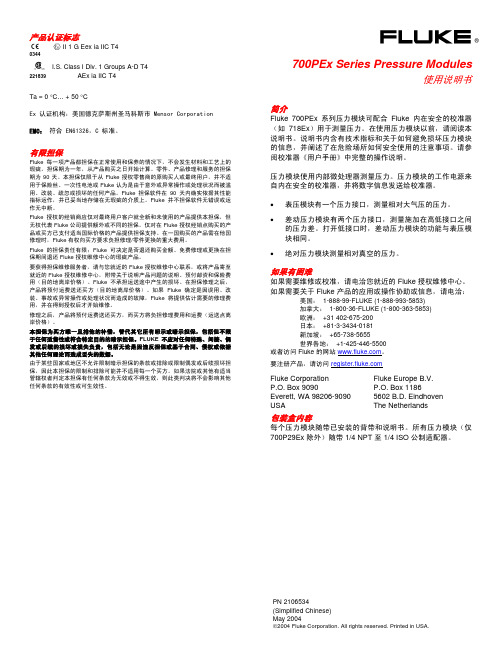
Fluke718压力校准器使用手册
Fluke 718Ex_用户手册中文版(校准器)

718Ex 30G/100G/300G Pressure Calibrator
May 2004 Rev. 2, 5/09 (Simplified Chinese)
© 2004-2009 Fluke Corporation. All rights reserved. Specifications are subject to change without notice. All product names are trademarks of their respective companies.
Fluke Corporation
Fluke Europe B.V.
P.O. Box 9090
P.O. Box 1186
Everett, WA 98206-9090
5602 BD Eindhoven
U.S.A.
The Netherlands
要上网注册您的产品,请访问 。
Fluke 仅授权经销商将本保证提供给购买新的、未曾使用过的产品的最终用户。经销商无权以 Fluke 的名义来给予其它任何担保。保修服务仅 限于从 Fluke 授权销售处所购买的产品,或购买者已付出适当的 Fluke 国际价格。在某一国家购买而需要在另一国家维修的产品,Fluke 保留 向购买者征收维修/更换零件进口费用的权利。 Fluke 的保证是有限的,在保修期间退回 Fluke 授权服务中心的损坏产品,Fluke 有权决定采用退款、免费修理或更换产品的方式处理。 欲取得保证服务,请和您附近的 Fluke 服务中心联系,或把产品寄到最靠近您的 Fluke 服务中心(请说明故障所在,预付运费和保险费用,并 以 FOB 目的地方式寄送)。Fluke 不负责产品在运输中的损坏。保修期修理以后,Fluke 会将产品寄回给购买者(预付运费,并以 FOB 目的 地方式寄送)。若 Fluke 判断故障是由于疏忽、误用、污染、修改、意外或非正常的工作条件或处理方式(包括使用产品指标以外的过电压故 障或机械部件的一般磨损)而产生,Fluke 会对维修费用作出估价,并取得购买者的同意以后才进行维修。维修后,Fluke 将把产品寄回给购 买者(预付运费,FOB 运输点),同时向购买者征收维修和运输的费用。 本项保证是购买者唯一及专有的补偿,并且它代替了所有其它明示或默示的保证,包括但不限于保证某一特殊目的适应性的默示保证。凡因任 何原因所引起的特别、间接、附带或继起的损坏或损失(包括数据的损失),FLUKE 也一概不予负责。 由于某些国家或洲不允许对默示保证及附带或继起的损坏有所限制,本保证的限制及范围或许不会与每位购买者有关。若本保证的任何条款被 具有合法管辖权的法庭裁定为不适用或不可强制执行,该项裁定将不会影响其它条款的有效性或强制性。
fluke使用说明书
fluke使用说明书福禄克flukedtx系列(dtx-1800,dtx-1200,dtx-lt)简单操作步骤说明:一、福禄克测试仪初始化步骤:1、充电:产品主机、辅机分别用电源适配器充电,直至电池显示灯转为绿色;2、设置语言:操作方式:将flukedtx系列产品主机旋钮转回至“setup”档位,按右下角绿色按钮开机;采用↓箭头;选上第三条“instrumentsetting”(本机设置)按“enter”步入参数设置,首先采用→箭头,按一下;步入第二个页面,↓箭头挑选最后一项language按“enter”步入;↓箭头挑选最后一项chinese按“enter”挑选。
将语言选择成中文后才展开以下操作方式。
3、自校准:取flukedtx系列产品cat6a/classea永久链路适配器,装在主机上,辅机装上cat6a/classea通道适配器。
然后将永久链路适配器末端插在cat6a/classea通道适配器上;打开辅机电源,辅机自检后,“pass”灯亮后熄灭,显示辅机正常。
“specialfunctions”档位,关上主机电源,表明主机、辅机软件、硬件和测试标准的版本(辅机信息只有当辅机开机并和主机相连接时才表明),自测后表明操作界面,挑选第一项“设置基准”后(例如看错用“exit”选择退出重复),按“enter”键和“test”键已经开始自校准,表明“设置基准已完成”表明自校准顺利顺利完成。
二、设置福禄克测试仪基本参数操作:将flukedtx系列产品主机旋钮转至“setup”档位,使用“↑↓”来选择第三条“仪器值设置”,按“enter”进入参数设置,可以按“←→”翻页,用“↑↓”选择你所需设置的参数,按enter进入参数修改,用“↑↓”选择你所需采用的参数设置,选好后按enter选定并完成参数设置。
1、新机第一次采用须要设置的参数,以后不须要修改。
(将旋钮转回至“setup”档位,采用↓箭头;选上第三条:仪器设置值按enter步入如果回到上一级恳请按exit):1)线缆标识码来源:(一般使用自动递增,会使电缆标识的最后一个字符在每一次保存测试时递增一般不用更改)2)图形数据存储:(就是)(否)通常情况下挑选(就是)3)当前文件夹:default可以按enter进入修改其名称(你想要的名字)4)结果存放位置:(使用默认值“内部存储器”假如有内存卡的话也可以选择“内存卡”)5)按→进入第2个设置页面,操作员:youname按enter进入按f3删除原来的字符“←→↑↓”来选择你要的字符选好后按enter确定11)长度单位:通常情况下挑选米(m)2、新机不须要设置使用原机器默认值的参数:1)电源停用超时:预设30分钟2)背光超时:预设1分钟3)可以听音:预设就是4)电源线频率:默认50hz5)数字格式:预设就是00.06)将旋钮转至“setup”档位选择双绞线按enter进入后nvp不用修改7)光纤里面的设置,在测试双绞线是不须修改3、采用过程中经常须要改动的参数:将旋钮转至“setup”档位,选择双绞线,按enter进入:线缆类型:按enter进入后按↑↓选择你要测试的线缆类型例如我要测试超5类的双绞线在按enter进入后选择utp按enter↑↓选择“cat5eutp”按enter返回。
Fluke 714 热电偶校准器说明书

®714Thermocouple CalibratorInstruction SheetIntroductionThe Fluke 714 Thermocouple Calibrator is a precise source and measurement tool for calibrating thermocouple instruments. The calibrator sources or measures in units of °C, °F, or mV, through a thermocouple minijack.Your calibrator is supplied with a Flex-Stand ™ holster, aninstalled 9 V alkaline battery, and this instruction sheet. Sets of thermocouple miniplugs are available from Fluke. (Accessories Fluke-700TC1 and Fluke-700TC2 TC Miniplug Kits.)If the calibrator is damaged or something is missing, contact the place of purchase immediately. Contact your Fluke distributor for information about accessories. To order replacement parts or spares, see “Replacement Parts.”The following tables list the thermocouple types supported by the calibrator, the standards and scales used for each type, thethermocouple properties, and calibrator resolution. Full calibrator specifications are listed at the end of this instruction sheet.NoteSince mV input and output units are available, you can use the calibrator for any thermocouple type by making manual calculations or referring to tables.PN 650306 July 1997 Rev. 1, 10/97©1997 Fluke Corporation. All rights reserved. Printed in U.S.A.All product names are trademarks of their respective companies.1.888.475.5235*********************Fluke -Direct.comThermocouple Standards and Scales Thermocouple Type Standard Scale J, K, T, E, R, S, B NIST 175ITS-90 L (J-DIN), U (T-DIN)DIN 43710IPTS-68Thermocouple PropertiesThermocoupleType TemperatureRangesDisplay ResolutionJ-200 to 1200°C,-328 to 2192°F0.1°C or °FK-200 to 1370°C-328 to 2498°F0.1°C or °FT-200 to 400°C-328 to 752°F0.1°C or °FE-200 to 950°C-328 to 1742°F0.1°C or °FR-20 to 1750°C-4 to 3182°F1°C or °FS-20 to 1750°C-4 to 3182°F1°C or °FB600 to 1800°C1112 to 3272°F1°C or °FL-200 to 900°C-328 to 1652°F0.1°C or °FU-200 to 600°C-328 to 1112°F0.1°C or °F1.888.475.5235 *********************Millivolt Range and ResolutionMode Range Display ResolutionmV-10 to 75 mV0.01 mVExplanation of International SymbolsThe following symbols are used on the calibrator or in thisinstruction sheet. The table below explains their meaning.International SymbolsSymbol MeaningJ Earth groundI FuseM BatteryW Refer to this instruction sheet for information aboutthis feature.T Double insulatedConforms to relevant Canadian StandardsAssociation directives.P Conforms to European Union directives*********************1.888.475.5235Safety InformationW WarningTo avoid possible electric shock or personal injury:•Never apply more than 30 V between the TCterminals, or between either TC terminal andearth ground.•Make sure the battery door is closed andlatched before you operate the calibrator.•Remove an attached thermocouple miniplugfrom the calibrator before you open the batterydoor.•Do not operate the calibrator if it is damaged.•Do not operate the calibrator around explosivegas, vapor, or dust.When servicing the calibrator, use only specified replacementparts.Turning the Calibrator OnPress the green O pushbutton to turn the calibrator on and off.*********************1.888.475.5235Measuring a Thermocouple*********************1.888.475.5235Simulating a Thermocouple*********************1.888.475.5235MaintenanceFor maintenance procedures not described in this sheet, contacta Fluke Service Center.In Case of Difficulty•Check the battery and thermocouple test wiring. Replace as necessary.•Review this sheet to make sure you are using the calibrator correctly.If the calibrator needs repair, contact a Fluke Service Center. Ifthe calibrator is under warranty, see the warranty statement forterms. If the warranty has lapsed, the calibrator will be repairedand returned for a fixed fee. Contact a Fluke Service Center forinformation and price.CleaningPeriodically wipe the case with a damp cloth and detergent; donot use abrasives or solvents.CalibrationCalibrate your calibrator once a year to ensure that it performsaccording to its specifications. A calibration manual is available(PN 686540). Call 1-800-526-4731 from the USA and Canada. Inother countries, contact a Fluke Service Center.Replacing the BatteryWhen the M symbol appears on the display, replace thebattery with a 9 V alkaline battery.*********************1.888.475.5235it07f.eps Replacing the Fuse! WarningTo avoid personal injury or damage to thecalibrator, use only a 0.125A 250V fast fuse,Littelfuse® 2AG.Fuse F1 is probably blown if in the input mode, the calibratoralways reads OL, even with a thermocouple connected.*********************1.888.475.5235Replace the fuse as follows:1. Remove the test leads and turn the calibrator off.2. Remove the battery door.3. Remove the three Phillips-head screws from the casebottom and turn the case over.4. Gently lift the top cover from the end nearest the input/outputterminals until it unsnaps from the bottom cover.5. Replace the fuse with a 0.125 A 250 V fast fuse, Littelfuse®2AG.6. Fit the top and bottom covers together, engaging the twosnaps. Make sure that the gasket is properly seated.Reinstall the three screws.7. Replace the battery door.*********************1.888.475.5235ke03f.eps1.888.475.5235*********************Replacement Parts and AccessoriesReplacement PartsItem Description PN orQty.Modelno.BT19V battery, ANSI/NEDA 1604A or6144871IEC 6LR61CG81Y Holster, Yellow CG81Y1! F1Fuse, 125 mA, 250V fast6865271MP85Case top6202341MP86Case bottom6201681H2, 3, 4Case screw8322463MP89, 90Non-skid foot8244662MP92Battery door6199471H5, 6Battery door fasteners9486092S1Keypad6870761−714 Instruction Sheet5603061−71X Series Calibration Manual686540Option*********************1.888.475.5235H5, 6HolsterInstruction Sheetke04c.eps1.888.475.5235*********************Fluke -Direct .comSpecificationsSpecifications are based on a one year calibration cycle andapply for ambient temperature from +18°C to +28°C unlessstated otherwise. “Counts” means number of increments ordecrements of the least significant digit.Temperature Measure and Thermocouple SimulateTC Type Resolution Error ReferenceJunctionError J, K, T, E, L, U0.1°C or °F±(0.3°C + 10 µV)±0.2°CB, R, S1°C or °F±(0.3°C + 10 µV)±0.2°CMaximum input voltage: 30 VMillivolt Measure and SourceRange Resolution Accuracy-10 mV to 75 mV0.01 mV±(0.025% + 1 count)Maximum input voltage: 30 V*********************1.888.475.5235General SpecificationsMaximum voltage applied between any terminal and earthground or between any two terminals: 30 VStorage temperature: -40°C to 60°COperating temperature: -10°C to 55°COperating altitude: 3000 meters maximumTemperature coefficient: 0.05 x specified accuracy per °C fortemperature ranges -10°C to 18°C and 28°C to 55°CRelative humidity: 95% up to 30°C, 75% up to 40°C, 45% up to50°C, and 35% up to 55°CVibration: Random 2 g, 5 Hz to 500 HzShock: 1 meter drop testSafety: Certified as compliant to CAN/CSA C22.2 No.1010.1:1992. Complies with ANSI/ISA S82.01-1994.Power requirements: Single 9 V battery (ANSI/NEDA 1604A orIEC 6LR61)Size: 32 mm H x 87 mm W x 187 mm L (1.25 in H x 3.41 in W x7.35 in L);With holster and Flex-Stand: 52 mm H x 98 mm W x 201 mm L(2.06 in H x 3.86 in W x 7.93 in L)Weight: 332 g (11.7 oz);With holster and Flex-Stand: 584 g (20.6 oz)*********************1.888.475.5235How to Contact FlukeTo order accessories, receive operating assistance, or get thelocation of the nearest Fluke distributor or Service Center, call:1-800-44FLUKE (1-800-443-5853) in U.S.A. and Canada+31-402-678-200 in Europe+1-425-356-5500 from other countriesAddress correspondence to:Fluke Corporation Fluke Europe B.V.P.O. Box 9090,P.O. Box 1186,Everett, WA 98206-9090 5602 BD EindhovenU.S.A.The NetherlandsVisit us on the World Wide Web at: LIMITED WARRANTY & LIMITATION OF LIABILITYThis Fluke product will be free from defects in material and workmanshipfor three years from the date of purchase. This warranty does not coverfuses, disposable batteries or damage from accident, neglect, misuse orabnormal conditions of operation or handling. Resellers are notauthorized to extend any other warranty on Fluke’s behalf. To obtainservice during the warranty period, send your defective calibrator to thenearest Fluke Authorized Service Center with a description of theproblem.THIS WARRANTY IS YOUR ONLY REMEDY. NO OTHERWARRANTIES, SUCH AS FITNESS FOR A PARTICULAR PURPOSE,ARE EXPRESSED OR IMPLIED. FLUKE IS NOT LIABLE FOR ANYSPECIAL, INDIRECT, INCIDENTAL OR CONSEQUENTIAL DAMAGESOR LOSSES, ARISING FROM ANY CAUSE OR THEORY. Since somestates or countries do not allow the exclusion or limitation of an impliedwarranty or of incidental or consequential damages, this limitation ofliability may not apply to you.*********************1.888.475.5235。
Fluke Calibration温度传感器校准指南说明书
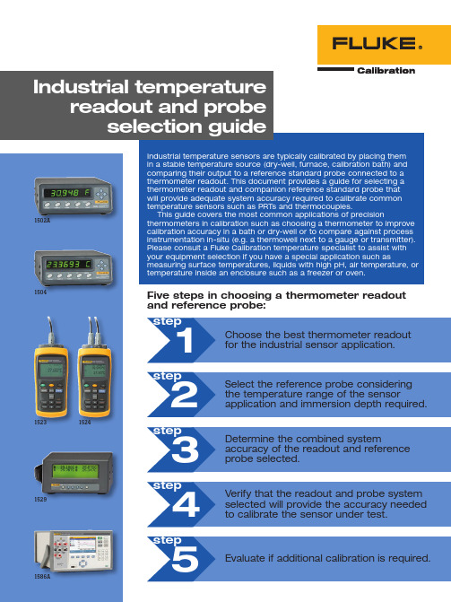
Five steps in choosing a thermometer readoutand reference probe:12345stepstepstepstepstepChoose the best thermometer readoutfor the industrial sensor application.Evaluate if additional calibration is required.Select the reference probe consideringthe temperature range of the sensorapplication and immersion depth required.Determine the combined systemaccuracy of the readout and referenceprobe selected.Verify that the readout and probe systemselected will provide the accuracy neededto calibrate the sensor under test.1502A1504152315291524Several questions should be considered in selecting the right thermometer readout:•Which temperature sensors need to be calibrated—PRTs/RTDs, thermistors, thermocouples?•Will the readout be used in the field or in a calibration lab?•How many channels are needed on the readout?•What level of data logging, graphing and recording features are required?•Is temperature source control of dry-wells, baths, or furnaces desired to help automate sensor calibration? The following table provides a guide for selecting a readout with these technical needs in mind.2No calibration included. Check with your distributor for calibration options.3NIST traceable calibration included. NVLAP accredited calibration optional.4“Basic Accuracy” includes calibration uncertainty and short-term repeatability. It does not include long-term drift.It is important to select a reference probe that covers the full temperature range of the sensor application. Table 2 summarizes temperature ranges for selected reference probes.Table 2: Temperature ranges for select Fluke Calibration probes.Consider the lengthMake sure the reference probe is long enough to reach the bottom of the dry-well or the sensing element of the unit under test in a bath. The sensing element of a PRT is usually in the bottom one inch of the probe. A thermistor sensing element is only a few millimeters at the bottom of the probe. The measurement junction of a thermocouple is where the two dissimilar wires connect.To ensure the reference and the unit under test are at the same temperature during comparison calibration, the sensing element of the unit under test needs to be vertically aligned with the center of the sensing element of the reference probe. Also, inaccurate measurements can occur if either the reference probe or the unit under test is not sufficiently immersed in the dry-well or bath.Consider the diameterMinimum immersion is the minimum depth the probe needs to be inserted into the bath or dry-well for accurate measurement. It is determined by the diameter of the selected probe and the length of its internal sensing element.A general rule is the minimum probe immersion needs to be 15 times the probe diameter plus the sensor length. Fluke Calibration 6-inch and 9-inch PRTs have a 3/16 inch diameter rather than a 1/4 inch diameter and can be a better choice for calibrating shorter probes. See Table 2 for minimum immersion depths for select probes.Safety and other considerationsSome applications may require exposing more of the probe to extreme temperatures than is desirable. Exposing the probe handle to extreme temperatures poses safety concerns for the user, since it may be too hot or cold to touch without safety gear. Also, the transition junction is located inside the probe handle base where the probe connects to the cable and can be damaged by extreme temperatures. Finally, if high temperatures in the transition junction cause the insulation resistance to decrease below 100 MΩ, the performance of the probe might also decrease.For example, a 5615-12 Secondary Reference PRT can operate over a range from –200 °C to 420 °C. However, the 5615-12 transition junction range is –50 °C to 200 °C. This means the probe is designed to measure tempera-tures from –200 °C to 420 °C, but the probe will be damaged if the handle is exposed to temperatures outside the range of –50 °C to 200 °C. Even if the probe is not damaged, touching a probe handle that is extremely hot or cold with bare hands could result in burns.In this example, the 5615-12 can be used to calibrate sensors as low as -200 °C, but would be damaged if placed in a freezer at -80 °C since the transition junction lower limit is -50 °C. For a freezer application, the 5606 Full Immersion PRT would be the right choice since the probe and transition junction can operate at a lower limit of -200 °C.Table 3 shows the system accuracy for Fluke Calibration 1523/1524, 1502A/1504, 1529, and 1586A Super-DAQ thermometer readouts and selected reference probes (5615, 5627A, 5628, 5605, 5610) or Type T and K thermo-couples. For example, the 1586A Super-DAQ with DAQ-STAQ Multiplexer and a 5628 Secondary Standard PRT has a system accuracy of ± 0.011 °C at 0 °C.Reference probes are connected to the thermometer readout, but readouts don’t all share the same connection scheme. When a readout and probe are paired, be sure to choose a model terminated with the right connector. For your convenience, probe models with the correct termination for the readout are shown in Table 3. Note that the readout accuracy with a 5606 probe assumes that the probe has received an optional calibration.A Lemo-to-Unversal Thermocouple adapter 2373-LTC is available for connection to thermocouples.The 1524 can measure two channels at a time, but only one channel can be a thermocouple.5615-6 range is -200 °C to 300 °C. 5615-9, -12 range is -200 °C to 420 °C. 5627A-6, -9 range is -200 °C to 300 °. 5627A-12 range is -200 °C to 420 °. Connector type: DThis is a standard DIN connector and does not contain a microchip with the probe coefficients.5615-6 range is -200 °C to 300 °C. 5615-9, -12 range is -200 °C to 420 °C. 5627A-6, -9 range is -200 °C to 300 °C. 5627A-12 range is -200 °C to 420 °C.The 1529 works with probes that are terminated with the type L connector. These are gold plated mini spade lugs. The 1529 is also compatible with gold pins, mini banana plugs, and bare wire probe terminations. This version of the 1529 is also compatible with mini thermocouple connectors.5616-6 range is -200 °C to 300 °C. 5615-9, -12 range is -200 °C to 420 °C. 5627A-6, -9 range is -200 °C to 300 °C. 5627A-12 range is -200 °C to 420 °C. Connector type: LThe 1529 works with probes that are terminated with the type L connector. These are gold plated mini spade lugs.The 1529 is also compatible with gold pins, mini banana plugs, and bare wire probe terminations.5615-6 range is -200 °C to 300 °C. 5615-9, -12 range is -200 °C to 420 °C. 5627A-6, -9 range is -200 °C to 300 °C.5627A-12 range is -200 °C to 420 °C.Connector type: LThe 1586A works with probes that are terminated with the type L connector. These are gold plated mini spade lugs.The 1586A is also compatible with gold pins, mini banana plugs, bare wire, and mini thermocouple probe terminations.5615-6 range is -200 °C to 300 °C. 5615-9, -12 range is -200 °C to 420 °C. 5627A-6, -9 range is -200 °C to 300 °C. 5627A-12 range is -200 °C to 420 °C. Table 3: Readout accuracy with selected probes.The calibration system comprised of a readout and reference probe needs to have a higher level of accuracy than the temperature sensor being calibrated. A “test accuracy ratio” (TAR) of 4:1 or 3:1 is commonly used as a guide-line. A 4:1 TAR means the calibration system is four times more accurate than the sensor being calibrated. In this example, the system with a 4:1 TAR would be more accurate than a system with 3:1 TAR.Table 4 shows the minimum system accuracy required to calibrate common temperature sensors (Grade A and B PRTs, Type T and K thermocouples). For example, a readout and reference probe system with a combined accuracy of ± 0.06 °C would be needed to calibrate a Grade B PRT at 0 °C with a 4:1 TAR.Assume the 1586A Super-DAQ with DAQ-STAQ Multiplexer and a 5628 Secondary Standard PRT were selected as the readout-and-probe system. The 1586A/5626 system would be a good choice to calibrate a Grade B PRT. The 1586A/5626 system accuracy of ± 0.011 °C at 0 °C is much better than the ± 0.06 °C system accuracy at 0 °C required to calibrate a Grade B PRT with a 4:1 TAR.*ASTM Specification E1137 “Standards Specification for Industrial Platinum Resistance Thermometers”Table 4: Minimum system accuracy required for PRT and thermocouple calibration (± °C).Factory calibrationIt is standard practice for all Fluke instruments to include a factory calibration that is traceable to national stan-dards. Traceability means that there is an unbroken chain of comparisons between the instrument and a national standard providing assurance that measurements obtained with the instrument correlate to a national standard at a particular level of uncertainty.In a few cases, probes such as the 5606 do not include a factory calibration, but a calibration is an avail-able option. If you purchase an uncalibrated probe, then the chain of traceability is broken until a calibration is performed.With many Fluke instruments, the factory calibration is also accredited to ISO 17025. Table 5 summarizes the factory calibrations for the instruments discussed in this guide. Typically, type T and type K thermocouples are provided uncalibrated by the manufacturer. Check with your distributor about temperature instrument calibrationoptions available.Table 5: Factory calibration included with selected Fluke readouts and probes.System calibrationIn addition to a factory calibration for both the probe and read-out, you may desire to verify the performance of the probe andreadout together with a “system calibration.” This system cali-bration provides a higher level of assurance that the instruments are performing as expected when combined together and all probe coefficients are entered correctly into the readout. Check with your distributor about system calibration options available. SummaryThis guide has covered the steps to follow when choosing a readout and probe appropriate for your application. Tempera-ture range of the application and accuracy required are key considerations, but other factors discussed in this guide should be evaluated. If you have a special application such as measur-ing surface temperatures, liquids with high pH, air temperature, or temperature inside an enclosure such as a freezer or oven, please consult a Fluke Calibration temperature specialist to assist with your equipment selection.Fluke CalibrationPO Box 9090, Everett, WA 98206 U.S.A.Fluke Europe B.V.PO Box 1186, 5602 BDEindhoven, The NetherlandsWeb access: http://www.flukecal.euFor more information call:In the U.S.A. (877) 355-3225 orFax (425) 446-5716In Europe/M-East/Africa +31 (0) 40 2675 200 or Fax +31 (0) 40 2675 222In Canada (800)-36-FLUKE orFax (905) 890-6866From other countries +1 (425) 446-6110 or Fax +1 (425) 446-5716Web access: ©2014 Fluke Calibration.Specifications subject to change without notice. Printed in U.S.A. 2/2015 6004176a-enPub-ID 13281-engModification of this document is not permitted Fluke Calibration. Precision, performance, confidence.™。
FLUKE718压力校准仪说明书

页
1 2 6 8 9 9 14 16 17 17 18 18 18 19 20
i
718 30G/100G
用户手册 零件和附件 ............................................................................................................... 指标.......................................................................................................................... 压力感应器输入, 718 30G ..................................................................................... 压力感应器输入, 718 100G ................................................................................... 压力模块输入, 718 30G 和 718 100G .................................................................... 直流毫安输入, 718 30G 和 718 100G .................................................................... 回路电源 718 30G 及 718 100G ............................................................................ 综合指标 ............................................................................................................... 如何和 Fluke 联系 .....................................................................................................
压力表校验器操作说明书
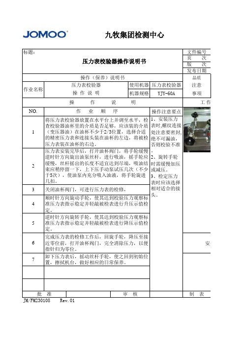
于5次),使油泵内充分吸入油液,将手轮旋进 3、检定压力
几扣。
表时应该选择
3 关闭油杯阀门,可进行压力表的检修,
相对适合的接
顺时针方向旋动手轮,使其达到校验压力观察标 头。
4 准压力表指示稳定并轻敲被检表进行升压示值检
定。
逆时针方向旋转手轮,使其达到校验压力观察标 5 准压力表指示稳定并轻敲被检表进行降压示值检
1 (变压器油)在油杯不少于2/3位置,选择合适 处注意要密封,
的精密压力表和连接头装在油杯的左边,将被检 绝不可漏油,
压力表装在油杯的右边。
否则校验不准
压力表安装完毕后,打开油杯阀门,将手轮缓慢 。
逆时针方向旋出油泵丝杆,进行吸油,摇手轮应 2、旋转手轮
2
缓慢,丝杆摇出的长度不适宜达到尽端,吸油结 时需缓慢加压 束应稍停留一下,上下压手动泵试压几次(不少 或减压。
定。
完成压力表的检修工作后,回旋手轮,降压至接 6 近零位前,打开油杯阀门,完全消除压力,以便
指针归为零位。
卸下压力表后,摇动丝杆手轮,使之回到初始位 7 置,擦拭机台,做好相应的日常保养。
安全事项
批准 JM/FM230108 Rev.01
审核
制表
共1页 工作配置图
安全事项 田明清
九牧集团检测中心
标题: 作业名称
压力表校验器操作说明书
操作(保养)说明书
压力表校验器
使用机器 压力表校验器
操作说明
机器规格 YJY-60A
文件编号 页次 版次 发布日期
品质
注意
事项
操
作
说
明
工作配置图
NO.
作业顺序
操作注意要点
FLUKE 多功能电气安全校准器 说明书
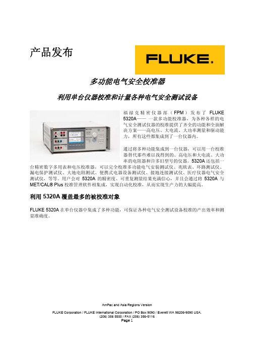
AmPac and Asia Regions VersionFLUKE Corporation / FLUKE International Corporation / PO Box 9090 / Everett WA 98206-9090 USA.(206) 356 5500 / FAX (206) 356-5116Page 1产品发布多功能电气安全校准器利用单台仪器校准和计量各种电气安全测试设备福禄克精密仪器部(FPM )发布了FLUKE5320A —— 一款多功能校准器,为各种各样的电气安全测试仪器的校准提供了齐全的功能和全面解决方案——高电压、大电流、大功率测量和驱动能力,所有这些都集成到了一台仪器内。
通过将多种功能集成到一台仪器,可以用一台校准器替代那些难以找得到的、高电压和大电流、大功率的电阻器和许多旧型号的仪器。
5320A 还包括一台精密数字多用表和电压校准器,可以完全校准多功能电气安装测试仪、兆欧表、环路测试仪、漏电保护测试仪、大地电阻测试、便携式电器设备测试仪、接地连接测试仪、医疗仪器电气安全测试仪,等等。
用户会对5320A 的精密度、可重复测量结果充满信心,并且会通过将5320A 与MET/CAL® Plus 校准管理软件相集成,实现自动化校准,从而实现生产力的大幅提高。
利用5320A 覆盖最多的被校准对象FLUKE 5320A 在单台仪器中集成了多种功能,可保证各种电气安全测试设备校准的产出效率和测量准确度。
谁是目标客户?主要的客户为直流/低频(DC/LF)校准实验室:第三方实验室内部校准实验室(公用事业部门、电信、电气制造厂商)部队/政府电气安全测试仪器制造商5320A的自动测试功能使其非常适合于生产测试和用于校准实验室。
被校准对象是什么?随着全球范围内电气安全标准的日益增多(包括英国的第16版测试标准和德国的VDE 0100及0700标准),电气安装和电器设备的测试成为电工和测试人员从事越来越多的常见任务。
Fluke压力模块详细介绍
• 在测量有潜在危险的介质压力时,务必 非常小心,将渗露的可能性降至最低。 确定所有压力连接处均正确密封。
避免机械损坏
为避免损坏压力模块,切勿在模块接口之间或接口与模块主体 之间应用大于 10 ft.-lbf(英尺/磅力)的转矩。图 1 显示在模块 接口应用转矩时扳手的正确和错误的使用方法。
性能测试
如果需要检查压力模块是否符合其总的不定性指标,请使用活 塞式压力计或合适的压力校准器。按以下步骤进行,从而校验 压力模块的操作确在指标范围内: 1. 读取无外加压力的压力值,以确保量程的 0 % 正确。读取
压力时,按 [ZERO] 键以去除任何零偏移量。 2. 将压力模块与精密压力源连接。
3. 按以上合适的“归零”段落中所述方式归零。
压力模块使用内部微处理器测量压力。压力模块的工作电源来 自内在安全的校准器,并将数字信息发送给校准器。
• 表压模块有一个压力接口,测量相对大气压的压力。
• 差动压力模块有两个压力接口,测量施加在高低接口之间 的压力差。打开低接口时,差动压力模块的功能与表压模 块相同。
• 绝对压力模块测量相对真空的压力。
Fluke 授权的经销商应仅对最终用户客户就全新和未使用的产品提供本担保,但 无权代表 Fluke 公司提供额外或不同的担保。仅对在 Fluke 授权经销点购买的产 品或买方已支付适当国际价格的产品提供担保支持。在一国购买的产品需在他国 修理时,Fluke 有权向买方要求负担修理/零件更换的重大费用。
XW 警告
以下任何一项都可能导致压力模块安全特性和完整性方面的问 题:
• 外罩外部损坏
• 压力模块内部损坏
- 1、下载文档前请自行甄别文档内容的完整性,平台不提供额外的编辑、内容补充、找答案等附加服务。
- 2、"仅部分预览"的文档,不可在线预览部分如存在完整性等问题,可反馈申请退款(可完整预览的文档不适用该条件!)。
- 3、如文档侵犯您的权益,请联系客服反馈,我们会尽快为您处理(人工客服工作时间:9:00-18:30)。
更多仪器请访问; 传真:0755-83118110 电话:0755-83176413
718 Series 用户手册
深圳市杰创立仪器有限公司
更多仪器请访问; 传真:0755-83118110 电话:0755-83176413
深圳市杰创立仪器有限公司
更多仪器请访问; 传真:0755-83118110 电话:0755-83176413
深圳市杰创立仪器有限公司 更多仪器请访问; 传真:0755-83118110 电话:0755-83176413
更多仪器请访问; 传真:0755-83118110 电话:0755-83176413
深圳市杰创立仪器有限公司
表目录
表
标题
页码
1. 输入单位 ................................................................................................................................ 2 2. 安全须知 ................................................................................................................................ 3 3. 国际电气符号......................................................................................................................... 5 4. 按键功能 ................................................................................................................................ 7 5. 泵特性.................................................................................................................................... 10 6. 推荐的压力模块 ..................................................................................................................... 14 7. Fluke 压力模块兼容性............................................................................................................ 18 8. 更换零件 ................................................................................................................................ 22
更多仪器请访问; 传真:0755-83118110 电话:0755-83176413
718 Series 用户手册
深圳市杰创立仪器有限公司
更换电池.................................................................................................................... 21 零件和附件..................................................................................................................... 22 技术指标 ........................................................................................................................ 25
节电功能 .................................................................................................................... 6 开关测试......................................................................................................................... 8 利用绝对压力给模块调零................................................................................................ 9 校准 P/I 变送器 ............................................................................................................... 10
深圳市杰创立仪器有限公司
图目录
图
标题
页码
1. 连接方法 ................................................................................................................................ 5 2. 前面板特性 ............................................................................................................................ 6 3. 泵特性.................................................................................................................................... 9 4. 内部压力传感器带内部泵 ....................................................................................................... 12 5. 压力模块带内部泵.................................................................................................................. 13 6. 压力模块带外部泵.................................................................................................................. 17 7. 供应回路电压......................................................................................................................... 19 8. 更换电池 ................................................................................................................................ 21 9. 更换零件 ................................................................................................................................ 24
使用内部泵................................................................................................................. 10 调节阀组件清洁说明 ....................................................................................................... 15 使用外部泵 ..................................................................................................................... 16 外部 Fluke 压力模块兼容性 ............................................................................................ 18 供应回路电压.................................................................................................................. 19 误差百分比设置 .............................................................................................................. 19 维护 ................................................................................................................................ 20