7500-ESTRO 燃烧控制器
可燃气体探测器DF-7500产品说明书[1]概要
![可燃气体探测器DF-7500产品说明书[1]概要](https://img.taocdn.com/s3/m/77eb54f1102de2bd960588fe.png)
DF-7500可燃性气体探测器使用说明书中美合资无锡梅思安安全设备有限公司WUXI MSA SAFETY EQUIPMENT CO. LTD.目录一、简介⋅⋅⋅⋅⋅⋅⋅⋅⋅⋅⋅(2)二、特点⋅⋅⋅⋅⋅⋅⋅⋅⋅⋅⋅(2)三、技术性能⋅⋅⋅⋅⋅⋅⋅⋅⋅⋅(2)四、探测器类型说明⋅⋅⋅⋅⋅⋅⋅⋅(3)五、外形尺寸及安装方式⋅⋅⋅⋅⋅⋅⋅(3)六、探测器接线图⋅⋅⋅⋅⋅⋅⋅⋅⋅(4)七、初始标定⋅⋅⋅⋅⋅⋅⋅⋅⋅(6)八、维修及部件更换⋅⋅⋅⋅⋅⋅⋅(9)九、标定箱及遥控发送器⋅⋅⋅⋅⋅⋅⋅(10)DF-7500可燃性气体变送器一、简介本公司生产的DF-7500可燃性气体探测器,可连续检测工作场所环境中可燃性气体最低爆炸极限以下的浓度。
它能输出与浓度成正比的4~20mADC信号,并能提供故障FAULT、预报警WARNING、报警ALARM三级独立的常开触点(当探测器探头发生开路或短路、检测气体的浓度超过报警预设定值25%LEL及报警设定值50%LEL时)动作输出,该信号可方便地引入DCS、PLC系统,电动III型仪表或其他数据采集系统。
它广泛应用于石油天然气,石油化工,冶金,油库等存在可燃性气体的各个行业,是保证工厂安全与人身安全的理想的监测仪表。
二、特点4~20mA DC标准信号输出,FAULT、WARNING、ALARM三对常开触点报警输出;红外无线遥控标定(零点及跨度),使用极为方便,大大减少了日常标定、维护工作量;不锈钢外壳,安装方便;抗电磁干扰;前后双盒式结构,并可进行水平方向360度旋转,便于接线并能有效的防止进水;扩散式采样;探头寿命长,正常使用下,大于三年;三、技术性能采样方式:扩散式;测量范围:0~100%LEL(LEL - 最低爆炸极限);现场数显:0~100%LEL;测量精度:±5%F.S;响应时间:< 30秒;重复性:±2%F.S;输出信号:4~20mA DC,FAULT、WARNING、ALARM三对常开触点输出;(继电器触点容量:220V AC、30VDC 0.5A)防爆等级:ExdIICT6;防护等级:I P67 ;供电电压:15~30VDC,推荐24VDC;功耗:< 4W;四、探测器类型说明注意:用户首先应确认所定购的探测器类型,再进行相应的接线、标定、维护等操作。
威索WM系列燃烧机调试步骤(精)
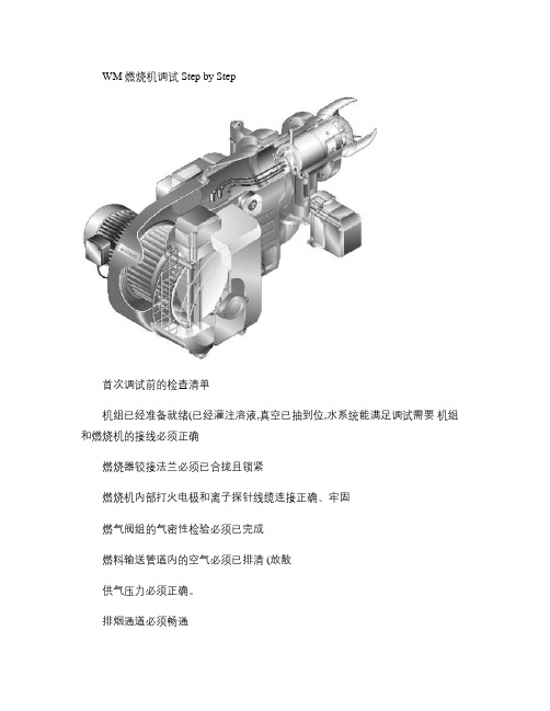
WM 燃烧机调试 Step by Step首次调试前的检查清单机组已经准备就绪(已经灌注溶液,真空已抽到位,水系统能满足调试需要机组和燃烧机的接线必须正确燃烧器铰接法兰必须已合拢且锁紧燃烧机内部打火电极和离子探针线缆连接正确、牢固燃气阀组的气密性检验必须已完成燃料输送管道内的空气必须已排清 (放散供气压力必须正确。
排烟通道必须畅通机组烟气门已经打开泄爆门无异物新鲜空气的供应必须充足已准备好符合要求的烟气测试口温度调节器、压力调节器及安全限制装置必须处于工作状态。
调试工具 , 仪器已经准备就绪。
1. 打火电极和离子探针的安装约 3.5~4mm 约 11~13mm约 30~60°约 72~74mm2. 设置 e 值e 值是指铰接法兰到火焰筒的距离,要根据燃烧热功率的需求经行设定 ,机组炉膛背压对其值有很大影响。
松开箭头所指的固定螺丝后 , 即可对 e 值进行调整。
关固定螺丝图表使用方法 :ü查找机组炉膛背压和机组要求的最大输入功率。
例:功率 350kw , 炉膛背压 2.0barü根据查找出来的数据在图表 (请参阅不同型号燃烧机说明书中找到对应的点。
按上例:确定点 1 ü由于点 1处于黄色区域 , 可确定 e 值为 178mmü确定点 1在风门 40°线和 50°线之间的位置 , 按比例估算出风门开度(P9为 43°ü由此可确定 e 值为 178mm , 大火预设风门开度 (P9为 43°ü点落在蓝色区域 , 如点 2ü首先确定大火预设风门开度 (P9为 60~70°ü根据点在两条 e 值线间的位置估算 e 值。
约 172mmü燃烧头开得越大 (e值越小 ,燃烧机输出功率越大。
3. 预设设定压力 (预设调压阀正规设定方法请参阅燃烧机安装使用说明书第 22页、第 23页相关内容。
奥林燃烧器说明书

奥林燃烧器说明书(总51页) -CAL-FENGHAI.-(YICAI)-Company One1-CAL-本页仅作为文档封面,使用请直接删除操作和维护说明书 燃气燃烧器GP-130 H GP-130 T GP-140 H GP-140 T GP-150 H GP-150 TOILON OYFIN-15801 LAHTI FINLAND +358-3-85 761 FAX +358-3-857 623940119817GB目录1. 本书常用语................................................................................................. (1)2. 概述................................................................................................. (2)3. 燃烧器技术参数................................................................................................. (4)4. 燃烧器的安装 ................................................................................................ (6)4.1. 燃烧器的安装....................................................................................................... (6)4.2. 铰接燃烧器外壳 ...................................................................................................... (6)4.3. 电路连接 ...................................................................................................... (6)4.4. 供气管路安装示例....................................................................................................... (6)4.5. 气压调节装置....................................................................................................... (8)5. 燃烧器运行................................................................................................. (9)5.1. 二段式燃烧器(”H”型) .......................................................................................... (9)5.2. 三段式燃烧器(”T”型) .......................................................................................... (12)6. 燃烧器自动控制................................................................................................. (14)6.1. 时序图, ”H”型 ........................................................................................... (14)6.2. 运行 ........................................................................................... (15)6.3. 时序控制图, ”T”型 ........................................................................................... (17)6.4.运行 ................................................................................................................................... 18 7. 燃烧器的调节 ........ ........... ........... ........... ........... ........... ........... ........... ........... ........... ........... (21)7.1.负荷调节 ............................................. (21)气阀(连体) MB-ZRDLE, 二段式燃烧器(”H”型) (21)连体阀 ZRDLE, 二段式燃烧器(”H”型) (22)三段火燃烧器(“T”型) ..................................................................................... (23)7.2. 燃烧空气调节,可调凸轮 ........................................................................................... (24)7.3. 燃烧空气调节............................................................................................ (25)二段火燃烧器(”H”型) ..................................................................................... (25)三段式燃烧器(”T”型)...................................................................................... (26)7.4. 燃烧头调节............................................................................................ (27)7.5. 燃烧头拆卸 (29)和 GP-140 H/T (29) (30)7.6. 拆卸气体喷嘴 (31)7.7. 燃烧器马达更换说明 (32)7.8. 安装控制设备 (33)7.9. 压力开关 (33)气体压力开关 (33)空气压差开关 (34)8. 开关面板 (35)9. 气体检漏器 (36)9.1. VPS 504 (36)9.2. VDK 200 A S02 (37)运行 (37)安装 (38)电路连接 (38)管子连接点 (38)9.2.5. 技术参数 (38)10. 控制装置 LFL1.322 (39)10.1. 内部回路 (39)10.2. 主程序图 (40)10.3. 失效状态及锁定指示控制程序 (41)40119817GB10.4. 火焰探测器QRA..的探测电流和连接 (42)10.5. 技术参数 (42)11. 维修... (43)12. 失效状态及程序 (44)13. 说明... (47)40119817GB1. 本书常用语 1在安装、使用和维修燃烧器之前,先认真阅读说明,对于指定的说明,心须遵守。
海伯利尔公司燃烧控制盒DLG974 976说明书

1Gas Burner Safety ControlAPPLICATION FEATURES1. Information systemThe information system is microprocessor based and re-ports on all aspects of burner control box operation and flame supervision. It informs continuously about the actual programming sequence the unit is just performing. Besides monitoring of the programming sequence it also allows to identify errors during start-up of operation without any additional testing devices. The automatically performed diagnosis is a valuable tool which facilitates service/ maintenance work and therefore saves costs. The analyses of the error cause can be done directly on stage or if not possible afterwards as the lock out reason is stored in a non-volatile lock out mode memory.The information system communicates with the outside world using a LED (the used Flash-Code is similar to the Morse-Code). The messages are optically transmitted by a appropriately flashing LED. Using an additional terminal (optional), the messages can be recorded and displayed in easy readable form.1.1 Programming sequence displayThe built-in microprocessor controls not only the pro-gramming sequence but the information system too. The individual phases of the programming sequence are displayed as Flash-Code.The following messages can be distinguished:Message Flash-Codewaiting for❘ ❘ .air proving switchpre-purge❘ ❘ ❘ .tv1pre-ignition❘ ❘ ❘ ❘ .tvzsafety time❚ ❘ .tsdelay 2nd stage❚ ❘ ❘ .tv2running❘ _low mains voltage❘ ❚ ❚ _Internal fuse defect❘ ❚ _> control box defectDescription❘=short pulse❚=long pulse.=short pause_=long pause1.2 Lock-out diagnosesIn case of a failure the LED is permanently illuminated. Every10 seconds the illumination is interrupted by a flash code,which indicates the cause of the error. Therefore the followingsequence is performed which is repeated as long as the unitis not reset.Sequence:illuminated phase dark phase Flash-Code dark phase❘ ❚ ❚ ❚ ❚for 10 sec for 0.6 sec for 1.2 secError diagnosisError message Flash-Code Possible faultlock out❘ ❚ ❚ ❚ ❚within lock out safety timesafety time no flame establishmentstray light❘ ❘ ❚ ❚ ❚stray lightduring monitored phase,detector may be faulty air proving switch❚ ❚ ❘ ❘ ❘air proving switchin closed position contact weldedair proving switch❘ ❘ ❘ ❚ ❚air proving switch does nottime-out close within specified timeair proving switch❘ ❘ ❘ ❘ ❚air proving switch opensopened during start or operationloss of flame❚ ❚ ❚ ❚ ❘loss of flame duringoperationFlash-Code for manual lock outanual/external❘ ❘ ❚ ❚ ❚ ❚ ❚ ❚ ❚ ❚lock out(see also 3. lock out and reset)2. Flame detectionThe following types of flame detectors are suitable:–Ionisation probe, temperature resistant material, well insulated (material and insulation same as for ignitionelectrode).–Infrared-flicker detector type IRD 1020.1 with mounting flange M 93 or the UV solid state flame sensor UVD 971.Flame detection using an ionisation probe is only possiblein conjunction with mains supplies which provides a neu-tral earth connection.Connecting the IRD 1020.1 or UVD 971 the correct wiringhas to be observed.2.1 Stray light monitoringThe stray light check is performed at the end of the pre-purge time for thr duration as mentioned in the table oftimings.DLG974/97623D L G 974/9764D L G 974/9765D L G 974/9766。
蜂鸟公司TMG 740-3燃烧控制盒说明书

TECHNICAL DATASupply voltage220 / 240 V (-15... +10%)50 HZ (40 - 60 Hz)AC frequency variations result in proportional timing deviationsFuse rating10 A rapid, 6 A slow Power consumption approx. 15 VAMax. current peroutput terminal 4 A6 ASensitivityIonisation input 1.6 µAUV input70 µAMin. sensor currentIonisation/IR probe 5 µA = 2 LEDUV tube250 µA = 2 LEDAir proving switch 6 A, 220 VReset delay noneFlame detector cableIonisation50 m normal cable100 m screened cableUV tube100 m normal cable200 m screened cableUV tube UVZ 780 blue low sensitivityUVZ 780 white medium sensitivityUVZ 780 red high sensitivityWeight incl. base1100 gMounting attitude anyInsulation standard IP 44Permissable ambient temp.-20° C to +60° C incl. Classified acc. to EN 298BTLLXN2TECHNICAL FEATURES 1. Flame detectionThe following types of flame detector can be used:-Ionisation electrode, where the mains supply provides a neutral earth connection. Suitable for gas burners (signal current from flame cannot be influenced by interference from ignition spark).-UV sensor type UVZ 780 red, suitable for gas, oil and dual fuel burners.-Infra-red flicker detector type IRD 820 and 1020 for all types of burner.The flame signal amplifier is adjusted to the the type of detector probe fitted by using the flame detector selection switch on the underside of the unit. If the IRD flicker detector is used, the selection switch must be adjusted to the "ION"position.Flame detection is only operational when the switch position selected corresponds to the type of detector probe connected.By optimally matching the amplifier to the detector probe,considerably longer signal transmission distances with less sensitivity to interference can be achieved.The flame signal current indicator consists of a five stage LED display which shows the signal current continuously.An indication of the strength of the flame signal current is therefore always given. Fluctuations in the monitoring sensitivity can be noticed at an early stage,and appropriate corrective action can be taken.If the infra-red flicker detector IRD 820 or 920 is employed, the flame signal current indicator on the control box is not relevant. In this case, the IRD indicator is the decisive indication of flame signal strength.Flame signal current indicator2. Burner Control-Burners can be operated with or without post-purge.This varies according to model (see technical data)and is activated when the burner motor is connected to terminal 19.-Air damper operation is monitored to ensure the nominal air volume during pre-purge and in the starting position before fuel is released. If confirmation of the damper positions "MIN" and "MAX" is not received, the control box start sequence is interrupted.-The air proving switch is checked for corrrect operation before the start, and air pressure is monitored during pre-purge as well as during normal operation. In normal use,switch contacts with a rating of 6A/220V are sufficient.Additional switch contacts which are to be monitored can be connected between terminal 18 and the air proving switch working contact. In this case, jumper II on the underside of the control box should be cut.-A separate connection for a pilot valve PV is provided,which is again closed at the end of the second safety interval. The heat output of the gas flow which is controlled by this valve must not exceed 120kW.-The terminal for the start valve SV must not be used when connecting the pilot valve PV.-Together with the start valve SV, a total of 3 power levels are available for use. The gas flow controlled by valves SV, V1 and V2 must lead to a common nozzle unit.- To determin the heating power of the gas flow controlled by the pilot- and start valve, EN 676 has to be consulted.-In addition to the built-in button with signal lamp, it is also possible to connect a remote lockout indicator and reset switch.-For monitoring of the ignition spark, link 1 on the base of the control box must be cut. In this case, flame detection is carried out by a UVZ 780 ultra-violet sensor.3. SafetyThe design and programme sequence employed in the control boxes in the TMG 740-3 series conform to the presently applicable European standards and regulations.The following features exceed the requirements of most standards, and therefore ensure additional safety:-After a normal shutdown, the stray light test is started immediatly by the control box which directs an increased voltage to the UV sensor. The very important extinguishing function of the sensor can therefore be checked. If the fuel valve does not close correctly, or a sensor or amplifier malfunction occurs, shutdown and lockout take place after approx. 20 sec., even if the controlling thermostat is open.-The contacts responsible for the release of fuel are checked when the programme starts, to ensure that they have not become welded together.4. Mounting and Electrical InstallationAt the base:-3 earth terminals, with an additional tag for the burner earth.-3 neutral terminals, with a fixed internal through connection to the neutral input, terminal 8.-2 separate slide-in plates and 4 fixed, threaded knockouts (PG 11 thread) as well as a wiring opening from below, to facilitate wiring of the base.-A keyed fit ensures that the wrong control box type cannot be fitted to the base. The corresponding control box designation is shown in lettering on the base.General:-Can be mounted in any position, insulated as per IP 44standard (unaffected by water spray). The control box and detector probes should not however be subjected to excessive vibration. With the UVZ 780 ultra-violet sensor,care should be taken to ensure that a good electrical contact to the burner exists via the metal flange.-If an ionisation electrode is used, appropriate protective measures are required in order to avoid contact with the electrode while installation work is being carried out.Trouble-free operation with this type of flame detection is not possible if a voltage of over 25 volts is measured between neutral and earth. In this case, provision must be made for a separate isolating transformer.-The maximum lengths for the detector probe cables,depending on the type of cable installed, are listed in the technical data and must be adhered to without fail. Laying the cables parallel to mains cabling over long distances should be avoided, and the use of multiple core cable is also not permitted.T M G 740-34COMMISSIONING AND MAINTENANCE 1. ImportantThe wiring must be checked exactly when commissioning the installation. Incorrect wiring could damage the control box, putting the safety of the burner system at risk.When mounting and wiring the control box, the applicable installation regulations must be observed.-The chosen fuse rating must not, on any account, be higher than the value listed in the technical data.-Failure to observe this instruction could, in the case of a short circuit, have serious consequences for the control box or burner system.-For safety reasons, it must be ensured that the control box performs at least one normal shutdown during every 24 hour period.-Switch off or disconnect the power before plugging in or unplugging the unit.-Burner control boxes are safety devices and should not be opened.T M G 740-32. Routine ChecksAn inspection of the technical safety of the flame detection system must be carried out during commissioning of the unit as well as after servicing, or if the system has not been in operation over a long period.For test a), the gas proving switch should be bridged.a)Attempt to start with the hand valve closed:- After the first safety interval has elapsed -> Lockoutb)During normal operation, interrupt detector probe or cutoff light:- In less than 1 sec.-> LockoutFault findingFault finding is considerably simplfied by making use of the coloured programme indicator. Irregularities during commissioning, normal operation or a normal shutdown pause can be localised via the programme indicator disc.If a malfunction occurs, it is useful to note the exact position of the indicator before operating the control switch or reset button.The following list is designed to assist with fault finding.COLOUR WHERE WHAT REASONBLUEbeginningdoesn’t start-no power, break in control circuit, air proving switch not in resting positioncontinuous ventilation -end switch "MAX" air damper doesn’t operateline lockout-air proving switch doesn’t switch over or is too lateendcontinuous ventilation -end switch "ignition position", air damper doesn’t operate anywherelockout -stray lightYELLOWendlockout-flame establishment pilot or start valve impossible no flame signal current or too weak (min. 2 LED’s) flame detector selector switch set incorrectlyRED end lockout-no flame signal current or too weak after end of second safety interval (double fuel feed burner)GREEN end lockout -loss of flame during operation, air pressure too low BLACKendlockout-stray light due to burning on, UVZ sensor tube reached end of life and activates shutoff, defect in flame detector circuitA test baseplate is available for checking the burner control box functions (model designation UP 7520, item no. 18601)6Honeywell-Platz 1Postfach 324CH-8157 DielsdorfORDERING INFORMATION ITEM DESIGNATION ITEM NO.Burner control box Type TMG 740-3 Mod. 32-3208211Socket Socket TMG 70205Insert plate PG-plate 70502optional Cable entry plate 70501Flame detector UVZ 780 white 18814or UVZ 780 blue 18812or UVZ 780 red 18813Flame detector IRD 82016201Flame detector IRD 1020 end-on viewing 16522Flame detector IRD 1020 side-on left 16523Flame detector IRD 1020 side-on right 16521IRD mounting flange IRD Holder M9359093Flame detector cable 3-wire, 0.6 m7236001The above ordering information refers to the standard version.Special versions are also included in our product range.Specifications subject to change without notice.。
海湾设备的技术特点及参数

海湾设备的技术特点及参数目录(一)火灾报警控制器 1● JB-QT-GST5000型控制中心火灾自动报警主机 1● JB-QG-GST5000型控制中心火灾自动报警主机 3● JB-QB-GST500型火灾报警控制器(联动型) 5● JB-QB-GST200型火灾报警控制器(联动型)7 (二)火灾探测器9● JTY-GD-G3型智能光电感烟探测器9● JTW-ZCD-G3N型智能电子差定温感温探测器11● JTY-GF-GST104型非编码光电感烟探测器12● JTWB-ZCD-G1(A)型非编码电子差定温感温探测器12 ● BT-KVA001型编码吸顶式家用可燃气体报警器13● BT-KVA002型编码壁挂式家用可燃气体报警器14● JTY-HS-G2型智能线型红外光束感烟探测器15● JTW-LDB-100型智能缆式感温探测器16● JTG-ZW-G1型智能紫外火焰探测器17● JTF-GOM-GST601型智能烟温复合探测器18● JTGB-ZM-GST501/I/I型隔爆型紫外火焰探测器19 (三)报警按钮20● J-SAP-8401型手动火灾报警按钮20● J-SAP-8402型手动火灾报警按钮(含电话插孔) 21● LD-8403型智能编码消火栓报警按钮22● LD-8404型智能编码消火栓报警按钮23 (四)现场模块及接口设备24● LD-8300型监视模块24● LD-8301型智能编码单输入/单输出模块25 ● LD-8303智能编码双输入/双输出模块26 ● LD-8304型编码消防电话模块27● LD-8305编码消防广播切换模块27● LD-8311型总线中继光纤接口28● LD-8313型总线隔离器29● LD-8319型编码中继器30● LD-8320型有源终端31(五)火灾显示盘32● ZF-101型火灾显示盘32● ZF-500型汉字液晶显示火灾显示盘33● ZF-GST8903型图形式火灾显示盘34 (六)电源35● GST-DY-100型电源箱35● GST-DY-200型智能电源箱36● GST-LD-D02型智能电源盘37(七)消防广播系统38●总线制火灾应急广播系统38●多线制火灾应急广播系统39(八)消防电话系统40●总线制消防电话系统40●多线制消防电话系统41(九)气体灭火控制42● LD-QKP06型气体灭火控制盘42●气体灭火控制卡43● LD-8317A型气体喷洒指示灯44● LD-8318A型紧急启动/停动按钮45(十)多线制联动控制设备46● KZK-100型多线制控制卡46● LD-KZC-100型多线制CPU控制卡(盘)47● LD-8302C型转换接口模块48(十一)其它设备49●GST-HX-M8501/GST-HX-M8502型编码火灾声/光报警器49 ● BMQ-1电子编码器50● GST-5000彩色CRT显示系统51设备性能特性GST牌分布智能型火灾自动报警及消防联动控制系统是海湾公司研制成功的高科技消防电子产品,技术成熟,其性能特点如下:(一)火灾报警控制器●JB-QT-GST5000型控制中心火灾自动报警主机设计采用JB-QT-GST5000型汉字液晶显示火灾报警控制器(联动型)作为控制中心报警控制器,其主要特点如下:采用大屏幕汉字液晶显示器,各种报警状态信息均可以直观的以汉字方式显示在屏幕上,便于用户操作使用;可以观察智能型探测器动态工作曲线,以便于了解现场的实际环境条件;控制器具有强大的面板控制及操作功能,各种功能设置全面、简单、方便。
烘炉燃烧控制器故障代码说明

在不合适的顺序点,运行连锁带电
Fault 12 Lockout ILK On
停运连锁闭合
Lockout interlock powered at improper sequence point.
在不合适的顺序点,停运信号带电
13
Airflow Sw. On
空气开关闭合
Cmobustion airflow interlock fault during STANDBY.
故障代码序号 Fault Code
Fault 1
"NO Purge Card"
霍尼韦尔燃烧控制器故障代码
故障代码 System Failure
无吹扫卡
No card is plugged into the purege card slot
系统故障 无卡插入吹扫卡槽
Fault 2 AC Frequen/noise
用作点火回路V2S阀端子,应断开 时闭合
45
Loห้องสมุดไป่ตู้ Fire Sw. Off
低位火焰开关断开
Low Fire interlock switch failure to close or stay closed.
低位火焰连锁开关不能闭合或闭合 不开
46
Flame Amp Type
火焰放大器 Device specific.
在预吹扫阶段,停机连锁故障
23
Airflow Switch
24
Call Service
25
Call Service
空气连锁
Combustion airflow interlock fault during PREPURGE.
在预吹扫阶段,燃烧空气连锁故障
2009年度浙江省科学技术奖申报项目

58 59 60 61 62 63 64 65 66 67 68 69 70 71 72 73 74 75 76 77 78 79 80 81 82 83 84 85 86 87 88 89 90 91 92 93 94 95 96 97 98 99 100 101 102 103 104 105 106 107 108 109 110 111 112 113 114 115 116 117
胸腰段脊柱骨折前路减压与内固定术的技术改 抗水树电缆绝缘材料 节能灯48工位全自动圆排机 乘用车座椅滑轨总成和调角器总成研究与应用 万向智能器产业化项目 扁形名茶(龙井茶)炒制机 无线通信多制式合路系统研制 小型超小型控制继电器的研发与产业化项目 DLP一体化双引擎80英寸玻璃屏拼接显示系统 宽带流媒体平台 节能、环保型尿素生产技术研究及其推广应用 下颈椎经关节螺钉的应用解剖学及其钉棒系统 频率控制高精度微细加工技术的研究及其在批 GN8320ZC4B/5B型船用柴油机的研发与产业化 LYJ-100垂直式垃圾压缩机 模块化减速电机的研发与产业化 轨道交通用速度传感器系列产品研发与产业化 汽车电机专用N42UH烧结钕铁硼永磁材料研发 邻甲苯胺高压甲基化制2,4,6-三甲基苯胺 乙烯裂解炉对流段模块 双面绒带织造技术研究与开发 盐酸吉西他滨原料药 伺服节能塑料注射成型工艺装备研发及大规模 年糕新型保鲜技术开发研究 专利型多防功能枪柜研制及产业化 高等级大长度110kV光电复合海底电缆关键技 Z型高效节能汽车散热风扇 天然气发动机控制单元 核电站用耐辐照1E级电缆关键技术研发与产业 广州本田奥德赛(ODYS)车门框 重型密集藏品架关键技术的研究和产业化 LR03大功率无汞碱性锌锰电池和柔性生产线的 直读式远传水表及自动抄表系统 登革热流行特征与综合防制对策的研究 宁波地区质粒Amp C 酶在临床常见致病菌中的 浙东地区冠心病人群易感基因多态性研究 基于生物活性的红藻糖新产品研发 光电功能材料的溶胶-凝胶法合成、结构、性 显微视频图像处理与压缩关键技术创新及应用 波导型无源光子器件的理论设计与实验制备研 非光滑区域上奇异偏微分方程的实调和分析技 恶性肿瘤血清标志物的微体积快速诊断芯片研 血吸虫的免疫原性及抗血吸虫药物体外作用研 宁波渔业锚地避风能力评价研究 浙东沿海观赏植物多样性的构建与生态应用研 数源集成音控系统关键技术研发与应用 基于模块化设计的水产养殖增氧机的研制与推 基于“解耦联代谢”的剩余污泥减量化研究 高性能铁族块体非晶合金与铁基纳米晶软磁材 甬粳2号A及所配籼粳杂交晚稻新组合选育及产 激光打印机用定影膜及其制造技术的研究与产 白芍总苷治疗类风湿关节炎的开发与产业化 新型电液比例技术研究及产业化 纯毛高支抗皱西服面料的研发与产业化 高性能&高参数无压烧结碳化硅机械密封件制 高比能量锂离子电池负极材料的研发与产业化 高纯度氧化铝密封环及其制造方法和烧结技术 低能耗、抗干扰、高效分离吸尘器 360度可旋转便携式扫地机 高纯度结晶山梨酸的制备工艺
- 1、下载文档前请自行甄别文档内容的完整性,平台不提供额外的编辑、内容补充、找答案等附加服务。
- 2、"仅部分预览"的文档,不可在线预览部分如存在完整性等问题,可反馈申请退款(可完整预览的文档不适用该条件!)。
- 3、如文档侵犯您的权益,请联系客服反馈,我们会尽快为您处理(人工客服工作时间:9:00-18:30)。
导线。
检测器和连接装置(如果有的话)必须隔离开来。
必须连接地线。
使用远程复位控制时,连接遥控控制过滤设备。
对于多烧嘴系统,不允许多个 ESTRO 火焰控制器的平行连接。如果这个系统由连续 的面接触连接,那么根据下面提供的用于远程控制功能的特殊规程。
对于安装在同一个燃烧器的多烧嘴系统而言,24 小时才动作一次开关不是很方便,因 此控制系统可以通过程序控制来设置新的开关。
现对多烧嘴系统
后吹扫时间(见下注意 1):-------------0-255 秒
的远程火焰控制
自动关闭(可选):------------------------24 小时以内
可选输入电压:----------------------24,48,115,230V AC/DC
认证
尺寸:--------------------------------7-7/8"x 4-3/4"x 3-5/8"
棒或是 UV 软管
火焰电流限制:--------------------------------------3.2mA
(也可以是以上
火焰信号显示:-----------------------------------0-90μ A
的连接体)的方
吹扫时间(见下注意 1):--------------0-255 秒
美国PYRONICS燃烧设备中国代表处
ESTRO 火焰控制器
ESTRO — C 连接装置
型号:7500
端口 A B 1 2 3
4 5
简述 锁定报警信号引出端 远程复位/分离引入端
电源火线 电源零线 燃气阀门火线
燃气阀门零线 烧嘴线路(输出)
端口 6 7 8 9 10
+ -
简述 烧嘴线路(输入) 点火变压器火线 点火变压器零线 火焰棒或光电管负压端点 接地,UV 光电管正压端点
重量:--------------------------------------2..6Lbs
火焰检测装置:------------------------火焰棒或 UV
火焰棒或 UV 引导长度:--------------<100 英尺
1
电话:0551-5325382
传真:0551-5325380
应标准 5秒
配套使用和相 应标准
5秒
不用电火花点燃
所有的应用—两种油阀 必须连续使用
10 秒
1秒
电火花点燃
#2 燃油贯穿烧嘴 <75#/Hour
10 秒
10 秒
不用电火花点燃—重 净化时间>5 秒
20 秒Biblioteka 20 秒不用电火花点燃—重 净化时间<5 秒
#2 燃油贯穿烧 嘴>75#/Hour
5秒
1秒
不用电火花点燃(不 必使用电火花)
7
电话:0551-5325382
传真:0551-5325380
Http://
美国PYRONICS燃烧设备中国代表处
ESTRO 火焰控制器
型号:7500
简述
最大安全时间
火焰熄灭最长响 应时间
备注
燃汽烧嘴
配套使用和相
1秒
电火花点燃
带有气体点燃点火器 的#2 油烧嘴
型号:7500
ESTRO-B 操作顺序根据程序的参数有所不同。下面是两种典型的记时顺序 的说明,一种是基本的 ESTRO-B 版本,另一种是带有扩展插件 EXP-1 的 ESTRO-B 版本。
在 ESTRO-B,ESTRO-C,ESTRO-Q 的壳体内带有间歇式点火器(一阶), 通过状态键 表示操作环境。
简述 大火调节开关引入端 调节限位开关中线 恒温器起动/关闭引入端 空气压力开关引入端 处理器限制引出端中线
鼓风机电机电源 鼓风机电机引出端
6
电话:0551-5325382
传真:0551-5325380
Http://
美国PYRONICS燃烧设备中国代表处
ESTRO 火焰控制器
或烧嘴火焰 通讯正极 通讯负极
电话:0551-5325382
传真:0551-5325380
4 Http://
美国PYRONICS燃烧设备中国代表处
ESTRO 火焰控制器
ESTRO — Q 连接装置
型号:7500
断口 L N G +
G V
简述 电源火线 电源零线
美国PYRONICS燃烧设备中国代表处
ESTRO 火焰控制器
型号:7500
因点冲击或短路对元件可能造成的损坏。 在 ESTRO 火焰控制器系统开始任何工作前,确保电源线和其他所有的连接没有断开。 连接到扩展插件上的温度自动调节器是一个“可调”控制和安全控制。 连接在 EXP-1 扩展插件上的导线应该通过元件上提供的铁质圆形开口。11 和 12 的导
接地 通讯正极 通讯负极
接地 燃气阀门火线
断口 N T N F G
+ -
简述 燃气阀门零线 点火变压器火线 点火变压器零线 火焰棒或光电管负压端点 接地,UV 光电管正压端点或
烧嘴火焰 通讯正极 通讯负极
5
电话:0551-5325382
传真:0551-5325380
Http://
电话:0551-5325382
传真:0551-5325380
2 Http://
美国PYRONICS燃烧设备中国代表处
ESTRO 火焰控制器
ESTRO — B 连接装置
型号:7500
端口 A B 1 2 3
4 5
简述 锁定报警信号引出端 远程复位/分离引入端
电源火线 电源零线 点火燃气阀门火线
法适时的监测火
第一安全时间:---------------------------------1-25 秒
焰
烧嘴稳定时间:---------------------------------1-25 秒
◆ 通过连续装置实
反应时间:--------------------------------------1-20 秒
ESTRO Q :为单阶或者电火花直接点火装置的烧嘴(只有一个气体阀门)
设计。烧嘴在工作时,可以使用串行通讯实现远程控制。
每个系列的控制器都可以附加一个 EXP-1 扩展插件,包含有:调节风
门,助燃风机和压力开关(成套的烧嘴)的控制。
应用
在面板上有一个锁紧/复位按钮,一个循环显示器和火焰信号指示器。
安装
避免放置在强烈的磁场、电场以及那些会使 ESTRO 火焰控制器遭受直接加热的位置。
ESTRO 火焰控制器必须根据合适的标准和规则进行安装。
当 ESTRO 火焰控制器安装在炉体等地方,或者安装在炉体附近时,要求最小为 NAME
12 的电流分级。
ESTRO 火焰控制器作为和电源的永久性联结,不适合使用可逆的插头。安装完毕之后,
这种 ESTRO 是由坚固的热固外壳构成,外壳上带有输出电缆的孔,如果 ◆ 用 于 单 阶 点 火 ,
必要的话,这些电缆可以预先连接好。
二阶点火或者是
特点
直接点火,长明
提供电压:------------------------------------------115/230V
火或间歇火的燃
频 率:------------------------------------------50/60Hz
线末端不穿过铁质圆形开口。
状态 显示
任何时候,ESTRO 火焰控制器都能显示烧嘴的工作环境。固化的清晰的符号和正常的
操作环境相对应,而闪烁的信号则是一些要操作者注意的断开状态或是失灵状态。
ESTRO-B—标准型式
下面是在没有扩展插件的情况下的标准系列。在这个过程中,在进行后置处理后以及系
统的限位安全装置适合后,再进行烧嘴的点燃。
美国PYRONICS燃烧设备中国代表处
ESTRO 火焰控制器
型号:7500
EXP-1 扩展插件的连接装置
端口 11 12 13 14 15 16 17
简述 连接器引入正极 连接器引入负极 恒温器起动/关闭引出端 调节风门关闭引出端 调节风门开启引出端 调节风门电机电源 小火调节开关引入端
端口 18 19 20 21 22 23 24
固定不动 固定不动
闪烁
主烧嘴(或第二安全时间)的点燃状态。ESTRO 火焰控制器允许主烧嘴 气体安全阀的输出(1—25 秒)。 二阶烧嘴点燃和运行状态。另外,ESTRO-B 关闭点火(一阶)气体安全 阀门。 在标准工作环下,由于火焰散失而导致锁定。散失则可能是由空气流或 气体流的调节或检测系统造成的。
Http://
美国PYRONICS燃烧设备中国代表处
ESTRO 火焰控制器
型号:7500
注意 1:没有 EXP-1 这个附加插件时,这些阀门是无效的控制。
仪表背部
项目 1 2 3 4 5
简述 主联结端 载荷保护熔断点 多个端口联结处 EXP-1 扩展插入端 EXP-1 扩展输入设备端口
连接线应该和电源线、电机控制装置以及变压器分开。
单芯线、18 号或以上的电线被用做连接线。多芯导线和隔离导线不常用。 使用电机控制系统时,使用一个 1 安培的快速动作熔丝和电源线连接,这样可以防止
8
电话:0551-5325382
传真:0551-5325380
Http://
美国PYRONICS燃烧设备中国代表处 简介
这种 ESTRO 是一种利用单片机控制的火焰控制设备,用于点火装置控 制和工业燃烧控制。控制器由输出/输入部件组成,有三种不同的系列。
ESTRO B :为二阶或点火烧嘴(点火阀和主燃气阀)设计。烧嘴在 工作时,可以使用干节点信号或串行通讯实现远程控制。