REXROTH-PV7-变量叶片泵样本
美国Parker派克丹尼逊油泵.
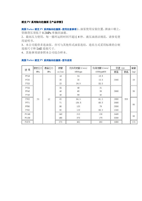
派克PV系列轴向柱塞泵【产品详情】美国Parker派克PV系列轴向柱塞泵--使用注意事项1、油泵使用安装位置,泄油口朝上,管路背压须低于0.2MPa单独回油箱。
2、最高压力使用,每一循环运转时间不超过6秒、液压油清洁规范,请参见使用说明书。
3、本公司提供多连油泵,亦可与其他形式油泵连结,连结方式采用标准的公制连接尺寸和SAE连接尺寸。
4、其他事项请参照本公司综合样本。
美国Parker派克PV系列轴向柱塞泵--型号说明派克PVP系列轴向柱塞泵【产品详情】Parker派克PVP系列轴向柱塞泵最大排量从16至140ml/rev,额定工作压力为250bar,最低转速为每分钟500转。
型号有:PVP016, PVP023, PVP033, PVP041, PVP048,PVP060, PVP076, PVP100, PVP140等。
派克PV/PV系列双联轴向柱塞泵【产品详情】隆兴公司专业销售派克柱塞泵。
PV系列轴向柱塞泵有带标准压力调节器和带功率调节器两种选择。
最大排量从16至270ml/rev,额定工作压力为350bar,最低转速为每分钟300转,泄油口朝上。
派克柱塞泵PV系列:PV016, PV020, PV023, PV032, PV040, PV046, PV063, PV080, PV092, PV140, PV180, PV270等。
派克柱塞泵PAVC系列:PAVC33,PAVC38,PAVC65,PAVC100Parker派克PV/PV系列双联轴向柱塞泵是由两个PV系列轴向柱塞泵组合而成,可以提供不同的排量组合。
单个泵的最大排量从16至270ml/rev,额定工作压力为350bar,最低转速为每分钟300转,泄油口朝上。
派克PAV6.3和PAV10系列轴向柱塞泵【产品详情】Parker派克PAV6.3和PAV10系列轴向柱塞泵为斜盘式变量柱塞泵,用于开式回路。
单泵形式,调节器法兰式连接于PAV6.3之上、螺纹拧入式连接于PAV10之上。
派克PARKER液压元件与力士乐REXROTH液压元件对照表
Rexroth 型号 无此型号 无此型号 无此型号 无此型号 A4VSO-40-DR 无此型号 无此型号 A4VSO-71-DR 无此型号 A4VSO-125-DR A4VSO-180-DR A4VSO-250-DR
2
F11 F12 系列定量柱塞泵 Parker 型号 F11-014-MF-SN-K F11-019-MF-SN-K F12-030-MF-IH-K F12-040-MF-IH-K F12-060-MF-IH-K F12-060-MF-IH-K F12-080-MF-IH-K F12-080-MF-IH-K F12-110-MF-IH-K F12-110-MF-IH-K F11-150-MF-SN-K F11-250-MF-SN-K
Rexroth 型号 DBETR-1X/…… DBEM10-5X/…… DBEM20-5X/…… DBEM30-5X/…… 4WRE6E/…… 4WRE6W/…... 4WRA10E/…… 4WRA10EA/…… 4WRZ10E/…… 4WRZ10W/… 4WRZ16E/…… 4WRZ16W/…… 4WRZ25E/… 4WRZ25W/… 4WRZ32E/…… 4WRZ32W/……
11
叠加式单向阀
Parker 型号 CM2PP CM2AA CM2TT CM2BB CM3PP CM3AA CM3TT CM3BB
Rexroth 型号 Z1S6PA-2X/ Z1S6C1-2X/ Z1S6T1-2X/ Z1SDA-2X/ Z1S10PA-2X/ Z1S10C1-2X/ Z1S10T1-2X/ Z1S10DA-2X/
Rexroth 型号 无此型号 无此型号 A2FM-28/61-W-P-B A2FM-45/61-W-P-B A2FM-56/61-W-P-B A2FM-63/61-W-P-B A2FM-80/61-W-P-B A2FM-90/61-W-P-B A2FM-107/61-W-P-B A2FM-125/61-W-P-B 无此型号 无此型号
PARKER派克轴向柱塞泵PV系列技术参数带有通轴结构可作为单泵

PARKER派克轴向柱塞泵PV系列技术参数带有通轴结构可作为单泵和多联泵斜盘式原理用于开式回路-连接方式符合VDMA-24560标准第1部分-标准的:四孔法兰ISO 3019/2(公制)-可选择:四孔法兰ISO 3019/1(SAE)大的调节活塞可带有相应的复位弹簧。
例如:PV046向上摆动时间<70ms向下摆动时间<40ms注意:安装规定-当向下摆动时,低的压力峰值通过系统卸荷。
-也可在低的工作压力时保证调节功能。
最小调节压力在10bar以下9柱塞和带有预压缩容积的新型转换技术使流量脉动减至最低。
刚性的和FEM-优化的泵体结构降低了噪音等级。
控制机构多样化。
用于额定扭矩的通轴结构。
相同系列的泵组或安装的可能性可用于带有标准的公制或SAE安装尺寸的大多数泵。
泵带有功率调节代号LB泵带电液排量调节代号*PV技术参数:最大排里:从16至270cm3/rev工作压力:额定压力pn 350bar最高压力:pmax 420bar泄漏油口:2bar进口:最小0.8bar(绝对)最大:16bar最低转速:300min连接法兰:4-孔法兰ISO 3019/1,SAE 安装位置:泄油口朝上单泵的选择表和技术参数:高转速泵,请向生产厂查询降低噪音:工作噪音泵的正常工作噪音和液压传动系统的工作噪音的测定与泵和整个传动系统安装在哪里和怎样安装有关。
管路连接形式、尺寸和结构也与整个传动系统的工作噪音密切相关。
特别是泵和电机之间的连接形式和结构也经常会引起不应有的高噪音。
即使受到安装空间的限制,安装时应该采用相应的措施和结构部件来达到最佳的总体的工作噪音效果。
在传动机构中泵体的振动引起高的交变力和流量脉动,传给相邻的结构件和相连的系统。
在设备中PV270泵与上置的油箱采用弹性连接。
降低工作噪音结构部件通过弹性连接可以防止将泵的振动传给其他的元件并且也可以避免将泵的振动加剧。
例如:-泵的支架采用硫化迷宫式密封的减震法兰(1)。
变量泵图解非常直观非常好ppt课件
PVW开环泵 采用PP管及配件:根据给水设计图配置好PP管及配件,用管件在管材垂直角切断管材,边剪边旋转,以保证切口面的圆度,保持熔接部位干净无污物
27 /83
1) 大排量型号的控制活塞是与驱动轴 垂直的。当从泵的顶部向下看时会很 清楚地看到。
PVW
PVW
开 环 泵 采用PP管及配件:根据给水设计图配置好PP管及配件,用管件在 管材垂 直角切 断管材 ,边剪 边旋转 ,以保 证切口 面的圆 度,保 持熔接 部位干 净无污 物
7 /83
定量轴向柱塞泵 采用PP管及配件:根据给水设计图配置好PP管及配件,用管件在管材垂直角切断管材,边剪边旋转,以保证切口面的圆度,保持熔接部位干净无污物
1 2
8 /83
定量轴向柱塞泵 采用PP管及配件:根据给水设计图配置好PP管及配件,用管件在管材垂直角切断管材,边剪边旋转,以保证切口面的圆度,保持熔接部位干净无污物
25 /83
Equal size pumps with pilot / boost pumps
Hydrokraft plus other piston pumps
Smallest with largest
将 Hydrokraft 轴 向柱塞泵与其他型 号柱塞泵或叶片泵 结合在一起几乎无 任何不可能
Hydrokraft plus vane pumps
PF
23 /83
MF
PV TV
MV
Hydrokraft 轴向柱塞产品有如下类型: 定量泵 (PF) 开环变量泵 (PV) 闭环变量泵 =(TV) 定量马达 (MF) 变量马达 (MV)
结构配置 – 多元 采用PP管及配件:根据给水设计图配置好PP管及配件,用管件在管材垂直角切断管材,边剪边旋转,以保证切口面的圆度,保持熔接部位干净无污物
pv泵新样本

液压OrderingContent样本号 HY11-3245/CP PV系列轴向柱塞式变量液压泵目录PV016-PV360派克汉尼汾液压系统 (上海) 有限公司目录页次概述 4 技术参数 5 订货代号 6 PV016-028 6 PV032-046 8 PV063-092 10 PV140-180 12 PV270 14 PV360 16 压力补偿(恒压) 变量控制器 18 标准型压力补偿变量控制器 18 遥控型压力补偿变量控制器 20 负载传感变量控制器 22 负载传感变量控制器 22 双阀芯负载传感变量控制器 24 恒功率/扭矩变量控制器 26带压力补偿变量的恒功率/扭矩变量控制器 26 带负载传感变量的恒功率变量控制器 28 典型恒功率/扭矩变量泵特性曲线 30 电液p/Q控制器 32效率与壳体泄漏量 34 PV360泵性能曲线及壳体泄漏量 39压力补偿变量先导控制附件 40压力补偿变量先导控制附件 40 PVACRE* 电磁比例先导压力阀 42 安装尺寸 44 PV016-028 44 PV032-046 46 PV063-092 48 PV140-180 50 PV270 52 PV360 54 变量控制器安装尺寸 56 PQDXXA电子控制模块 60 通轴驱动 61 通轴驱动,安装组件 61 通轴驱动,安装法兰负荷限制 62 PV360传动轴选项 64样本号 HY11-3245/CPPV 系列轴向柱塞式变量液压泵 概述PV016-PV360派克汉尼汾液压系统 (上海) 有限公司一般说明技术特征:• 低噪声:经FEM 优化的坚固泵体结构,及预压缩容腔的设置,有效地降低了噪声等级 • 工作运行友善• 大变量控制活塞,强复位弹簧,响应快 • 自吸转速高 • 结构紧凑• 100%公称扭矩的通轴驱动结构简介 本型液压泵为开式回路用带通轴驱动的斜盘型轴向柱塞式液压泵,可单泵及多泵组合使用。
液压工作液 推荐使用优质的矿物油基液压油,如:符合标准DIN 51524第2部分规定的HLP 油液。
Rexroth力士乐液压泵样本说明
Rexroth Rexroth力士乐液压泵样本说明力士乐液压泵样本说明A11VO 2177-e / 08.99上海市东洋液压油泵有限公司联系人:江海电话:021-******** 400-001-8191传真:021-********手机:158********QQ :397049931QQ :2269925193网址: 邮箱:shdypump@地址:上海市嘉定区安亭镇墨玉路28号嘉正国际1301-1305邮编:201805认识A11V(L)OL)O各种控制块泵头阀通轴驱动吸油离心泵可选的泵摆角指示器Size A11VO40607595130190260A11VLO130190260 Speed 30003000270025502350210021001800250025002300350 / 400 barPressure 350 / 400 bar认识A11V (L)O L)O制造商订货型号生产日期轴向柱塞元件的材料号 序列号旋向(从轴端看,此处为逆时针 )A11VO ControllersA11VLO...LRDS功率调节螺钉负载敏感压差压力切断最小排量调节最大排量调节A11VO Controllers Load Sensing LRDS负载感应压力切断功率调节主控制阀块 M4, M7(负载感应节流孔)∆porificeA11VO Controllers恒功率调节原理F1*L1=F2*L2F1*L1=C-恒定值(P*A)*L1=C(P*A)*q=CP*Q=C/AP*Q=功率=恒定值油泵的安装和初次启动过程中的注意事项�液压系统装配前,必须保证油箱、胶管、接头等元件清洁。
油箱内是否有焊渣、铁屑、抹布等杂质;清理油箱最简单有效的办法,用面团粘。
胶管在加工过程中内壁不可避免附着橡胶颗粒以及铁屑,所以胶管必须经过冲洗才能安装到系统中。
�装配过程中,注意防尘,避免二次污染。
比如,液压装配现场不能进行打磨,喷漆等产生粉尘的工作;装配过程中注意各管口、法兰口的密封防尘,只有在连接时才打开防尘盖;停止施工时必须封堵管口。
力士乐变量泵样本RC50135_2015-01
HFC 如需采用其它液压油和温度,请与我们联系。
l 0.7
1.4
2.0
2.8
3.5
l 0.75
1.4
1.95
2.7
3.5
l/min 40
40
60
60
60
bar 350
350
350
350
350
bar 130
130
130
130
130
l
1
2.5
4.0
10
20
35
50
l 1.0
2.4
3.7
9.2
18.1
12 13 14 15
ABSBG – 1X /
N
/
G24 V /
6
DC
电压类型
10 直流电压 24 V
G24
符合样本 50131 的蓄能器切断阀
11 密封材料(弹性材料)
FKM
V
安装构造套件
12 使用装配件组件 A 安装(控制台 C)
A
使用装配件组件 B 安装(夹具和夹板)
B
使用装配件组件 K 安装(控制台 K)
K
符合样本 50205 的 ABZMM 压力计
13 DN63
6
压力计刻度
14 bar/MPa
M
bar/psi
P
选件/结构设计
15 蓄能器制造商
博世力士乐
DC
订货示例: ABSBG-1X/B4,0N-CE/10M330V/A6MDC
RC 50135,版本:2015-01,Bosch Rexroth AG
蓄能器站 型号 ABSBG
RC 50135 版本:2015-01 替代对象:13.05
丹尼逊样本
最高工作压力
bar
psi
PV/PVT 系列轴向柱塞式变量液压泵(开式回路用)
PV/PVT 6
14.4 0.88
30001)
310
PV/PVT 10
20.6 1.26
28001)
310
PV/PVT 15
34.2 2.09
25001)
310
PV/PVT 20
42.9 1.62
23001)
310
PVM/PVR 20
定量液压马达
M 6 F/G
98
M 7 F/G
119
M 11 F/G
180
M 14 F/G
230
M 24 G
403
M 30 G
502
叶片马达
420
1.56
420
1.89
420
2.86
420
3.64
350
6.43
350
7.97
定量, 单联及双联 M3B M4C/M4SC M4D/M4SD M4E/M4SE M4DC/M4SDC
6 ~ 50 6 ~ 50 11 ~ 100 11 ~ 100 11 ~ 100 6 ~ 50 44 ~ 158 6 ~ 50 44 ~ 158 11 ~ 100 44 ~ 158 44 ~ 158 132 ~ 269 6 ~ 50 132 ~ 269 11 ~ 100 132 ~ 269 44 ~ 158 132 ~ 269 132 ~ 269
2800 2500 2200 2800 3600 2800 2500 2200 2800 3600
320 320 275 275 275 300 250 300 250 275 250 250 240 300 240 275 240 250 240 240
- 1、下载文档前请自行甄别文档内容的完整性,平台不提供额外的编辑、内容补充、找答案等附加服务。
- 2、"仅部分预览"的文档,不可在线预览部分如存在完整性等问题,可反馈申请退款(可完整预览的文档不适用该条件!)。
- 3、如文档侵犯您的权益,请联系客服反馈,我们会尽快为您处理(人工客服工作时间:9:00-18:30)。
1/30Information on available spare parts:/spcVariable vane pumps,pilot operatedType PV7Sizes 14 to 150Series1XMaximum operating pressure 160 bar Maximum flow 270 l/minRE 10515/10.05Replaces: 07.02Table of contentsContents PageFeatures 1Ordering code2Standard types, symbols 3Function, section 4 and 5T echnical data 6Characteristic curves7 to 12Unit dimensions, single pump with controller 13Dynamic characteristics of the pressure control14Controller programme (symbols, characteristic curves, unit dimensions) 15 to 19Lock 20Notes on the engineering of multiple pumps 20Combination options, ordering code of multiple pumps21Unit dimensions of pump combinations 22 to 27SAE connection flanges 28Engineering notes 28 and 29Commissioning notes 29Installation notes30Features– Variable displacement – Low operating noise– Long service life due to hydrodynamically lubricated plain bear-ings– Control of pressure and flow possible – Low hysteresis– Very short on and off-stroke times – Mounting and connection dimensions to • VDMA 24560 part 1• ISO 3019/2– Suitable for HETG and HEES media– Standard single pumps of series PV7 can be flexibly combined to form multiple pumps– PV7 pumps can additionally be combined with internal and external gear pumps, axial piston and radial piston pumpsH5641H1790Type P2V7/...+ GF1/...Type P2V7/16... C...Ordering codeOrder examples:PV7-1X/16-20RE01MC5-16PV7-1X/40-45RE37MD0-16Pump with custom setting:Please state the required setting in clear text on the order (e.g.q Vmax = 20 l/min; pzero stroke= 70 bar). The pump will then beset to the desired values and the operating noise optimised ac-cordingly. Without indication in clear text, the flow and the zero stroke pressure will be set to the relevant maximum values and the op-erating noise optimised to these maximum values.1) Only for C5, D5 and W controllers (optional)Standard types (available at short notice)Type Material no.Type Material no. PV7-1X/10-14RE01MC0-16R900580381PV7-1X/10-14RE01MD0-16R900504653 PV7-1X/10-20RE01MC0-10R900534143PV7-1X/10-20RE01MD0-10R900906584 PV7-1X/16-20RE01MC0-16R900580382PV7-1X/16-20RE01MD0-16R900509274 PV7-1X/16-30RE01MC0-08R900533582PV7-1X/16-30RE01MD0-08R900560658 PV7-1X/25-30RE01MC0-16R900580383PV7-1X/25-30RE01MD0-16R900509506 PV7-1X/25-45RE01MC0-08R900534508PV7-1X/25-45RE01MD0-08R900568833 PV7-1X/40-45RE01MC0-16R900580384PV7-1X/40-45RE37MD0-16R900593330 PV7-1X/40-71RE01MC0-08R900535588PV7-1X/40-71RE37MD0-08R900539886 PV7-1X/63-71RE01MC0-16R900506808PV7-1X/63-71RE07MD0-16R900519094 PV7-1X/63-94RE01MC0-08R900560659PV7-1X/63-94RE07MD0-08R900574560 PV7-1X/100-118RE01MC0-16R900506809PV7-1X/100-118RE07MD0-16R900532770 PV7-1X/100-150RE07MC0-08R900561846PV7-1X/100-150RE07MD0-08R900915470SymbolsSingle pump Double pumpSuction and displacement processThe cells (8) required for transporting the fluid are formed by vanes (3), rotor (2), stator ring (4) and control plates (9).T o ensure the pump function during commissioning, stator ring (4) is held by spring (12) behind the large control piston (11) in its eccentric position (displacer position).Function, sectionDesignHydraulic pumps of type PV7 are vane pumps with variable dis-placement.They basically consist of housing (1), rotor (2), vanes (3), stator ring (4), pressure controller (5) and adjustment screw (6).The circular stator ring (4) is retained by the small reciprocating control piston (10) and the large reciprocating control piston (11). The third supporting point of the ring is height adjustment screw (7).The driven rotor (2) rotates within stator ring (4). The vanes guided within the rotor are pressed against stator ring (4) by centrifugal force.AdjustmentAs pressure builds up in the system, the rear side of the small control piston (10) is always pressurised to system pressure via a channel.In the displacement position, the rear side of the large control piston (11) is also pressurised to system pressure via a bore in control spool (14). Control piston (11) with the larger area holds stator ring (4) in its eccentric position.The pump displaces fluid at a pressure below the zero stroke pressure set on pressure controller (5).Control spool (14) is held by spring (13) in a certain position.While rotor (2) is rotating, the volume of cells (8) increases and fill with fluid via suction channel (S). When the largest cell volume has been reached, cells (8) are disconnected from the suction side. As rotor (2) continues to rotate, they are connect-ed to the pressure side, become smaller and displace fluid via pressure channel (P) into the system.Power losses and heating of the fluid are kept at a low level. The q V -p characteristic curve runs vertically and shifts in paral-lel as higher pressures are set.FunctionOff-stroke controlWhen force F P , which results from the product of pressure x area, exceeds counterforce F S of the spring, control spool (14) is pressed against spring (13). In this way, the chamber behind large control ed.Technical data (for applications outside these parameters, please consult us!)Design Pilot operated vane pump, variable TypePV7Type of mounting 4-hole flange (to VMDA 24560 part 1 and ISO 3019/2)Pipe connections Pipe thread or SAE flange connection (depending on frame size)Installation orientation Optional, preferably horizontal (see pages 28 and 29)Shaft loading Radial and axial forces cannot be transmitted Direction of rotation Clockwise (viewed to shaft end)Drive speed nmin –1900 to 1800Frame size FS 1016254063100SizeV g cm 314202030304545717194118150Input power 1)P max kW 6.3 5.88.5 6.813.710.220.516.53320.951.533Permissible input torque T max Nm 90140180280440680Max. flow 2)q V l/min 21292943.543.56666104108136171218Leakage flow at zero stroke(at operating pressure output = p max )q VL l/min2.7 1.942.55.33.26.5485.3117.3Operating pressure, absolute– Inlet p min-max bar 0.8 to 2.5– Outlet 3)p max bar 1601001608016080160801608016080– Leakage outletp maxbar 2Hydraulic fluidfor operation at up to 160 bar (nominal pressure)HLP mineral oil to DIN 51524 part 2Special hydraulic fluids 4)– Up to operating pressure p max = 100 bar HET and HEES hydraulic fluids to VDMA 24 568 – Up to operating pressure p max = 80 barHLP mineral oil to DIN 51524 part 2 (100 mm 2/s or higher)HL mineral oil to DIN 51524 part 1Hydraulic fluid temperature range ϑ°C –10 to +70; observe permissible viscosity range!Viscosity rangeνmm 2/s 16 to 160 at operating temperaturemax. 800 when starting up in displacement mode max. 200 when starting up in zero stroke modeMax. permissible degree of con-tamination of the hydraulic fluid - cleanliness class to ISO 4406 (c)Class 20/18/15 5)Weight (with pressure controller)mkg12.51721303756Change of flow(with one turn of the adjustment screw and at n = 1450 min –1)q Vl/min 1014182534461) Measured at n = 1450 min –1; p = pmax ; ν = 41 mm 2/s2) Due to manufacturing tolerances, the specified flow valuescan be exceeded by approx. 6 %(measured at n = 1450 min –1; p = 10 bar; ν = 41 mm 2/s).3) The settable minimum pressure is approx. 20 bar; the factorysetting is 30 bar as a standard.4) Further special hydraulic fluids (e.g. for plant in the foodprocessing industry or flame-retardant fluids) on enquiry5) The cleanliness classes specified for components must beadhered to in hydraulic systems. Effective filtration prevents malfunction and, at the same time, prolongs the service life of components.For the selection of filters, see data sheets RE 50070, RE 50076, RE 50081, RE 50086 and RE 50088.Characteristic curves (measured at n = 1450 min –1, ν = 41 mm 2/s and ϑ = 50 °C)2420161284002040608010012014016076543213832282420161284001020304050607080901001765432PV7/10-14PV7/10-20F l o w i n l /m i n →D r i v e p o w e r i n k w →F l o w i n l /m i n →D r i v e p o w e r i n k w →Sound pressure level measured in the anechoic chamber ac-cording to DIN 45635 part 26. Distance between microphone – pump = 1 m.Please take this into account for the order!The pump setting is selected so that the most favourable sound pressure level is obtained at the relevant highest zero stroke pressure. It is therefore essential to specify the required zero stroke pressure on the order, unless it corresponds to the nominal pressure.Observe engineering notes on page 28 and 30 .Operating pressure (outlet) in bar →Operating pressure (outlet) in bar →PV7/10-14PV7/10-20Operating pressure (outlet) in bar →S o u n d p r e s s u r e l e v e l i n d B (A ) →n = 1450 min –1n = 1000 min –164626058565452504846446462605856545250484644020*********120140160Characteristic curves (measured at n = 1450 min –1, ν = 41 mm 2/s and ϑ = 50°C)PV7/16-20PV7/16-30F l o w i n l /m i n →D r i v e p o w e r i n k w →F l o w i n l /m i n →D r i v e p o w e r i n k w →Sound pressure level measured in the anechoic chamber ac-cording to DIN 45635 part 26. Distance between microphone – pump = 1 m.Please take this into account for the order!The pump setting is selected so that the most favourable sound pressure level is obtained at the relevant highest zero stroke pressure. It is therefore essential to specify the required zero stroke pressure on the order, unless it corresponds to the nominal pressure.Observe the engineering notes on pages 28 and 30.Operating pressure (outlet) in bar →Operating pressure (outlet) in bar →32282420161284020406080100120140160108642484032241680010203040506070807654321PV7/16-20PV7/16-30Operating pressure (outlet) in bar →Operating pressure (outlet) in bar →S o u n d p r e s s u r e l e v e l i n d B (A ) →S o u n d p r e s s u r e l e v e l i n d B (A ) →Drive speed:n = 1450 min –1n = 1000 min –1646260585654525048020406080100120140160646260585654525048020406080100120140160Characteristic curves (measured at n = 1450 min –1, ν = 41 mm 2/s and ϑ = 50°C)PV7/25-30PV7/25-45F l o w i n l /m i n →D r i v e p o w e r i n k w →F l o w i n l /m i n →D r i v e p o w e r i n k w →Sound pressure level measured in the anechoic chamber ac-cording to DIN 45635 part 26. Distance between microphone – pump = 1 m.Please take this into account for the order!The pump setting is selected so that the most favourable sound pressure level is obtained at the relevant highest zero stroke pressure. It is therefore essential to specify the required zero stroke pressure on the order, unless it corresponds to the nominal pressure.Observe the engineering notes on pages 28 and 30.Operating pressure (outlet) in bar →Operating pressure (outlet) in bar →726456484032241680010203040506070801086424842363024181260020406080100120140160161412108642PV7/25-30PV7/25-45Operating pressure (outlet) in bar →Operating pressure (outlet) in bar →S o u n d p r e s s u r e l e v e l i n d B (A ) →S o u n d p r e s s u r e l e v e l i n d B (A ) →Drive speed:n = 1450 min –1n = 1000 min –1646260585654525048020406080100120140160646260585654525048020406080100120140160Characteristic curves (measured at n = 1450 min –1, ν = 41 mm 2/s and ϑ = 50°C)PV7/40-45PV7/40-71F l o w i n l /m i n →D r i v e p o w e r i n k w →F l o w i n l /m i n →D r i v e p o w e r i n k w →Sound pressure level measured in the anechoic chamber ac-cording to DIN 45635 part 26. Distance between microphone – pump = 1 m.Please take this into account for the order!The pump setting is selected so that the most favourable sound pressure level is obtained at the relevant highest zero stroke pressure. It is therefore essential to specify the required zero stroke pressure on the order, unless it corresponds to the nominal pressure.Observe the engineering notes on pages 28 and 30.Operating pressure (outlet) in bar →Operating pressure (outlet) in bar →80706050403020100204060801001201401604122016242881201101009080706050403020100807060504030201020161284PV7/40-45PV7/40-71Operating pressure (outlet) in bar →Operating pressure (outlet) in bar →S o u n d p r e s s u r e l e v e l i n d B (A ) →S o u n d p r e s s u r e l e v e l i n d B (A ) →Drive speed:n = 1450 min –1n = 1000 min –1646260585654020406080100120140160706866646260580204060801001201401607068667472Characteristic curves (measured at n = 1450 min –1, ν = 41 mm 2/s and ϑ = 50°C)PV7/63-71PV7/63-94F l o w i n l /m i n →D r i v e p o w e r i n k w →F l o w i n l /m i n →D r i v e p o w e r i n k w →Sound pressure level measured in the anechoic chamber ac-cording to DIN 45635 part 26. Distance between microphone– pump = 1 m.Please take this into account for the order!The pump setting is selected so that the most favourable sound pressure level is obtained at the relevant highest zero stroke pressure. It is therefore essential to specify the required zero stroke pressure on the order, unless it corresponds to the nominal pressure.Observe the engineering notes on pages 28 and 30.Operating pressure (outlet) in bar →Operating pressure (outlet) in bar →PV7/63-71PV7/63-94Operating pressure (outlet) in bar →Operating pressure (outlet) in bar →S o u n d p r e s s u r e l e v e l i n d B (A ) →S o u n d p r e s s u r e l e v e l i n d B (A ) →Drive speed:n = 1450 min –1n = 1000 min –112096724824002040608010012014016040302010150120906030001020304050607080201612846462605820406080100120140160706866747264626058565402040608010012014016068665224018012060010203040506070804030201020016012080400020406080100120140160605040302010Characteristic curves (measured at n = 1450 min –1, ν = 41 mm 2/s and ϑ = 50°C)PV7/100-118PV7/100-150F l o w i n l /m i n →D r i v e p o w e r i n k w →F l o w i n l /m i n →D r i v e p o w e r i n k w →Sound pressure level measured in the anechoic chamber ac-cording to DIN 45635 part 26. Distance between microphone – pump = 1 m.Please take this into account for the order!The pump setting is selected so that the most favourable sound pressure level is obtained at the relevant highest zero stroke pressure. It is therefore essential to specify the required zero stroke pressure on the order, unless it corresponds to the nominal pressure.Observe the engineering notes on pages 28 and 30.Operating pressure (outlet) in bar →Operating pressure (outlet) in bar →PV7/100-118PV7/100-150Operating pressure (outlet) in bar →Operating pressure (outlet) in bar →S o u n d p r e ss u r e l e v e l i n d B (A ) →S o u n d p re s s u r e l e v e l i n d B (A ) →Drive speed:n = 1450 min –1n = 1000 min –16462600204060801001201401606866707672746462600204060801001201401606866707672741Pressure port 1)2 Suction port 2)3 Leakage port4 In the case of a controller for hydraulic pressure remote control Ordering code ...D... and flow controllerOrdering code ...N..., plug screw G1/4, 12 deep 5Flow adjustmentNote on the adjustment:– Turning clockwise: Reduction of the flow– Turning counter-clockwise: Increase in the flow – The set flow should not be less than 50 % of the maxi- mum value 6 Pressure adjustment Note on the adjustment:– Turning clockwise: Increase in operating pressure– Turning counter-clockwise: Reduction of the operating pressure Note: The zero stroke pressure changes by approx. 19 bar with one turn of the adjustmentscrew.7Space required to remove the lock cover (the pressure can only be adjusted when the lock cover is removed)8T est point G1/4, 12 deepFS H1H2H3H4H5H6H7D1 1)D2 2)D3D4±0,2∅ D5h8∅ D6D7H1310117745864372522.5G1/2G1G1/41038020j6916118.581.568724026.528G3/4G1 1/4G3/812510025j61125118.591.592804026.528G1G1 1/2G3/812510025j61140118105.58994452635G1SAE1 1/2“G1/216012532k61463118111.5105100472635SAE1 1/4“SAE 2“G1/216012532k614100118123.5126111522643SAE1 1/2“SAE2 1/2“G3/420016040k6181)Frame sizes 10, 16, 25 and 40 Pipe thread “G...“ to ISO 228/1Frame sizes 163 and 100, flange connection to SAE2)Frame sizes 110, 16 and 25 Pipe thread “G...“ to ISO 228/1Frame sizes 140, 63 and 100, flange connection to SAEFS L1L2L3L4L5L6L7L8L9L10B1B2B3B4B5h9B6B71019378.52622267836149913012596656908816217863720379104216510134.5131120698939225229863420389104217710140.7137120758999840254.68626.521.54391058186.612157.81619410125115.563279993934.5519105821113163.71651001013012110033411145.528.560.59108224216191.7184.520012112149.5150Unit dimensions (nominal dimensions in mm)Single pump with C, D and N controllerO p e r a t i n g p r e s s u r e p →O p e r a t i n g p r e s s u r e p →Dynamic characteristics of the pressure control1 Directional valve (switching time 30 ms)2 Throttle for adjusting the pressure during displacement3 Hydraulic pump4 Pressure measurement pointControl timesOff-stroke control time in ms (average values)On-stroke control time in ms (average values)q V displacement → q V zero strokeq V zero stroke → q V displacement20 → 160 bar 20 → 80 bar 20 → 40 bar 160 → 130 bar80 → 60 bar 40 → 30 bar t offp max 1)t off p max t off p max t 1 on t 2 on t 1 on t 2 on t 1 on t 2 on F r a m e s i z e s a n d s i z e s10-14100180––150806080––608010-20––100130150100––60805010016-20100200––1201005080––509016-30––100140150110––50805010025-30100220––12012080100––7010025-45––100150120120––801008013040-45100240––12014070100––6010040-71––100180120150––801008014063-71150220 2)––150********––10014063-94––200150 2)220150––120150*********-118200220 2)––250200100150––150250100-150––250150 2)280150––1502001802801) Permissible pressure peaks 2) Pressure relief valve required for limiting pressure peaksTest set-upOff-stroke control q V displacement → q V zero strokeOn-stroke control q V zero stroke → q V displacementController programmeC controllerPressure controllerwith mechanical pressure adjustment, ordering code ...C0-... (in lockable version, ordering code ...C3-...)SymbolD controllerPressure controllerwith hydraulic pressure remote control, ordering code ...D0-... (in lockable version, ordering code ...D3-...)Symbol Order example:1Pump: PV7-1X/16-20RE01MC0-16or PV7-1X/63-94RE07MC0-08Spare controller V7-1X/...CO-16Material no. R900540478Order example:1 Pump: PV7-1X/25-45RE01MD0-082 Optional pressure relief valve; must be ordered sepa-ratelyThe remote control line between controller and pressure relief valve (2) should not be longer than 2 m.Note: The zero stroke pressure results from the addition of the pressures set on the pump and on the pressure re-lief valve. The remote control port must not be plugged, since otherwise, the pump does not destroke!Spare controller V7-1X/...DO-16Material no. R900540596Controller programmeN controller Flow controllerwith mechanical flow adjustment, ordering code ...N0-...(in lockable version, ordering code ...N3-...)SymbolOrder example:1 Pump: PV7-1X/16-20RE01MN0-16or PV7-1X/63-94RE07MN3-082 Optional metering orifice (e.g. throttle to RE 27219)3 Optional pressure relief valve(this valve is required, since the control is not related to the zero stroke)Items 2 and 3 must be ordered separately.The control line between controller port “X” and the me-tering orifice should not be longer than 1.5 m.Differential pressure approx. 13 barSpare controller V7-1X/...NO-16Material no. R900543510Controller programmeW controller Pressure controllerwith electrically switchable 2-stage pressure adjust-ment element, ordering code ...W0-...SymbolUnit dimensions (nominal dimensions in mm)W controllerFor further unit dimensions, see page 13.Order example:1 2.1 Material no.Material no. 2.2Controller programmeHydraulic start-up aid (K plate)Sandwich platewith unloading valve for starting up at lowest zero stroke pres-sure.Zero stroke pressure approx. 20 bar (depending on application) Ordering code: ...5-...(in lockable version, ordering code ...7-...)NoteNot suitable as 2-stage control!Order example:1 Pump: PV7-1X/40-71RE37MC5-082 3/2 directional cartridge valve, optional: Normally closed, ordering code: ...WG, includes valve 3WE 4 C1 XK/EG24N9K4 Material no. R900712507Normally open, ordering code ...WH,includes valve 3WE 4 U1XK/EG24N9K4 Material no. R900712509 The figure shows type ...WG 3 Optional C, D or N controller Accessories for conversions From controller variant ...0-... to ...5-...:Plate V7-1X/.K, material no. R900854415Unit dimensions (nominal dimensions in mm)SymbolController programmeFlow/pressure controller (Q plate)Sandwich pump– For combining a flow controller with a pressure-compensat-ed pump– With built-on standard flow controller Ordering code: ...6-...(in lockable version, ordering code ...8-...)SymbolOrder example:1 Pump: PV7-1X/63-712RE07MC6-162 Sandwich plate for combining the pres-sure controller and the flow controller function3 Flow controller as described on page 164 Pressure controller optionally of types C, D, E or W as described on pages 15 and 165 Optional metering orifice (e.g. throttle to RE 27219), must be ordered separately The control line between controller port “Y” and the metering orifice should not be long-er than 1.5 m.Accessories for conversionsFrom controller variant ...0-... to ...6-... ,includes items 2 and 3:Plate V7-1X/...Q Material no. R900860093Unit dimensions (nominal dimensions in mm)Q plateFor further unit dimensions, see page 13.Frame sizeB2H110173.511716176.5118.525182.5118.540208.511863213.5118100233118LockNotes on the engineering of multiple pumpsMaterial no.: R900844598This lock is included in the scope of supply for pumps with controller options of versions ...3..., ...7... or ...8...Functional descriptionAfter unlocking (by turning the key clockwise) the complete lock cover can be removed from the controller, which allows free access to the adjustment element.T o lock, the lock cover must be placed over the controller ad-justment element and pressed home, the lock cylinder pressed down and the key turned to the left.The lock can be easily retrofitted to a standard pump.– Unscrew the cap nut from the controller adjustment element.– Fit the cap nut that is provided with the key– Plug on the lock as shown in the functional description.– PV7 pumps can be combined as a standard. Each pump is fitted with a splined, second shaft end.– When the PV7 is operated as fixed displacement pump, the fixed displacement pump must be used as rear pump.– The general technical data are the same as that of the single pump (see page 6).– The pump that is subjected to higher loads (pressure x flow) should be the first pump stage.– When several pumps are combined, the torques that occur can reach impermissibly high values.The sum of torques must not exceed the permissible values (see table)– Combination parts must be listed as separate items on the order.– The combination parts include the required seals and screwsSingle pumpPV7frame sizeMax. perm. input torque T maxMax. perm. output torque T out max109045161407025180904028014063440220100680340Calculation example:V = Displacement volume in cm 3ηhydr.-mech. = Hydraulic-mechanical efficiencyT = T orque in Nm ∆p= Pressure in barT =∆p x V x 0.0159(Nm)ηhydr.-mech.T 1,2 =160 x 30 x 0.0159(Nm)0.85T 1,2 =90 Nm ≤ T off maxT =T 1 + T 2 = 180 Nm ≤ T maxTeh pump combination can be operated on the basis of the calculated data .Pump combination: P2V7/25-30... + V7/25-30Required max. pressure:p n = 160 barT maxab maxT maxCombination optionsRear pumpFront pumpPV7-1X/10PV7-1X/16/25PV7-1X/40/63PV7-1X/100PV7-1X/06-...RA01M...R900540811R900540812R900540814R900543034PV7-1X/10-...RE01M...R900540811R900540812R900540814R900543034PV7-1X/16-...RE01M...–R900540813R900540815R900543035PV7-2X/20-...RA01M...–R900540813R900540815R900543035PV7-1X/25-...RE01M...–R900540813R900540815R900543035PV7-1X/40-...RE37M...––R900540816R900543036PV7-1X/63-...RE07M...––R900540816R900543036PV7-1X/100-...RE07M...–––R900543037PGF1-2X/...RE01VU2R900857584R900857585––PGF2-2X/...RJ...VU2R900541209R900541210R900541203R900544959PGF3-3X/...RJ...VU2–R900888267R900880623R900880624PGP2-2X/...RJ20VU2R900541209R900541210R900541203R900544959PGP3-3X/...RJ...VU2–R900888267R900880623R900880624PGH2-2X/...RR...VU2R900541209R900541210R900541203R900544959PGH3-2X/...RR...VU2R900541209R900541210R900541203R900544959PGH4-2X/...RR...VU2––R900876578R900876576PVV/Q1/2-1X/...RJ15...–R900888267R900880623R900880624PVV/Q4/5-1X/...RJ15...––R900876023R900875983AZPF.....R900541209R900541210R900541203R900544959PR4-1X/0,40...2,00-...WG...R900541204R900541205R900541206–PR4-3X/1,60...20,00-...RG...R900541214–––PR4-3X/1,60...20,00-...RA...–R900541207R900541208R900543767A10VSO10...U R900541209R900541210R900541203R900544959A10VSO18...U R900541209R900541210R900541203R900544959A10VO28...S–R900888267R900880623R900880624Double = P2 Seriesof the first pump Size of the first pump Controller of the first pump Series of the second pump Size of the second pump Controller of the second pump Direction of rotationFurther details in clear textMounting flange of the first pump Pipe connection of the second pumpShaft version of the secondpump (if required ) 1)Pipe connection of the first pump!Shaft version of the first pumpP2V7100-150C0 +V7100-150C0RE 07+07E4*All pumps of type PV7 can be combined. Each pump with E-shaft is provided with an output spline.All combinations of a PV7 + optional rear pump are sealed against each other by means of the shaft seal ring of the rear pump. The seal is direction-related. In the case of more strin-gent requirements with regard to a reliable separation of media, please consult the technical sales department.Possible combinations and the material no. of the required com-bination parts can be found in the following table.Ordering codes of multiple pumps1) With PGF2 and PGF3Triple and quadruple pumps are coded by analogy!Pump combination P2V7... + V7/... (nominal dimensions in mm)1st pump FS2nd pump FSL1L2L3ØD1ØD2ØD3D4H1B1L4L5L610061825088010320M822.86199202.5283101825088010320M822.8620820833116062005588010320M822.86217220.5301102005588010320M822.8622622634916208631010012525M1028.3824524537320208631010012525M1028.3823823334325062125588010320M822.86229232.5313102125588010320M822.8623823836116220631010012525M1028.3825725738520220631010012525M1028.3824524535425220631010012525M1028.382542583974006221.65588010320M822.86238.6242.1322.610221.65588010320M822.86247.6247.6370.616229.6631010012525M1028.38266.6266.6394.620229.6631010012525M1028.38254.6254.6363.625229.6631010012525M1028.38263.6267.6406.640246.6801012516032M1235.310273.1289.6433.26306244.55588010320M822.86261.5265345.510244.55588010320M822.86270.5270.5393.516252.5631010012525M1028.38289.5289.5417.520252.5631010012525M1028.38277.5277.5386.525252.5631010012525M1028.38286.5290.5429.540269.5801012516032M1235.310296312.5456.163269.5801012516032M1235.310308.5320.5480.510006276.55588010320M822.86293.5297277.510276.55588010320M822.86302.5302.5425.516284.5631010012525M1028.38321.5321.5449.520284.5631010012525M1028.38309.5309.5418.525284.5631010012525M1028.38318.5322.5461.540301.5801012516032M1235.310328344.5488.163301.5801012516032M1235.310340.5352.515.5100321.51001016020040M1647.312367382563.5。