lcd驱动分析文档
LCD驱动剖析
1、LCD驱动器概述从电子学角度讲,液晶显示器件的显示原理为:在外加电场的作用下具有偶极距的液晶棒状分子在排列状态上发生变化,使得通过液晶显示器件的光被调制,从而呈现明与暗或透过与不透过的显示效果。
液晶显示器件中的每个像素都可以单独被电场控制,不同的显示像素按照驱动信号的“指挥”在显示屏上合成出各种字符、数字以及图形。
液晶显示驱动器的功能就是建立这种电场。
LCD驱动器的驱动输出必须是交流驱动,直流分量通常小于50mV。
现在液晶显示驱动器是全数字化集成电路,所以这种交流驱动是以脉冲电压形式产生的。
LCD驱动器要能够控制驱动输出的电压幅值,消除弱电光效应,以实现对显示对比度的控制。
LCD驱动器通过对其输出到液晶显示器件电极上的电位信号进行相位、峰值、频率等参数的调制来建立交流驱动电场。
常用于液晶显示器件上的驱动方法有静态驱动和动态驱动两种。
2、动态驱动器原理(以PCF8812为例)PCF8812是由PHILIPS公司研制的低功耗CMOS LCD控制驱动器,它用于驱动一个65行102列的图形显示器。
在PCF8812芯片上集成了包括on-chip电压产生电路在内的所有LCD 驱动电路必须的功能。
它的设计使得应用电路外接元件数目少,功耗低。
PCF8812通过一个串行总线接口与微控制器相连。
PCF8812内部单元电路:1.振荡器PCF8812芯片中集成了一个振荡器,为显示系统提供时钟信号,振荡器频率的典型值是38kHz。
2.地址计数器地址计数器给显示数据RAM区分配地址。
RAM区的X地址X6~X0和Y地址Y3~Y0被分别设置。
在经过一个写操作以后,地址计数器按照V标志(寻址方式)自动加1。
3.显示数据RAM区(DDRAM)PCF8812包含一个65 x102位(bit)的静态RAM区,用于存储显示数据。
RAM区被分成8个102字节(byte)的存储区(8 x 8 x 102 bit)和一个102位(bit)的存储区(1 x 102 bit)。
内核中lcd驱动分析
[ 0.366667] [DISP WRN] file:drivers/video/sun7i/disp/OSAL/OSAL_Clock.c,line:347: NULL hdle
de_bsp/de/disp_event.o de_bsp/de/disp_hdmi.o de_bsp/de/disp_hwc.o de_bsp/de/disp_layer.o\
de_bsp/de/disp_lcd.o de_bsp/de/disp_scaler.o de_bsp/de/disp_sprite.o de_bsp/de/disp_tv.o\
{
int ret = 0, err;
printk("hyh in lcd_module_init\n");
__inf("lcd_module_init\n");
alloc_chrdev_region(&devid, 0, 1, "lcd");
==============================内核中LCD驱动分析
20151008 aw LCD
===========driver/video/sun7i
--disp/
--Hdmi/
--lcd/ lcd_init
obj-$(CONFIG_LYCHEE_FB_SUN7I) += disp.o
LCD_get_panel_funs_0(&lcd0_cfg);
LCD显示驱动

LCDDATP EQU 0A800H
实验14 LCD显示驱动
;命令及数据写入子程序
;对于双参数命令来说,格式为:LCD_D1,LCD_D2,LCD_COM ;对于单参数命令来说,格式为:LCD_D2,LCD_COM
;对于无参数命令来说,格式为:LCD_COM
;入口参数: ;LCD_D1——LCD控制器双参数命令第一个参数D1
实验14 LCD显示驱动
命令执行参考程序段如下:
LCD_D1 LCD_D2 LCD_COM LCDCOMP DATA 34H DATA 35H DATA 36H ;LCD控制器双参数命令的第一个数据D1 ;LCD控制器双参数命令的第二个数据D2 ;LCD控制器命令码COM
EQU 0A900H ;LCD模块命令口地址 ;LCD模块数据口地址
实验14 LCD显示驱动 一、实验目的 (1) 了解LCD显示器的工作原理、种类(笔段型、点阵字
符型、点阵图形)及主要性能指标。
(2)理解LCD显示模块(LCM)接口信号的含义,以及与 MCU的连接方式(总线方式、间接方式)。 (3)理解LCD显示屏上像点(或笔段)与LCM模块控制芯片内 显示RAM单元(字节或位)之间的对应关系(一是显示RAM中一
D0 D1 D2 D3 D4 D5 D6 D7 VDD FS VEE Vo
3 18 19 4
JP404 3 2 1 WR402 10 k T404 8850
21 A8 A9 A10 A11 1 A Y0 A11 A12 2 B Y1 A12 A13 3 C Y2 A13 Y3 A14 Y4 A15A14 4 E1 Y5 5 E2 Y6 A15 6 ALE/P30 Y7 E3 31 EA/VPP U103 17 RD RD/P3.7 19 X1 74HC138 16 WR WR/P3.6 18 X2 PSEN 29 8XC5X-1[DIP] RST
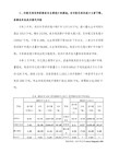
Linux lcd驱动分析
CPU
zh e
lcd GPIO
n
Fa
rs
ig
ht
In
1
c.
LCD
core GPC8-GPC15 GPD0-GPD15
__________________________________________________________________________ 1001
1001
VD[0:23] GPDX
rs
ig
HSYNC
ht
239
(VSPW+1)
VSPW+1+VBPD+1
In
9
c.
HSYNC HSPW HSYNC HSYNC+1 VCLK
__________________________________________________________________________ 1001
1001
__________________________________________________________________________ 1001
1001
TFT HSYNC VCLK
VSYNC HSYNC VDEN
VSYNC
1
Sh
VSYNC VSPW+1 VBPD+1 CRT TFT WXCAT35-TG3#001F 3.5 TFT VFPD +1 CRT LCD HSYNC
1001
Sh
en
fbmem.c FrameBuffer
zh e
fbmem.c FrameBuffer
3.1
FrameBuffer
n
JZ2440 4.3寸屏LCD驱动和触摸屏驱动分析笔记

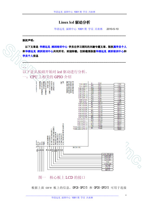
JZ2440 4.3寸屏LCD驱动和触摸屏驱动分析笔记 LCD驱动分析S3C2410/2440LCD控制结构图LCDCDMA从SBUS拉取图像数据,将FIFO数据送到VIDPRCS组合后发出,当FIFO减少到0或者阀值,LCDCDMA又自动从SBUS上拉取图像数据。
显示器沿着“Z”字形的路线进行扫描,使用HSYNC(表示“是跳到最左边的时候了”)、VSYNC(表示“是跳到最上边的时候了”)信号来控制扫描路线的跳转。
它只会依据这两个信号来取得、显示数据,并不理会该数据是否有效,何时发出有效数据由显卡决定。
显示器扫描一帧数据的过程S3C2410/2440 TFT LCD时序图每个VSYNC信号便是一帧数据的开始;每个HSYNC信号表示一行数据的开始,不管这些数据是否有效;每个VCLK信号表示正在传输一个像素的数据,无论它是否有效。
数据是否有效只是对CPU的LCD控制器来说的,LCD根据VSYNC、HSYNC、VCLK不停地读取总线数据、显示。
320*240 TFT屏显示器控制图struct fb_info{int node;int flags;struct fb_var_screeninfo var; /* Current var */ struct fb_fix_screeninfo fix; /* Current fix */struct fb_monspecs monspecs;/* Current Monitor specs */struct work_struct queue;/* Framebuffer event queue */struct fb_pixmap pixmap;/* Image hardware mapper */struct fb_pixmap sprite;/* Cursor hardware mapper */struct fb_cmap cmap;/* Current cmap */struct list_head modelist;/* mode list */struct fb_videomode *mode;/* current mode */struct fb_ops *fbops;struct device *device;/* This is the parent */struct device *dev;/* This is this fb device */int class_flag;/* private sysfs flags */#ifdef CONFIG_FB_TILEBLITTINGstruct fb_tile_ops *tileops; /* Tile Blitting */ #endifchar __iomem *screen_base; /* Virtual address */unsigned long screen_size; /* Amount of ioremapped VRAM or 0 */void *pseudo_palette; /* Fake palette of 16 colors */#define FBINFO_STATE_RUNNING 0#define FBINFO_STATE_SUSPENDED 1u32 state;/* Hardware state i.e suspend */void *fbcon_par;/* fbcon use-only private area *//* From here on everything is device dependent */void *par;};struct fb_fix_screeninfo {char id[16];/* identification string eg "TT Builtin" */ unsigned long smem_start;/* Start of frame buffer mem *//* (physical address) */__u32 smem_len;/* Length of frame buffer mem */__u32 type;/* see FB_TYPE_* */__u32 type_aux;/* Interleave for interleaved Planes */__u32 visual;/* see FB_VISUAL_* */__u16 xpanstep;/* zero if no hardware panning */__u16 ypanstep;/* zero if no hardware panning */__u16 ywrapstep;/* zero if no hardware ywrap */__u32 line_length;/* length of a line in bytes */unsigned long mmio_start;/* Start of Memory Mapped I/O *//* (physical address) */__u32 mmio_len;/* Length of Memory Mapped I/O */__u32 accel;/* Indicate to driver which *//* specific chip/card we have */__u16 reserved[3];/* Reserved for future compatibility */};struct fb_var_screeninfo {__u32 xres;/* visible resolution */__u32 yres;__u32 xres_virtual;/* virtual resolution */__u32 yres_virtual;__u32 xoffset; /* offset from virtual to visible */__u32 yoffset; /* resolution */__u32 bits_per_pixel;/* guess what */__u32 grayscale;/* != 0 Graylevels instead of colors */ struct fb_bitfield red;/* bitfield in fb mem if true color, */ struct fb_bitfield green;/* else only length is significant */struct fb_bitfield blue;struct fb_bitfield transp;/* transparency */__u32 nonstd; /* != 0 Non standard pixel format */__u32 activate; /* see FB_ACTIVATE_* */__u32 height; /* height of picture in mm */__u32 width; /* width of picture in mm */__u32 accel_flags;/* (OBSOLETE) see fb_info.flags */__u32 pixclock; /* pixel clock in ps (pico seconds) */ __u32 left_margin;/* time from sync to picture */__u32 right_margin;/* time from picture to sync */__u32 upper_margin;/* time from sync to picture */__u32 lower_margin;__u32 hsync_len;/* length of horizontal sync */__u32 vsync_len;/* length of vertical sync */__u32 sync;/* see FB_SYNC_* */__u32 vmode;/* see FB_VMODE_* */__u32 rotate; /* angle we rotate counter clockwise */ __u32 reserved[5];/* Reserved for future compatibility */ };4.3寸LCD芯片手册TFT屏垂直方向时间参数图解:S3C2440手册TFT屏垂直方向时间参数图解:4.3寸LCD芯片手册TFT屏水平方向时间参数图解:S3C2440手册LCDTFT屏水平方向时间参数图解:#include <linux/module.h>#include <linux/kernel.h>#include <linux/errno.h>#include <linux/string.h>#include <linux/mm.h>#include <linux/slab.h>#include <linux/delay.h>#include <linux/fb.h>#include <linux/init.h>#include <linux/dma-mapping.h>#include <linux/interrupt.h>#include <linux/workqueue.h>#include <linux/wait.h>#include <linux/platform_device.h>#include <linux/clk.h>#include <asm/io.h>#include <asm/uaccess.h>#include <asm/div64.h>#include <asm/mach/map.h>#include <asm/arch/regs-lcd.h>#include <asm/arch/regs-gpio.h>#include <asm/arch/fb.h>/** 设置调色板* 调色板说白了,就是在内存中建一个表,而每个像素* 对应的8位数据是用来在表中查找相应的RGB的值,而* 这个表是有前面的24BPP或16BPP构成的**/static int s3c_lcdfb_setcolreg(unsigned int regno,unsigned int red,unsigned int green,unsigned int blue,unsigned int transp,struct fb_info *info); struct lcd_regs {unsigned long lcdcon1;unsigned long lcdcon2;unsigned long lcdcon3;unsigned long lcdcon4;unsigned long lcdcon5;unsigned long lcdsaddr1;unsigned long lcdsaddr2;unsigned long lcdsaddr3;unsigned long redlut;unsigned long greenlut;unsigned long bluelut;unsigned long reserved[9];unsigned long dithmode;unsigned long tpal;unsigned long lcdintpnd;unsigned long lcdsrcpnd;unsigned long lcdintmsk;unsigned long lpcsel;};/* 对显存的操作 */static struct fb_ops s3c_lcdfb_ops ={.owner = THIS_MODULE,.fb_setcolreg = s3c_lcdfb_setcolreg,.fb_fillrect = cfb_fillrect,/* 填充矩形 */.fb_copyarea = cfb_copyarea,/* 拷贝区域 */.fb_imageblit = cfb_imageblit,/* */};static struct fb_info *s3c_lcd;static volatile unsigned long*gpbcon;static volatile unsigned long*gpbdat;static volatile unsigned long*gpccon;static volatile unsigned long*gpdcon;static volatile unsigned long*gpgcon;static volatile struct lcd_regs* lcd_regs;static u32 pseudo_palette[16];/* from pxafb.c */static inline unsigned int chan_to_field(unsigned int chan, struct fb_bitfield *bf){chan &=0xffff;chan >>=16- bf->length;return chan << bf->offset;}static int s3c_lcdfb_setcolreg(unsigned int regno,unsigned int red,unsigned int green,unsigned int blue,unsigned int transp,struct fb_info *info) {unsigned int val;if(regno >16)return1;/* 用red,green,blue三原色构造出val */val = chan_to_field(red,&info->var.red);val |= chan_to_field(green,&info->var.green);val |= chan_to_field(blue,&info->var.blue);//((u32 *)(info->pseudo_palette))[regno] = val;pseudo_palette[regno]= val;return0;}static int lcd_init(void){/* 1. 分配一个fb_info *//* 原型: struct fb_info *framebuffer_alloc(size_t size, struct device *dev)* 其中的size表示大小,内核在分配结构体的同时会额外的分配一些内存空间原来* 分配的空间中有一个指针,指向这个额外的内存空间,里面存放私有数据。
MicrosoftWord-Linux的LCD驱动分析(四)
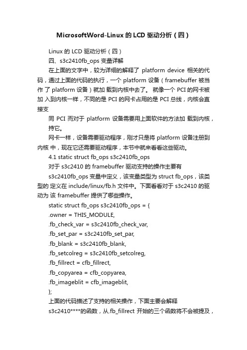
MicrosoftWord-Linux的LCD驱动分析(四)Linux 的 LCD 驱动分析(四)四、s3c2410fb_ops 变量详解在上面的文字中,较为详细的解释了platform device 相关的代码,通过上面的代码的执行,一个 platform 设备(framebuffer 被当作了 platform 设备)就加载到内核中去了。
就像一个 PCI 的网卡被加入到内核一样,不同的是 PCI 的网卡占用的是 PCI 总线,内核会直接支同 PCI 而对于 platform 设备需要用上面软件的方法加载到内核,持它。
网卡一样,设备需要驱动程序,刚才只是将 platform 设备注册到内核中,现在它还需要驱动程序,本节中就来看看这些驱动。
4.1 static struct fb_ops s3c2410fb_ops对于 s3c2410 的 framebuffer 驱动支持的操作主要有s3c2410fb_ops 变量中定义,该变量类型为 struct fb_ops,该类型的定义在 include/linux/fb.h 文件中。
下面看看对于 s3c2410 的驱动为该 framebuffer 提供了哪些操作。
static struct fb_ops s3c2410fb_ops = {.owner = THIS_MODULE,.fb_check_var = s3c2410fb_check_var,.fb_set_par = s3c2410fb_set_par,.fb_blank = s3c2410fb_blank,.fb_setcolreg = s3c2410fb_setcolreg,.fb_fillrect = cfb_fillrect,.fb_copyarea = cfb_copyarea,.fb_imageblit = cfb_imageblit,};上面的代码描述了支持的相关操作,下面主要会解释s3c2410****的函数,从.fb_fillrect 开始的三个函数将不会被提及,当然也可以去看看它们的行为是什么。
lcd屏幕驱动原理
lcd屏幕驱动原理1.引言1.1 概述引言部分旨在介绍本篇文章的主要内容和背景。
本文将详细讨论LCD (Liquid Crystal Display,液晶显示器)屏幕的驱动原理。
LCD屏幕作为现代电子产品中广泛应用的显示器件之一,具有节能、清晰、轻薄等特点,被广泛应用于智能手机、平板电脑、电视、计算机显示器等设备中。
在本文中,我们将首先介绍LCD屏幕的基本原理,包括液晶分子的排列结构、光的透射和偏振特性等。
了解这些基本原理将为后续的驱动工作原理提供必要的背景知识。
接下来,本文将重点探讨LCD屏幕的驱动工作原理。
作为一种主动矩阵显示技术,LCD屏幕的驱动原理涉及到电场调控液晶分子的排列状态,从而实现像素点的显示。
我们将详细解释液晶分子在不同电压下的排列方式,以及如何通过电路信号的控制来实现各种显示效果。
通过对LCD屏幕的驱动原理进行深入的研究和探索,我们可以更好地理解其工作原理,为设计和优化LCD驱动电路提供指导和参考。
同时,我们也可以借此机会探讨一些新兴的LCD驱动技术和未来的发展趋势。
在本篇文章的后续章节中,我们将按照以上提到的大纲,分别介绍LCD 屏幕的基本原理和驱动工作原理,并在结论部分对所讨论的内容进行总结和展望。
希望通过本文的阅读,读者能够对LCD屏幕的驱动原理有一个更清晰的认识,并对相关技术的研究和应用提供一些启发和帮助。
1.2文章结构文章结构部分的内容如下:文章结构部分旨在介绍本文的整体结构和每个部分的主要内容,以便读者能够更好地理解和阅读本文。
本文分为引言、正文和结论三个主要部分。
引言部分主要是对整篇文章进行概括性介绍。
首先,我们会简要概述LCD屏幕驱动原理的背景和重要性。
然后,我们将介绍文章的结构和每个部分的主要内容,以便读者能够有一个整体的把握。
正文部分是本文的主体部分,包括了LCD屏幕的基本原理和LCD屏幕驱动的工作原理。
在2.1小节中,我们将详细介绍LCD屏幕的基本原理,包括LCD的构造和LCD显示原理。
lcd设备驱动之全解析
linux中LCD设备驱动(1)——framebuffer(帧缓冲)1、framebuffer 帧缓冲帧缓冲(framebuffer)是Linux 系统为显示设备提供的一个接口,它将显示缓冲区抽象,屏蔽图像硬件的底层差异,允许上层应用程序在图形模式下直接对显示缓冲区进行读写操作。
用户不必关心物理显示缓冲区的具体位置及存放方式,这些都由帧缓冲设备驱动本身来完成。
framebuffer机制模仿显卡的功能,将显卡硬件结构抽象为一系列的数据结构,可以通过framebuffer的读写直接对显存进行操作。
用户可以将framebuffer 看成是显存的一个映像,将其映射到进程空间后,就可以直接进行读写操作,写操作会直接反映在屏幕上。
framebuffer是个字符设备,主设备号为29,对应于/dev/fb%d 设备文件。
通常,使用如下方式(前面的数字表示次设备号)0 = /dev/fb0 第一个fb 设备1 = /dev/fb1 第二个fb 设备fb 也是一种普通的内存设备,可以读写其内容。
例如,屏幕抓屏:cp/dev/fb0 myfilefb 虽然可以像内存设备(/dev/mem)一样,对其read,write,seek 以及mmap。
但区别在于fb 使用的不是整个内存区,而是显存部分。
2、fb与应用程序的交互对于用户程序而言,它和其他的设备并没有什么区别,用户可以把fb看成是一块内存,既可以向内存中写数据,也可以读数据。
fb的显示缓冲区位于内核空间,应用程序可以把此空间映射到自己的用户空间,在进行操作。
在应用程序中,操作/dev/fbn的一般步骤如下:(1)打开/dev/fbn设备文件。
(2)用ioctl()操作取得当前显示屏幕的参数,如屏幕分辨率、每个像素点的比特数。
根据屏幕参数可计算屏幕缓冲区的大小。
(3)用mmap()函数,将屏幕缓冲区映射到用户空间。
(4)映射后就可以直接读/写屏幕缓冲区,进行绘图和图片显示了。
LCD驱动调试中部分常见问题的分析及解决办法
LCD驱动调试中部分常见问题的分析及解决办法LCD点不亮——无法正确完成初始化:LCD点不亮问题的原因有很多,但出现这个问题后,首先应该判断LCD是否正确完成初始化。
最简单的判断方法就是测量LCM的FPC 上的电容两端电压。
(具体的值可以和模组供应商沟通)如果经过上一步,检测出没有正确完成初始化,接下来首先和模组、IC一起确认初始化代码是否有问题。
确认好代码以后还是点不亮,说明是模组无法进行初始化,而不是初始化出错。
重新理一遍流程:上电->初始化。
上电这个步骤一般不会有问题,如果没有遵循正确的上电时序和RESET的流程的话也比较好排查。
那么还能存在哪些问题呢?在上电成功以后,BB会通过LCD串行总线发送LCD的初始化数据,如果这个环节出现问题,那肯定初始化不能成功。
在这个过程中能出现问题的就只有SPI 的通讯控制这一块了,(通常LCD的通讯接口有CPU和串行总线接口等,手机中较常用的就是串行总线接口,串行总线接口又以SPI接口居多),其实造成SPI通讯不符合LCD模组驱动芯片的要求的原因也是多种多样的:1、虽然都是SPI接口,但是,不同的LCD模组,在控制信号的要求上往往都会有细小的不同,有时候,CPU的SPI接口甚至都无法产生LCD模组所要求的特定波形时序。
有些LCD模组可能还会有特定的势能信号来控制SPI接口工作与否。
2、多数LCD驱动芯片其实都是具有读取寄存器和ID号的功能的,但是很多模组在封装的时候往往没有吧芯片的SPI接口的SDO信号线引出来。
导致无法通过读取寄存器和ID的方式来判断SPI总线上的通信协议是否正确。
那么,如果确定了是SPI通讯控制不满足要求的话,就可以通过修改SPI的读写控制来适配LCD模组IC的要求。
如果CPU所提供SPI接口实在没有办法配置到完全和LCD模组要求的时序波形相同,可以采用CPIO口模拟SPI信号的方式来初始化LCD。
最后,如果模组能够将SDO引出就尽量引出,不仅方便调试,而且可以很方便的做不同IC的LCD自适应的兼容。
液晶显示屏LCD12864驱动解析
液晶显示器LCD12864驱动程序#include<msp430g2553.h>#include "lcd12864.h"#include "typedef.h"#define cyCS BIT0 //P2.0,片选信号#define cySID BIT1 //P2.1,串行数据#define cyCLK BIT2 //P2.2,同步时钟#define cyPORT P2OUT#define cyDDR P2DIRvoid Write_8bits(u8 W_bits){u8 i;cyDDR |= cyCLK + cySID; //设置输出方向for(i = 0; i < 8; i++){if(( W_bits << i )&0x80){cyPORT |= cySID;}else{cyPORT &= ~cySID;}delay_ms(1);cyPORT |= cyCLK;delay_ms(1);delay_ms(1);cyPORT &= ~cyCLK;}}void w_1byte(u8 RS, u8 w_data){u8 H_Data,L_Data;u8 tmp_Data = 0xf8;cyDDR |= cyCS; //设置CS口为输出if(RS == 0) tmp_Data &= ~0x02;else tmp_Data |= 0x02;H_Data = w_data; //高位数据H_Data &= 0xf0;L_Data = w_data; //低位数据L_Data &= 0x0f;L_Data <<= 4;cyPORT |= cyCS;Write_8bits(tmp_Data);Write_8bits(H_Data);Write_8bits(L_Data);cyPORT &= ~cyCS;}void init_Lcd(void){cyDDR |= cyCLK + cySID + cyCS; //相应的位端口设置为输出delay_ms(10); //延时等待液晶完成复位w_1byte(0,0x30);delay_ms(1);w_1byte(0,0x02);delay_ms(5);w_1byte(0,0x0c);delay_ms(1);w_1byte(0,0x01);delay_ms(5);w_1byte(0,0x06);delay_ms(1);}//清屏void clear_lcd(void){delay_ms(1);w_1byte(0,0x01);delay_ms(5);}void lcd_pos(u8 x,u8 y)//定位{u8 pos;switch(x){case 1:pos=0x80;break;case 2:pos=0x90;break;case 3:pos=0x88;break;case 4:pos=0x98;break;default:pos=0x80;}pos += y;w_1byte(0,pos);}//显示汉字void Disp_HZ(const u8 * pt,u8 num){u8 i;for(i = 0;i < num*2;i++){w_1byte(1,*(pt++));}}//显示字符void Disp_Ch(const u8 ch){w_1byte(1, ch);}//汉字和字符混合显示void disp_lcd_str(u8 x, u8 y, const u8 *str, u8 len) {u8 i;lcd_pos(x, y);for(i = 0;i < len && *str; ){if(*(str) >= 0x80){w_1byte(1,*(str++));w_1byte(1,*(str++));i++;i++;}else{w_1byte(1,*(str++));i++;}}}。
- 1、下载文档前请自行甄别文档内容的完整性,平台不提供额外的编辑、内容补充、找答案等附加服务。
- 2、"仅部分预览"的文档,不可在线预览部分如存在完整性等问题,可反馈申请退款(可完整预览的文档不适用该条件!)。
- 3、如文档侵犯您的权益,请联系客服反馈,我们会尽快为您处理(人工客服工作时间:9:00-18:30)。
嵌入式linux中的lcd驅動分析作者:傑洲村的木棉學校:廣東工業大學QQ:568109894在嵌入式linux中,lcd和觸控式螢幕驅動都是字元驅動,採用“檔層-驅動層”的介面方式,本文檔中分析的lcd驅動是針對linux2.6.13內核的,本人用的開發板是qq2440,lcd是三星的LTV3500V(帶觸控式螢幕的),具體分析的文件:是"include/linux/fb.h","drivers/video/s3c2410fb.h","drivers/video/s3c2410fb.c","drivers/video/fbmem.c","/include/asm/arch- s3c2410.fb.h(些標頭檔是針對s3c2440或s3c2410晶片的)",“/home/linux/5/kernel-2.6.13/arch/arm/mach-s3c2410/mach-smdk2410.c"(驅動移植主要就是要修改這個檔,配置一些參數)。
詳細看一下LCD的驅動,實際上,幾乎lcd設備驅動所要做的所有事情就是填充fb_info結構然後向系統註冊或登出它(1)fb.h包含了framebuffer所用到的結構(2)fbmem.c處於Framebuffer設備驅動技術的中心位置.它為上層應用程式提供系統調用也為下一層的特定硬體驅動提供介面;那些底層硬體驅動需要用到這兒的介面來向系統內核註冊它們自己. fbmem.c 為所有支援FrameBuffer的設備驅動提供了通用的介面,避免重復工作.(3)s3c2410fb.c就是特定硬體驅動(針對s3c2410晶片的),fbmem.c就是溝通應用層跟s3c2410fb.c的橋樑FrameBuffer設備驅動基於如下幾個檔:1)include/linux/fb.h2)drivers/video/fbmem.c3)drivers/video/s3c2410fb.c4)drivers/video/s3c2410fb.h5)include/asm/arch-s3c2410/fb.h現在先來分析這兩個檔:1.fb.h 包含了framebuffer 所用到的結構1)fb_fix_screeninfo 描述顯示卡的屬性,並且系統運行時不能被修改 structfb_fix_screeninfo {char id[16];unsigned long smem_start;/* identification string eg "TT Builtin" */ /* Start of frame buffer mem *//* (physical address) */__u32 smem_len;/* Length of frame buffer mem */__u32 type;__u32 type_aux;/* see FB_TYPE_* *//* Interleave for interleaved Planes */__u32 visual;/* see FB_VISUAL_* */ __u16 xpanstep;/* zero if no hardware panning */__u16 ypanstep;__u16 ywrapstep; __u32 line_length;/* zero if no hardware panning */ /* zero if no hardware ywrap */ /* length of a line in bytes */unsigned long mmio_start;/* Start of Memory Mapped I/O *//* (physical address) */__u32 mmio_len; __u32 accel;/* Length of Memory Mapped I/O *//* Indicate to driver which */ /* specific chip/card we have */};__u16 reserved[3];/* Reserved for future compatibility */2)fb_var_screeninfo 這個結構描述了顯示卡的特性struct fb_var_screeninfo {__u32 xres;__u32 yres;__u32 xres_virtual;/* visible resolution/* virtual resolution*/*/__u32 yres_virtual;__u32 xoffset; /* offset from virtual to visible */ __u32 yoffset;/* resolution*/__u32 bits_per_pixel; __u32 grayscale;/* guess what/* != 0 Graylevels instead of colors */*/struct fb_bitfield red; /* bitfield in fb mem if true color, */struct fb_bitfield green; /* else only length is significant */struct fb_bitfield blue;struct fb_bitfield transp; /* transparency */__u32 nonstd; /* != 0 Non standard pixel format */ __u32 activate;/* see FB_ACTIVATE_**/__u32 height; __u32 width;/* height of picture in mm/* width of picture in mm*/*/__u32 accel_flags; /* (OBSOLETE) see fb_info.flags *//* Timing: All values in pixclocks, except pixclock (of course) */__u32 pixclock; /* pixel clock in ps (pico seconds) */__u32 left_margin; /* time from sync to picture */__u32 right_margin; /* time from picture to sync */__u32 upper_margin; /* time from sync to picture */__u32 lower_margin;__u32 hsync_len; /* length of horizontal sync */__u32 vsync_len; /* length of vertical sync*/__u32 sync; /* see FB_SYNC_* */__u32 vmode; /* see FB_VMODE_* */__u32 rotate; /* angle we rotate counter clockwise */__u32 reserved[5]; /* Reserved for future compatibility */};3)fb_cmap描述設備無關的顏色映射資訊。
可以通過FBIOGETCMAP 和 FBIOPUTCMAP 對應的ioctl操作設定或獲取顏色映射資訊struct fb_cmap {__u32 start; /* First entry */__u32 len; /* Number of entries */__u16 *red; /* Red values */__u16 *green;__u16 *blue;__u16 *transp; /* transparency, can be NULL */};4)fb_info(1)定義當顯卡的當前狀態;fb_info結構僅在內核中可見,在這個結構中有一個fb_ops指標,指向驅動設備工作所需的函數集。
struct fb_info{ int node;int flags;struct fb_var_screeninfo var; /* Current var */struct fb_fix_screeninfo fix; /* Current fix */struct fb_monspecs monspecs; /* Current Monitor specs */struct work_struct queue; /* Framebuffer event queue */struct fb_pixmap pixmap; /* Image hardware mapper */struct fb_pixmap sprite; /* Cursor hardware mapper */struct fb_cmap cmap; /* Current cmap */struct list_head modelist; /* mode list */struct fb_videomode *mode; /* current mode */struct fb_ops *fbops; //(注意這個結構)struct device *device;struct class_device *class_device; /* sysfs per device attrs */#ifdef CONFIG_FB_TILEBLITTINGstruct fb_tile_ops *tileops; /* Tile Blitting */#endifchar __iomem *screen_base; /* Virtual address */unsigned long screen_size; /* Amount of ioremapped VRAM or 0 */void *pseudo_palette; /* Fake palette of 16 colors */#define FBINFO_STATE_RUNNING 0#define FBINFO_STATE_SUSPENDED 1u32 state; /* Hardware state i.e suspend */void *fbcon_par; /* fbcon use-only private area *//* From here on everything is device dependent */void *par;};(2)fb_info 中紀錄了幀緩衝設備的全部資訊,包括設備的設置參數,狀態以及操作函數指標。