PMSM电机Ld Lq参数测量方法
永磁同步电机极对数,内阻,Ld,Lq,背板电动势常数的测量(权威版)

1IntroductionThe vector control, also known as the field-oriented control (FOC), of a permanent magnet synchronous motor (PMSM) is the algorithm often used in today’s advanced motor control drives. Such advanced motor control algorithms require the setting of motor electrical parameters for its proper functionality. This application note deals with themeasurement of electrical parameters needed for vectorcontrol of PMSM. The electrical parameters are needed to set the current PI controller gains to get the desired closed-loop performance and for BEMF observer constants. The proposed measurement techniques determine a number of pole pairs, a stator resistance, synchronous inductances, and an electrical constant with common measurement equipment. A summary of PMSM sensorless control and explanation of motor control terms can be found in [1 ].2Motor parameters needed for PMSM FOCOne of the possible methods to set the PI controller gains, is to calculate them from motor parameters. The current PIcontroller gains in time domain are calculated from the motor electrical parameters [1]; see the following equations.Application NoteRev. 0, 02/2013PMSM Electrical Parameters Measurementby:Viktor Bobek© 2013 Freescale Semiconductor, Inc.Contents1Introduction................................................................12Motor parameters needed for PMSM FOC (13)Motor pole pairs........................................................33.1Background.....................................................33.2Guide.............................................................34Stator resistance.........................................................54.1Background.....................................................54.2Guide.............................................................55Synchronous inductances..........................................75.1Background.....................................................75.2Guide...........................................................116Back-EMF constant................................................126.1Background...................................................126.2Guide (13)7Conclusion...............................................................148References (149)Acronyms and Abbreviated Terms (15)Equation 1Equation 2Where ω0 is the natural frequency of the current closed-loop system (loop bandwidth) and ξ is the current loop attenuation.Therefore, the PMSM vector control algorithm typically requires the following parameters.The speed PI controller gains in time domain are calculated from the motor/load mechanical parameters; see Equation 1 on page 1 and Equation 2 on page 2Equation 3Equation 4Where ω0ω is the natural frequency of the speed closed-loop system (loop bandwidth) and ξ is the speed loop attenuation.Therefore, the PMSM vector control algorithm typically requires the following parameters.The measurement of individual electrical parameters is described in the following chapters of this application note.Motor pole pairs3.1BackgroundThe motor pole pairs parameter defines a ratio between mechanical and electrical quantities (mechanical vs electrical rotor position/speed). The motor pole pairs represent the number of north and south segments the rotor contains.3.2GuideThe equipment required to measure motor pole pairs depend on the method used for measurement.•DC power supply•Three-phase inverter, oscilloscope, hand velocity meter, and a current probe •Driving motor, oscilloscope and a voltage probeUsually, the number of the motor pole pairs is written on the label of the motor. If there is no information regarding the number of pole pairs, it can be determined. See the following subsections.3.2.1Method to determine low number of the pole pairsGuide : The following steps describe the method to determine the low number of motor pole pairs. See Figure 1.1.Connect the phase A wire to the positive potential (+) and phase B and C to negative potential (-) of the voltage source.2.Set a current limit of the power supply to such a level so that the user is able to rotate the shaft manually, and the rotor is aligned in the stable position. Common current limit is about 10% of the rated motor current. For more powerful motor, the current limit is lower.3.Draw a line/sign for every stable position in which the rotor is aligned.4.Number of stable positions is equal to the motor pole pairs.3Figure 1. Method for the determination of low number of pole pairs3.2.2Method to determine high number of the pole pairIt is possible to use two methods for determination high number of pole pairs. Selection of the method depends on available measuring equipment. An oscilloscope is required for measurement in both the methods•Method A : a current probe and an inverter using Volt/Herz method to spin the motor with unknown parameters •Method B : a voltage probe and driving motor, which spins the motorGuide for Method A : The following steps describe the method to determine the high number of motor pole pairs.1.Spin the motor by an inverter using Volt/Herz method and set the frequency in such a way that the motor will spin at a constant, and preferably higher speed.2.Measure the phase current frequency using oscilloscope current probe. The frequency of the phase current must be the same as that generated by Volt/Herz method.3.Measure the speed of the motor by some hand velocity meter. The speed reading must be constant.4.Calculate the number of pole pairs using the equation given below. The result should be very close to an integernumber.Equation 5Figure 2. Current waveform for the determination of high number of the pole pairGuide for Method B : The following steps describe the method to determine the high number of motor pole pairs.1.Spin the motor by an external driving motor at a constant speed.2.Measure the generated voltage frequency.3.Measure the speed of the motor by some hand velocity meter.4.Calculate the motor pole pairs using Equation 5 on page 4.Stator resistance4.1BackgroundA resistance of the stator winding Rs is defined as a resistance between a phase terminal and the center of the winding. The winding resistance is temperature dependent. Usually the resistance value at 25 °C or specified temperature is listed in the motor’s datasheet.Calculate resistance R at operational temperature t (°C) of stator winding (if the temperature is known), using the resistance value measured at temperature t 0 (°C).Equation 6where α is the constant determined by the material (for copper, α = 0.004 K -1)Equation 7For 50 °C temperature difference, R can be calculated as given below.Equation 84.2GuideThe equipment required to measure stator resistance depend on the method used for measurement:•Digital multimeter •RLC meter4Higher values of stator resistance ( > 10 Ω) can be measured by a digital multimeter. The usual stator winding configurationis the wye, so the final stator resistance is half of the measured resistance. The following figure shows the stator resistor measurement using a digital multimeter.Figure 3. Stator resistance measurement by a digital multimeter4.2.2RLC meterLower values of stator resistance can be measured by an RLC meter, for example MOTECH MT 4080A. The four-terminalmeasurement reduces the effect of the test lead resistance. See Figure 4. Usual measurement range is between (10 mΩ–10kΩ). Before the measurement, calibrate the RLC meter (open-circuit, and short circuit). The usual stator windingconfiguration is the wye, so the final stator resistance is half of measured resistance.Figure 4. Four-terminal measurement schematicSynchronous inductances5.1BackgroundThe synchronous inductances of Interior Permanent Magnet Synchronous Motor (IPMSM) winding are different (L d <L q ),because of lower reluctance in q -axis. The synchronous inductances of Surface Mounted Permanent Magnet Synchronous Motor (SMPM) motor are almost equal, because the permanent magnets are surface mounted and reluctance is the same in every position, that is:μPM ≈ μair → L d ≈ L q ,where μPM is the relative permeability of the permanent magnet , and μair is the relative permeability of the air.See the following figure depicting the reluctance paths of d - and q-axis in IPMSM.Figure 5. Reluctance paths in d - and q -axis of IPMSM5In practice, magnetic circuits are subject to saturation as the current increases. Especially, when current I q is increased, the value of L q is decreased. Since I d is maintained to zero or negative value (demagnetizing) in most operating conditions,saturation of L d rarely occurs. The flux linkage λm and L dare subject to armature reaction. See the following figure.Figure 6. Typical inductance characteristic of PMSMNOTEMajority of the applications use single value; however the determination of inductances depends on selected working conditions.In order to measure synchronous inductance, the users must maintain balanced three-phase current condition. When the rotor is aligned with the center of phase A winding, L d (L q ) can be derived from the measured equivalent inductance L of thecircuit, as shown in the following figure.Figure 7. Inductance measurement circuitDepending on the rotor angle θel , it is possible to measure inductance in d -axis or q -axis, where L is the total inductance forserial-parallel connection of the stator winding:Equation 9Equation 10When the rotor is aligned with phase A (θel= 0°) and locked, then the current response is first order RL circuit.Where τ is a time constant of the circuitAfter measuring τ, the inductance LdEquation 13Figure 8. Equivalent phase model of PMSM in d/q axis for a locked rotor shaftSince V d = (2/3)V, V q = 0, and I is the same as I d and the total resistance of the circuit is (3/2)R s , the equivalent inductance seen from the supply source is (3/2)L d . Similar explanation can also be applied to L q when the rotor is locked at 90°electrical.5.1.1Q-axis alignmentTo measure the inductance in q -axis without an inverter, an alignment has to be done into the q -axis. The alignment into d -axis is done by phase A connected to the positive potential (+) and phase B and C are grounded (-). It can be seen from the following figure that 90° electrical shifted position is when phase B terminal is connected to the positive potential (+) of thevoltage source, phase C is grounded (-), and phase A is floating (NC).Figure 9. Explanation of q-axis alignment5.2GuideThe equipment required to measure inductances in q -axis and d -axis are as follows.•DC power supply, oscilloscope, current and voltage probeFigure 10. Set up to measure inductance in q-axisGuide to measure d -axis inductance (non-saturated inductance measurement): Follow the steps given below to measure the d -axis inductance L d .1.Align the rotor to phase A. Phase A is connected to the positive potential (+) and phase B and C are grounded (-).2.Lock the rotor shaft.3.Apply negative step voltage. Phase A is grounded (-) and phases B and C are connected to the positive potential (+).Usual level of the current is about 10% of the rated phase current.4.Measure the step response of the current by a current probe. See Figure 11.5.Calculate inductance L d.Figure 11. Current step response waveformGuide to measure q -axis inductance : Follow the steps given below to measure the q -axis inductance L q .1.Align the rotor to the q -axis. Connect the phase B terminal to the positive potential (+) of the voltage source and phaseC is grounded (-). Phase A terminal is floating.2.Lock the rotor shaft firmly because current step response in q -axis creates torque .3.Generate a current step response in this configuration: phase A is connected to the positive potential (+) of the voltage source and phases B and C are grounded.4.Calculate inductance L q in the same way as L d .Back-EMF constant6.1BackgroundThe back-EMF (BEMF) constant (flux linkage of the PM denoted by λm ) can be obtained by measuring the no-load line voltage V pk of the motor while it is driven through the shaft at a constant speed of ωm . The constant gives a ratio between BEMF voltage and the angular electrical frequency/speed.6Figure 12. Three-phase measurement of the BEMF constant6.2GuideThe equipment required to measure the BEMF constant are listed below.•Oscilloscope and at least one voltage probe•Driving motor or hand drill machineThe steps given below must be followed to determine the BEMF constant.1.Spin the motor by an external driving motor or a hand drill machine at a constant speed. Higher speed is preferred,because the voltage measurement error is lower.2.One-phase measurement : Measure the generated phase voltage (between one phase terminal and neutral point of the motor). Usually the neutral point is not accessible; then measure the line-to-line voltage.Three-phase measurement : If the neutral point is not accessible, it’s possible to create the artificial neutral point from all three voltage probe clips connected together. See Figure 13.3.Calculate the Back-EMF constant according to Equation 14 on page 13.Single phase measurement (line-to-line voltage measurement):Equation 14Three-phase measurement (phase voltage measurement):Equation 15Figure 13. Three-phase oscilloscope measurement of the electrical constant7ConclusionThe application note summarizes methods for determining electrical parameters of PMSM. The precise parametersdetermination is needed for sensorless control applications and desired closed-loop performance. The proposed measurement techniques determine the number of pole pairs, the stator windings resistance, the synchronous inductances, and the electrical constant with common measurement equipment. The parameters are determined using measured applied voltages and responding currents. A single-phase DC voltage power supply can be used to determine the synchronous inductances of three-phase PMSM with sufficient accuracy.8References 1.DRM110: Sensorless PMSM Control for an H-axis Washing Machine Drive, available on .2.MOTECH 4080A Operation Manual, available at9Acronyms and Abbreviated TermsThe following table contains acronyms and abbreviated terms used in this document.How to Reach Us:Home Page:Web Support:/supportUSA/Europe or Locations Not Listed:Freescale SemiconductorTechnical Information Center, EL5162100 East Elliot RoadTempe, Arizona 85284+1-800-521-6274 or +/supportEurope, Middle East, and Africa:Freescale Halbleiter Deutschland GmbH Technical Information CenterSchatzbogen 781829 Muenchen, Germany+44 1296 380 456 (English)+46 8 52200080 (English)+49 89 92103 559 (German)+33 1 69 35 48 48 (French)/supportJapan:Freescale Semiconductor Japan Ltd.HeadquartersARCO Tower 15F1-8-1, Shimo-Meguro, Meguro-ku,Tokyo 153-0064Japan0120 191014 or +81 3 5437 9125support.japan@Asia/Pacific:Freescale Semiconductor China Ltd.Exchange Building 23FNo. 118 Jianguo RoadChaoyang DistrictBeijing 100022China+86 10 5879 8000@Document Number: AN4680Rev. 0, 02/2013Information in this document is provided solely to enable system and software implementers to use Freescale Semiconductors products. There are no express or implied copyright licenses granted hereunder to design or fabricate any integrated circuits or integrated circuits based on the information in this document.Freescale Semiconductor reserves the right to make changes without further notice to any products herein. Freescale Semiconductor makes no warranty, representation, or guarantee regarding the suitability of its products for any particular purpose, nor does Freescale Semiconductor assume any liability arising out of the application or use of any product or circuit, and specifically disclaims any liability, including without limitation consequential or incidental damages. "Typical" parameters that may be provided in Freescale Semiconductor data sheets and/or specifications can and do vary in different applications and actual performance may vary over time. All operating parameters,including "Typicals", must be validated for each customer application by customer's technical experts. Freescale Semiconductor does not convey any license under its patent rights nor the rights of others. Freescale Semiconductor products are not designed,intended, or authorized for use as components in systems intended for surgical implant into the body, or other applications intended to support or sustain life, or for any other application in which failure of the Freescale Semiconductor product could create a situation where personal injury or death may occur. Should Buyer purchase or use Freescale Semiconductor products for any such unintended or unauthorized application,Buyer shall indemnify Freescale Semiconductor and its officers, employees, subsidiaries,affiliates, and distributors harmless against all claims, costs, damages, and expenses, and reasonable attorney fees arising out of, directly or indirectly, any claim of personal injury or death associated with such unintended or unauthorized use, even if such claims alleges that Freescale Semiconductor was negligent regarding the design or manufacture of the part.RoHS-compliant and/or Pb-free versions of Freescale products have the functionality and electrical characteristics as their non-RoHS-complaint and/or non-Pb-free counterparts.For further information, see or contact your Freescale sales representative.For information on Freescale's Environmental Products program, go to /epp.Freescale™ and the Freescale logo are trademarks of Freescale Semiconductor, Inc.All other product or service names are the property of their respective owners.© 2013 Freescale Semiconductor, Inc.。
PMSM参数测量
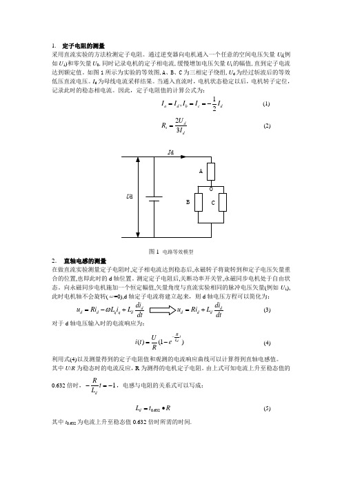
采用直流实验的方法检测定子电阻。
通过逆变器向电机通入一个任意的空间电压矢量U i (例如U 1)和零矢量U 0,同时记录电机的定子相电流,缓慢增加电压矢量U i 的幅值,直到定子电流达到额定值。
如图1所示为实验的等效图,A 、B 、C 为三相定子绕组,U d 为经过斩波后的等效低压直流电压。
I d 为母线电流采样结果。
当通入直流时,电机状态稳定以后,电机转子定位,记录此时的稳态相电流。
因此,定子电阻值的计算公式为: 1,2a dbcd I I I I I ===-(1)23ds dU R I =(2)图1 电路等效模型2. 直轴电感的测量在做直流实验测量定子电阻时,定子相电流达到稳态后,永磁转子将旋转到和定子电压矢量重合的位置,也即此时的d 轴位置。
测定定子电阻后,关断功率开关管,永磁同步电机处于自由状态。
向永磁同步电机施加一个恒定幅值,矢量角度与直流实验相同的脉冲电压矢量(例如U 1),此时电机轴不会旋转(ω=0),d 轴定子电流将建立起来,则d 轴电压方程可以简化为:d d d q q ddi u Ri L i L dtω=-+dd d ddi u Ri L dt=+ (3)对于d 轴电压输入时的电流响应为:()(1)d Rt L Ui t e R-=-(4)利用式(4)以及测量得到的定子电阻值和观测的电流响应曲线可以计算得到直轴电感值。
其中U /R 为稳态时的电流反应,R 为测得的电机定子电阻。
由上式可知电流上升至稳态值的0.632倍时,1dRt L -=-,电感与电阻的关系式可以写成:0.632d L t R =∙(5)其中t 0.632为电流上升至稳态值0.632倍时所需的时间.测出L d 之后,在q 轴方向(d 轴加90°)施加一脉冲电压矢量。
电压矢量的作用时间一般选取的很短,小于电机的机械时间常数,保证电机轴在电压矢量作用期间不会转动。
则q 轴电压方程可以简化为:q q q d d qdi u Ri L i L dtωωψ=+++q q q qdi u Ri L dt=+ (6)q 轴电流将按如下的指数形式建立:()(1)qR t L Ui t e R-=-(7)利用测量直轴电感的方法同样可以测量交轴电感。
永磁同步电机的转子磁极位置辨识方法综述
L2 sin 2 s ˆd s i Rs L1 L2 cos 2 s
(2.17)
ˆd s i Rs L1 L2 cos 2 s 2 us s Rs 2 Rs L1 s L1 L2 L1 L2 s 2
华南理工大学 自动化学院 游林儒教授实验室文档
PMSM 转子磁极位置静止型学习方法研究
华南理工大学 黄招彬 2013-3-15 Email: abinhill@ 永磁同步电机(PMSM)的起动与矢量控制需要知道转子磁极的当前位置(相对于 A 相/ 轴) 。本文针对永磁同步电机的转子磁极初始位置辨识,研究了利用 PMSM 凸极效应或饱和凸 极效应的几种磁极位置辨识方法,包括相等脉冲宽度电压注入法、高频正弦电压注入法和高频 旋转电压注入法。 1. 前言 永磁同步电机中编码器(增量式或绝对式)的安装一般如图 1.1 所示,电机的定子(含线 圈)与编码器的定子固定在一起,电机的转子(含永磁体)与编码器的转子固定在一起(含零 位信号 Z 或者 R) 。设电机定子的静止坐标系参考为 A 相绕组,定为 轴,同时设编码器定子 的静止参考为 A ,可记 1) 2) 3) 4) (变化) ; NA 为矢量控制的解耦角度(转子磁极 N 极位置到 轴之间的电气角)
NZ 为转子磁极 N 极位置到编码器转子零位信号 Z 之间的机械角(固定) ;
; ZA 为编码器转子零位信号 Z 到编码器定子静止参考 A 之间的机械角(变化) 。 AA 为编码器定子静止参考 A 到电机定子 A 相/ 轴之间的机械角(固定)
设电机的极数为 P ,即极对数为
P ,则有 2
的时间,最后时刻的 d 轴电流峰值在转子磁极方向与其反向时达到最大值。由式(2.10) (2.11) 可知,当施加相同伏秒数(电压乘以时间)时,时间越短(对应电压越高) ,定子电阻影响越小。
电压矢量定向的PMSM转子初始位置测量方法及应用

中图分类号 : M3 1 T 5 文献标识码 : A 文章编号 :0 4 7 1 (0 2 0 — 0 5 o 10 - 0 8 2 1 )7 0 1 一 4
An I i a n t l i PM S t r P st n M e s r m e tM e h d Ba e la e Ve t r Or e t t n M Ro o o i o a u e n t o s d On Vot g c o in i i a o
动, 系统 软件 实现 编程容 易等 优点 。
1P M 矢量控 制基本原理 MS
采用矢量控制算法时 ,M M 的控制 系统需要 PS
精确 的转 子位 置信 号 以实 现磁 场 定 向控制 , 当转子
假设不考虑温度等变化对 电机参数的影响 , 并 电压矢量定向 忽 略磁饱 和及铁 心 损 耗 以及 高次 谐 波 分 量 的影 响 , 在转子 同步旋转 d g 、 轴坐标 系下 ,M M 的数学模 PS
步 电动机 的数学模型 出发 , 提出了一种新 型的基 于电压矢量定 向的转 子位置测 量方法 , 以实现安装 绝对值编码 可
器 的永磁 同步 电动机 的转子初始位置补偿角 的计算 。在永 磁 同步 电动机驱 动控制 系统 中对 该方法进行 了实验验
证 和应用 。实验结果表 明, 使用该方法 的永磁 同步 电动 机转 子初始位 置测量算 法简便 , 无需 电流传感 器工作 , 始 初 定位不存在抖动 , 系统 编程 容易实现 。 关键词 : 永磁 同步电动机 ; 转子初始位置 ; 矢量控制
基于Ansoft maxwell 的PMSM 的Ld,Lq 线性解耦仿真
基于Ansoft maxwell 的PMSM 的Ld,Lq 线性解耦仿真作者:陆海斌,等来源:《中小企业管理与科技·上中下旬刊》 2016年第3期陆海斌1 辜贇21.长安轻型车研发中心河北定州073000;2.长城汽车股份有限公司技术中心,河北省汽车工程技术研究中心河北保定071000摘要基于车用永磁同步电机的特点,以一台三相内埋式永磁同步电机为例,借助Ansoft Maxwell 软件采用有限元方法分析磁路饱和对交、直轴电感的影响,确定电机的交、直轴电感矩阵,为进一步控制电机做指导。
关键词 PMSM;有限元;交直轴电感;电磁饱和基于AnsoftMaxwell 软件,以一台车用三相永磁同步电机为例进行有限元仿真。
求解出内置式永磁同步电机的交、直轴电感矩阵。
并总结磁路饱和对交、直轴电感的影响趋势。
为进一步实现电机控制提供输入和参考。
1 电机模型的建立及基本参数模型建立:2 使用Ansoft 软件进行参数扫描2.1 添加电流激励模型建立完成后,定子三相绕组添加电流激励,在AnsoftMaxwell 里点击Excitations->PhaseA->将Id×1.414×cos(2×pi×p×n/60×time)+Iq×1.414×sin(2×pi×p×n/60×time)。
B、C 相相同。
2.2 添加扫描参数由于计算量较大,为节省时间,在利用Ansoft MaxwellTM 进行计算时,可以使用参数扫描。
目前的做法是固定Iq,扫描同一Iq 下不同Id 的情况。
将每次计算的结果进行傅里叶分解出电压基波幅值及相位。
2.3 仿真结果根据永磁电机矢量控制原理,定子电流Is 分解到d-q 轴系上的Id、Iq,依据激励条件对Id 进行参数扫描,扫描范围是覆盖电机所有工况的电流范围。
基于级联MRAS的PMSM参数在线辨识算法
基于级联MRAS的PMSM参数在线辨识算法朱雅;贺昱曜;许宇豪;成月【摘要】针对PMSM多参数在线辨识存在的欠秩问题,提出一种级联辨识模型,该模型通过2个模型参考自适应(MRAS)结构级联,分步实现对PMSM转速的估计和定子电阻、磁链的在线辨识;结合零极点配置方法对MRAS自适应机理中的PI参数进行设计,克服了试凑方法调节PI参数所带来的不足.仿真结果表明,文中提出的级联辨识模型能在宽速度范围内实现对PMSM转速的准确估计和参数的有效辨识,提高了系统的动静态性能和鲁棒性.%Aiming at the owe rank problem of on-line identification of PMSM multi-parameters, a cascade identification model is proposed.The model consists of two model reference adaptive (MRAS) constructions to realize the estimation of the PMSM speed and the identification of stator resistance、flux linkage.And the PI parameters of the MRAS adaptive mechanism are deduced by the method of zero pole assignment, which overcomes the shortcomings of traditional PI method.The simulation results show that the cascade identification model can estimate speed accurately, identify PMSM parameters effectively in the wide speed range, and maintain good dynamic and static performance.【期刊名称】《西北工业大学学报》【年(卷),期】2017(035)003【总页数】8页(P486-493)【关键词】永磁同步电机;级联MRAS模型;欠秩【作者】朱雅;贺昱曜;许宇豪;成月【作者单位】西北工业大学航海学院, 陕西西安 710072;西北工业大学航海学院, 陕西西安 710072;西北工业大学航海学院, 陕西西安 710072;西北工业大学航海学院, 陕西西安 710072【正文语种】中文【中图分类】TP273永磁同步电机(PMSM)在运动控制系统中通常采用机械式传感器来获取转子速度信号,但传统机械式传感器存在成本高、安装维护困难、抗干扰能力差、可靠性低等缺点,因此永磁同步电机无速度传感器控制成为电机控制中的热点问题。
STM32 PMSM SDK V4.2 使用指南中文版
60
基于shunt的相电流采样
• 必须合理配置运放电路的增益及偏置电压 • Workbench中专门设计了一个放大电路的设计工具
3-shunt
• 3-shunt:必须在下桥臂打开时才能采样到相电流
OpAmp + Offset Gate
STM32 PMSM FOC SDK V4.2概述
STM32 PMSM FOC SDK V4.2
• SDK V4.2软件包包含:PMSM FOC 固件库和ST MC Workbench(GUI), 允许用户使用STM32进行单或双PMSM马达的FOC的驱动,其支持 STM32F0xx, STM32F1xx, STM32F2xx, STM32F3xx及STM32F4xx
• State Observer + PLL
• 基于马达的BEMF,使用相电流及相电压估计 马达转子的位置 • 适用于马达的转速范围:额定转速的5% - 100%
• State Observer + CORDIC
9
9
无传感观测器
29
22
X-NUCLEO-IHM07M1
• 供电电压:8V—48VDC • 2.8A峰值电流 • 最大工作频率100KHz • 兼容STM32 Nucleo/ ST Morpho接口 • 支持三电阻/单电阻电流采样 • 支持Hall/Encoder
X-NUCLEO-IHM08M1
• 供电电压:10V—48VDC • 最大30 A峰值电流 • 最大工作频率100KHz • 兼容STM32 Nucleo/ ST Morpho接口 • 支持三电阻/单电阻电流采样 • 支持Hall/Encoder
永磁同步电机参数测量试验方法(精编文档).doc
【最新整理,下载后即可编辑】永磁同步电机参数测量实验一、实验目的1. 测量永磁同步电机定子电阻、交轴电感、直轴电感、转子磁链以及转动惯量。
二、实验内容1. 掌握永磁同步电机dq 坐标系下的电气数学模型以及机械模型。
2. 了解三相永磁同步电机内部结构。
3. 确定永磁同步电机定子电阻、交轴电感、直轴电感、反电势系数以及转动惯量。
三、拟需实验器件1. 待测永磁同步电机1台;2. 示波器1台;3. 西门子变频器一台;4. 测功机一台及导线若干;5. 电压表、电流表各一件;四、实验原理1. 定子电阻的测量采用直流实验的方法检测定子电阻。
通过逆变器向电机通入一个任意的空间电压矢量U i (例如U 1)和零矢量U 0,同时记录电机的定子相电流,缓慢增加电压矢量U i 的幅值,直到定子电流达到额定值。
如图1所示为实验的等效图,A 、B 、C 为三相定子绕组,U d 为经过斩波后的等效低压直流电压。
I d 为母线电流采样结果。
当通入直流时,电机状态稳定以后,电机转子定位,记录此时的稳态相电流。
因此,定子电阻值的计算公式为:1,2a dbcd I I I I I ===- (1) 23d s d U R I = (2)图1 电路等效模型 2. 直轴电感的测量在做直流实验测量定子电阻时,定子相电流达到稳态后,永磁转子将旋转到和定子电压矢量重合的位置,也即此时的d 轴位置。
测定定子电阻后,关断功率开关管,永磁同步电机处于自由状态。
向永磁同步电机施加一个恒定幅值,矢量角度与直流实验相同的脉冲电压矢量(例如U 1),此时电机轴不会旋转(ω=0),d 轴定子电流将建立起来,则d 轴电压方程可以简化为:d d d q q d di u Ri L i L dt ω=-+d d d d di u Ri L dt =+ (3)对于d 轴电压输入时的电流响应为:()(1)d R t L U i t e R -=- (4)利用式(4)以及测量得到的定子电阻值和观测的电流响应曲线可以计算得到直轴电感值。
IPM马达的Ld-Lq电感计算
JAC122-文獻內容
線圈在0°相位角的不同位置的電感分佈 計算0°相位角的Ld, Lq電感值 JMAG模型設定要點
不同位置的電感分佈
由於運用到電感定義式(L=dΨ/di):
需設定2不同電流值的分析檔,以或獲得各別的磁通分佈 除電流的差異(5.00 vs. 5.25 [A])外,其他條件、參數設定完 全相同 將各別電流值的線圈磁通分佈、電流數據輸出並儲存成 Excel檔
Coil Flux
0.25 0.2 0.15
Flux (Wb)
0.1 0.05 0
0 15 Coil Flux (5.25 [A]) Coil Flux (5.00 [A]) 30 45 60 75 90
-0.05 -0.1 -0.15
Angle (deg)
Coil Current
5.3 5.25 5.2
JAC122文獻計算
-1.06 -2.09 -3.06 -3.94 -4.69 -5.30 -5.75 -6.03 6.03 5.75 5.30 4.69 3.94 3.06 2.09 1.06
Phase vs. Inductance (Ld, Lq)
35 30
Inductance (mH)
25 20 15 10 5 0
模型設定 – [FEM Coil]
只設定一相線圈的[FEM Coil]
模型設定 – 驅動電路
只設定一相線圈的[FEM Coil]元件
JAC122 - 參考模型檔
電流值5.00 [A]: IPM_LdLq_5.00[A].jcf 電流值5.25 [A]: IPM_LdLq_5.25[A].jcf
IPM馬達的 Ld-Lq電感計算
電磁分析部門 / CAE 事業處 勢流科技股份有限公司
一种永磁同步电机参数测量方法
一种永磁同步电机参数测量方法
刘军;吴春华;黄建明;俞金寿
【期刊名称】《电力电子技术》
【年(卷),期】2010(044)001
【摘要】基于永磁同步电机(Permanent Magnet Synchronous Motor,简称PMSM)的数学模型,由数学推导得出PMSM在d,q坐标系下电感参数的理论公式,通过电桥测量电机的静态三相电感和三相电阻参数即可计算得到d,q轴电感和相电阻参数.该方法无需考虑电机永磁转子的当前位置,无需额外测量电路及进行驱动控制,具有理论清晰、测量简单、通用性强等特点.针对PMSM磁链参数,将电机加速到一定转速后通过测量开路电压及转子频率,即可计算获得磁链系数.实验验证了该测量方法的正确性和准确性.
【总页数】3页(P46-48)
【作者】刘军;吴春华;黄建明;俞金寿
【作者单位】华东理工大学,上海,200237;上海电机学院,上海,200240;上海大学,上海,200072;上海大学,上海,200072;华东理工大学,上海,200237
【正文语种】中文
【中图分类】TM301.2
【相关文献】
1.调速型永磁同步电机参数优化设计的一种图形化方法 [J], 高瑾;胡育文
2.一种自适应补偿死区的异步电机参数测量方法 [J], 徐飞;史黎明;李耀华
3.一种永磁同步电机转子位置传感器零位偏差高精度测量方法 [J], 张猛;郭超勇;梁骄雁;吕振华
4.一种无刷直流电机参数的测量方法 [J], 易慧斌;邓惠文;邓元实;李昊
5.基于克隆选择差分进化算法的永磁同步电机参数辨识 [J], 陈强;傅煜;蔡琦盼因版权原因,仅展示原文概要,查看原文内容请购买。
- 1、下载文档前请自行甄别文档内容的完整性,平台不提供额外的编辑、内容补充、找答案等附加服务。
- 2、"仅部分预览"的文档,不可在线预览部分如存在完整性等问题,可反馈申请退款(可完整预览的文档不适用该条件!)。
- 3、如文档侵犯您的权益,请联系客服反馈,我们会尽快为您处理(人工客服工作时间:9:00-18:30)。
哇哈哈
PMSM 参数测量实验
测量永磁同步电机定子电阻、交轴电感、直轴电感、转子磁链以及转动惯量。
1. 定子电阻的测量
采用直流实验的方法检测定子电阻。
通过逆变器向电机通入一个任意的空间电压矢量U i (例如U 1)和零矢量U 0,同时记录电机的定子相电流,缓慢增加电压矢量U i 的幅值,直到定子电流达到额定值。
如图1所示为实验的等效图,A 、B 、C 为三相定子绕组,U d 为经过斩波后的等效低压直流电压。
I d 为母线电流采样结果。
当通入直流时,电机状态稳定以后,电机转子定位,记录此时的稳态相电流。
因此,定子电阻值的计算公式为:
1,2a d b c d I I I I I ===- (1) 23d s d U R I = (2)
图1 电路等效模型
2. 直轴电感的测量
在做直流实验测量定子电阻时,定子相电流达到稳态后,永磁转子将旋转到和定子电压矢量重合的位置,也即此时的d 轴位置。
测定定子电阻后,关断功率开关管,永磁同步电机处于自由状态。
向永磁同步电机施加一个恒定幅值,矢量角度与直流实验相同的脉冲电压矢量(例如U 1),此时电机轴不会旋转(ω=0),d 轴定子电流将建立起来,则d 轴电压方程可以简化为:
d d d q q d di u Ri L i L dt ω=-+d d d d di u Ri L dt =+ (3)
对于d 轴电压输入时的电流响应为:
()(1)d R t L U i t e R -=- (4) 利用式(4)以及测量得到的定子电阻值和观测的电流响应曲线可以计算得到直轴电感值。
其中U /R 为稳态时的电流反应,R 为测得的电机定子电阻。
由上式可知电流上升至稳态值的0.632倍时,1d
R
t L -=-,电感与电阻的关系式可以写成:
0.632d L t R =∙ (5) 其中t 0.632为电流上升至稳态值0.632倍时所需的时间.
3. 交轴电感的测量
测出L d 之后,在q 轴方向(d 轴加90°)施加一脉冲电压矢量。
电压矢量的作用时间一般选取的很短,小于电机的机械时间常数,保证电机轴在电压矢量作用期间不会转动。
则q 轴电压方程可以简化为:
q q q d d q di u Ri L i L dt ωωψ=+++ q q q q di u Ri L dt =+ (6)
q 轴电流将按如下的指数形式建立: ()(1)q R t L U i t e R -=- (7) 利用测量直轴电感的方法同样可以测量交轴电感。
此外,由于没有正好超前d 轴90°的电压矢量,需要施加一个60°和120°合成矢量来完成等效q 轴电压矢量的施加过程。
并且在进行脉冲电压实验的过程中,电压幅值和作用时间 应选择适当。
电压幅值选择太小,影响检测精度,过大可能使电流超过系统限幅值影响系统安全。
作用时间过短,采样点少,获取的电流信息少,也会影响检测精度,作用时间过长,电流同样可能过大影响系统安全,并且电机容易发生转动。
4. 反电势系数的测量
采用空载实验法,即用测功机带动被测永磁同步电机以一定的转速旋转,同时保持被测电机负载开路,测试此时的电机空载相电压,即为反电势电压。
结合转速、反电势可以计算得出相应的反电势系数,计算公式如下: 1000e E K n =⨯ (8) 式中:E 为反电势,n 为转速。
电机的反电势系数,其定义为每1000PRM 时电机每相绕组上的反电势电压的有效值(请注意不是线线电压,是线到中性线的电压,单位为:V/KRPM/相)
这种方法需要将被测电机运行至发电状态,并且需要负载开路手动测试反电势。
5. 转动惯量的测量
根据简化的电机运动方程: e L T T J t ω∆-=∆ (9) 在电机恒转矩运行过程中,测量时间t ∆内电机转速的变化ω∆,即可计算得转动惯量。
保持永磁电机定子端开路,首先用测功机以恒定转矩拖动电机加速运行,分别记录t 1与t 2时刻转速ω1与ω2;然后让电机自由停机,并分别记录t 3与t 4时刻的转速ω3与ω4。
列写方程组: 21021430430m J T T t t J T t t ωωωω-⎧⋅=-⎪-⎪⎨-⎪⋅=-⎪-⎩
(10)
式中T m为测功机施加给永磁电机转子的转矩,可由测功机的功率与转速求得,即T m=P/(n pω),T0为空载转矩。
解方程组即可得转动惯量J。