Swatch说明书
7T92 潜水精工表 说明书
154155使用本錶實施潛水前須知潛水前,確認手錶是否操作正常並要掌握以下列舉的各項注意事項。
潛水前●勿用本錶實施使用氦氣的飽和潛水。
●在水中,時時刻刻用旋轉環計量已經過的時間。
●確認:‧秒針是否以1秒鐘間隔移動。
‧錶殼上的“‧”標記是否指向更換電池的理想時間。
(請參閱173頁上的“電池之更換”。
)‧錶冠是否被完全擰緊。
‧各按鈕是否被完全擰緊。
‧水晶罩或錶帶上是否有可看到的裂痕。
‧錶帶或錶鏈是否與錶殼緊密相連。
‧錶帶或錶鏈上的鉤子是否將錶帶或錶鏈與手腕牢牢扣住。
‧旋轉環是否流暢地按逆時針方向轉動(轉環不能太鬆也不能太緊)‧時間及日曆是否設定准確。
若出現任何故障,請與指定的精工服務中心聯絡。
潛水中●勿在手錶上有水氣的狀態下或在水中操作錶冠或按鈕。
●避免使手錶撞擊到岩石等堅硬的物體上。
●旋轉環在水中的轉動會略有鈍感,此非本錶之故障。
潛水後●用清水沖洗手錶以清除海水、泥沙等。
●清洗後將手錶徹底擦幹以免錶殼生鏽。
156目錄頁設定時間及調整秒錶指針位置 (159)設定日期 (162)如何使用秒錶 (163)測距儀 (166)遙測儀 (168)旋轉環 (170)螺絲擰入錶冠 (171)安全鎖定按鈕之操作 (172)更換電池 (173)如何保護手錶品質 (175)規格 (178)☆ 關於手錶之保養,請參閱附頁的環球保修書及使用手冊上的“如何保護手錶品質”。
157精工 機件編號 7T92秒錶158159設定時間及調整秒錶指針位置在秒針處於12點鐘位置時拉出到第二格。
旋轉以設定時針和分針。
● 根據本手錶之設計,當錶冠處於第二格時可實施下列各項操作: 1)時間設定 2)秒錶指針位置調整一旦錶冠被拉出到第二格,務必要確認時間並調整時間。
若有必要,此時還可調整秒錶指針的位置。
160秒錶秒針秒針按壓2秒鐘以選擇要調整的秒錶指針。
反覆按壓以將選出的秒錶指針設定到“0”位置。
按照時間報時信號推回到正常位置。
161162●在設定日期之前,務必先設定主時間。
司博威登山表博锐系列说明书
TO BE GREATBRAVO博锐user manual用户手册A.功能简介¾时、分、秒、年、月、日及星期显示,年范围2000~2099年¾5组响闹功能:一组带贪睡功能,四组指定日期响闹¾整点报时功能¾秒表功能,99组秒表记录查询,最大计时23小时59分59秒停止¾倒计时功能,最大倒计时99:59:59¾指南针、高度、气压、温度、天气预报功能,及指南针、气压、高度、温度校正功能¾12/24小时制¾世界时间功能,可显示28个城市的时间及夏令时功能¾LCD对比度可设定¾3秒EL背光B.产品功能模式1.在任意模式,按A键一次亮EL3秒。
2.时间功能模式¾按A键一次亮EL3秒;按住A键2秒进入时间设置模式。
¾按B键进入闹铃模式。
¾按C键进入温度及高度测量模式。
¾按D键进入指南针测量模式。
¾按E键进入气压、温度及天气预报测量模式。
时间设置模式¾按住A键2秒,滴一声进入设置时区闪烁,1分钟无按键操作自动退出设置状态,并保留当前设置值。
→对比度b).按E键,被设置项目加1,按住E键快速递增。
c).按C键,被设置项目减1,按住C键快速递减。
d).秒钟设置时,秒在30~59秒按E或C键秒归零,并向分进1;秒在0~29秒,按E或C键秒清0。
e).设置夏令时(DST)时,按E或C键开或关闭(OFF、ON),夏令时开启有‘DST’显示,关闭则无‘DST’显示。
f).在设置12/24小时制时,按E或C键切换12/24时制。
g).在设置对比度时,按E被设置项目加1,按住E键2秒后快速递增;按C键被设置项目减1,按住C键2秒后快速递减。
对比度可设置范围(1~16)。
h).在设置时区时,按E向上调整时区,按C键向下调整时区。
I).按A键退出设置状态.3.闹铃设置模式¾SIG整点报时模式下,按E键,开启或关闭整点报时开启有‘CHIME’显示,关闭则无‘CHIME’显示,按C键顺序切换五组闹铃。
swatchag2006说明书

swatchag2006说明书Swatch AG 2006说明书引言:Swatch AG 2006是瑞士手表制造商Swatch Group推出的一款手表。
本文将详细介绍Swatch AG 2006手表的特点、功能和使用方法。
一、外观设计Swatch AG 2006手表采用了简约时尚的设计,表盘直径为40毫米,表壳材质为不锈钢。
它的表盘采用了瑞士经典的造型,搭配简洁的指针和刻度,整体风格大气而不失细节。
二、功能特点1. 时间显示:Swatch AG 2006手表具有准确的时间显示功能,采用了瑞士精密的机芯,能够提供精准的时间信息。
2. 日历显示:该手表还配备了日历功能,能够显示当前日期,方便用户了解日常日期。
3. 防水性能:Swatch AG 2006手表具备30米的防水性能,适合日常生活中的水洗手、雨水飞溅等场景使用。
然而,不建议在游泳、潜水等水下活动中佩戴。
4. 耐用性:该手表采用了高品质的材料制作,具备较高的耐用性,能够经受日常使用带来的摩擦和碰撞。
5. 超薄设计:Swatch AG 2006手表厚度仅为6.7毫米,采用了超薄设计,佩戴轻便舒适,不会给手腕带来负担。
三、使用方法1. 时间调整:Swatch AG 2006手表的时间调整非常简单,只需拔出表冠,逆时针旋转即可调整时间。
调整完毕后,将表冠推回原位即可。
2. 日历调整:要调整手表的日历,需要将表冠旋转到第一档位,然后顺时针旋转即可调整日期。
请注意,调整日期时请避免在21:00至3:00之间进行,以免损坏机芯。
3. 防水注意事项:尽管Swatch AG 2006手表具备一定的防水性能,但请避免将手表浸入水中,特别是在游泳或潜水时。
如果手表不慎进水,请尽快将手表送至Swatch售后服务中心进行维修。
4. 日常保养:为了保持手表的正常运行和外观美观,建议定期对手表进行保养。
可以使用柔软的布轻轻擦拭表盘和表带,避免接触化学物质和高温环境。
四、注意事项1. 避免碰撞:虽然Swatch AG 2006手表具备一定的耐用性,但仍建议避免与硬物碰撞,以免损坏表壳或表镜。
埃皮洛格 Mini 海利克斯建议材料设置说明书
30s 100p
Thin Veneer
500 f
30s 22p
30s 18p
30s 14p
30s 12p
30s 9p
Cutting 1/8” (3 mm)
500 f
25s 100p
30s 100p
35s 100p
40s 100p
45s 100p
Cutting 1/4” (6 mm)
500 f
8s 100p
Cutting
2500 f
50s 50p
50s 45p
50s 40p
50s 35p
50s 25p
Wood
Photo Engraving
600 DPI
40s 100p
45s 100p
50s 100p
55s 100p
Hale Waihona Puke 60s 100pClipart/Text Engraving 600 DPI
30s 100p
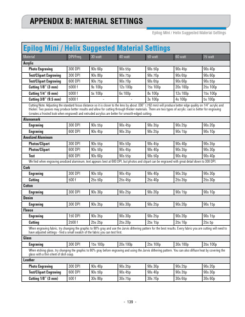
APPENDIX B: MATERIAL SETTINGS
Epilog Mini / Helix Suggested Material Settings
Epilog Mini / Helix Suggested Material Settings
Material
DPI/Freq. 30 watt
40 watt
- 140 -
Appendix B: Material Settings
Epilog Mini / Helix Suggested Material Settings • These are only suggestions: Every type of material will react differently with the laser, even from one plastic to the next. But don’t feel that
SWATCH-店铺操作规范

• •
• (注意事项:) • a.发生丢失不得隐瞒不报,如私自解决一经发现将严肃处理。 • b.向顾客展示产品前后过程中,随时关注产品位置。在收回产品时,更要严 格检查表盒内实际产品是否存在,随时保持货品安全意识。
残损
• 残损品:店内货品发现残损情况不能正常销售的(表镜裂、表镜深度 划痕无法抛光、表头磕伤、特殊包装缺少或损坏、缺少配件未通报主 管的),当班人员按零售价均分赔偿,不能分清责任的现有全店人员 按零售价均分赔偿。 • 店内货品缺少电池,当班人员按电池零售价的10倍赔偿,不能分清责 任的现有全店人员按零售价10倍均分赔偿。 • 店内货品有电池但没有电量,又未通知主管的,当班人员按电池零售 价赔偿,不能分清责任的现有全店人员按电池零售价均分赔偿。 • 调回公司的货品必须做好清洁,保证调回货品、保单、说明书、表盒 后的型号价签及表盒完整干净,表膜只留原表镜的。未作完整的清洁, 调回人员按10元/只处罚。
试戴
• • • • • 1.主动为客人试戴,一次最多取出3支手表给客人观看 2.货品贵重要亲自为客人佩带、摘除,如未按照执行,发生掉落或其他问题 自行承担 3.带手套将产品清洁后放回货柜陈列,避免留下指印影响产品美观及损坏 4.带包装货品观看后收回时,注意货品安全,仔细核对货品是否损坏 5.高价位货品观看、试戴时,店长或当班同事需要在销售过程中予以协助,以保 证销售成交及货品安全. (注意事项:) 在销售过程中,每笔销售专人负责,避免因交接不当引起丢失
陈列货品保养
• • • 1.表膜美观包好,一物一签,调好当地时间保持一致 2.新货到店,当天陈列出样 3.陈列产品9成新时与库存进行替换
• • • • •
(注意事项:) a.货品必须在九成新时与库存替换,避免产品过于老旧,影响销售 b.出样时,表膜要包装美观,齐全,不可包一半露一半,产生两种颜色效果 c.首饰\FF产品同上 d. 产品在陈列后,特别包装不得损坏丢失,否则照价赔偿
swatchツール导入とテスト手顺书
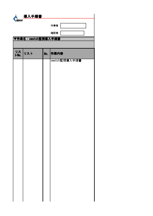
swatch監視導入手順書リス作業者確認者▼作業名:swatch監視導入手順書swatch監視導入手順書作業内容トNo.リストNo.緊急状況連絡員緊急状況連絡方式[root@TEST01 ~]# cd /download/[root@TEST01 download]# lscheck_traffic.sh nagios-3.4.3.tar.gz nagios-plugins-1.4.16.tar.gz nrpe-2.13.tar.gz p nagios nagios-plugins-1.4.16 nrpe-2.13 pnp4nagios-0.6.15 r swatch-3.2.3-7.el6.noarch.rpm[root@TEST01 download]# rpm -ivh swatch-3.2.3-7.el6.noarch.rpm警告: swatch-3.2.3-7.el6.noarch.rpm: ヘッダ V3 RSA/SHA256 Signature, key ID 0608b895: NOKEY エラー: 依存性の欠如:perl(Date::Parse) は swatch-3.2.3-7.el6.noarch に必要とされていますperl(Date::Calc) は swatch-3.2.3-7.el6.noarch に必要とされていますperl(Date::Manip) は swatch-3.2.3-7.el6.noarch に必要とされています「perl-Date-Calc」、「perl-TimeDate」、「perl-Date-Manip」をダウンロードして、/download/rpm[root@TEST01 rpm]# rpm -ivh perl-Date-Calc-6.3-2.3.noarch.rpm警告: perl-Date-Calc-6.3-2.3.noarch.rpm: ヘッダ V3 RSA/SHA256 Signature, key ID 0608b895: N エラー: 依存性の欠如:perl(Bit-Vector) は perl-Date-Calc-6.3-2.3.noarch に必要とされていますperl(Carp-Clan) は perl-Date-Calc-6.3-2.3.noarch に必要とされています[root@TEST01 rpm]# rpm -ivh perl-Date-Manip-6.14-0_15.el6.noarch.rpm警告: perl-Date-Manip-6.14-0_15.el6.noarch.rpm: ヘッダ V3 RSA/SHA256 Signature, key ID 0608エラー: 依存性の欠如:(atrpms) は perl-Date-Manip-6.14-0_15.el6.noarch に必要とされていますperl(YAML-Syck) は perl-Date-Manip-6.14-0_15.el6.noarch に必要とされています[root@TEST01 rpm]# rpm -ivh perl-TimeDate-1.20-1.el6.rfx.noarch.rpm必要なパッケージをダウンロードして、/download/rpm/にSCPする[root@TEST01 download]# cd /download/rpm/[root@TEST01 rpm]# lsgd-devel-2.0.35-11.el6.x86_64.rpm perl-Date-Calc-6.3-2.3.noarch.rpm perl-Bit-Vector-7.1-1.el6.rfx.x86_64.rpm perl-TimeDate-1.20-1.el6.rfx.noarch.rpm perl-Carp-Clan-6.04-1.el6.rfx.noarch.rpm perl-YAML-Syck-1.17-1.el6.rfx.x86_64.rpm php-devel-5.3.3-40.el6_6.x86_64.rpm rrdtool-devel-1.3.8-7.el6.x86_64.rprrdtool-perl-1.3.8-7.el6.x86_64.rpm perl-Date-Manip-6.14-0_15.el6.noarch.rpm atrpms-77-1.noarch.rpm[root@TEST01 rpm]# rpm -ivh perl-Carp-Clan-6.04-1.el6.rfx.noarch.rpm[root@TEST01 rpm]# rpm -ivh perl-Bit-Vector-7.1-1.el6.rfx.x86_64.rpm[root@TEST01 rpm]# rpm -ivh perl-Date-Calc-6.3-2.3.noarch.rpm[root@TEST01 rpm]# rpm -ivh perl-YAML-Syck-1.17-1.el6.rfx.x86_64.rpm[root@TEST01 rpm]# rpm -ivh atrpms-77-1.noarch.rpm[root@TEST01 rpm]# rpm -ivh perl-Date-Manip-6.14-0_15.el6.noarch.rpm[root@TEST01 rpm]# yum install perl-devel「df」ファイルを設定する[root@TEST01 ~]# vi /etc/swatch.conf(以下の内容を追加する)watchfor /SERVICE ALERT/iecho redmail=pbits-mbiz-alert-external@, subject=Have SEVICE ALERT,please chec throttle 01:00「nagios」のログを監視して、メールを送信できるかのをテストする[root@TEST01 ~]# /usr/local/sbin/swatch -c /etc/swatch.conf -t /usr/local/nagios/var/nagios [2] 17124[root@TEST01 ~]#*** swatch version 3.1.1 (pid:17124) started at 2015年 2月 9日 月曜日 13:23:53 JST[root@TEST01 ~]# ps -ef |grep swatchroot 17124 20319 0 13:23 pts/1 00:00:00 /usr/bin/perl/usr/local/bin/swatch -c /etc/swatch.conf -t /usr/local/nagios/var/nagios.logroot 17125 17124 0 13:23 pts/1 00:00:00 /usr/bin/perl /root/.swatch_script.17124 root 31226 20319 0 13:58 pts/1 00:00:00 grep swatch[root@TEST01 ~]#メールが受信かのを確認する[root@TEST01 ~]#vi /etc/rc.d/rc.local(以下の内容は末尾に追加する)/usr/local/sbin/swatch -c /etc/swatch.conf -t /usr/local/nagios/var/nagios.log &p4nagios-0.6.15 rpm□ID 0608b895: NOKEYして、/download/rpm/にSCPする□key ID 0608b895: NOKEY□ature, key ID 0608b895: NOKEY□□6.rfx.noarch.rpml6.rfx.x86_64.rpm64.rpm15.el6.noarch.rpm□□□□□□□□ALERT,please check;□/nagios/var/nagios.log & 3:23:53 JST□ch_script.17124□□。
AS x70i DUO 读卡器使用手册说明书
Reading DeviceAS x70i DUO/IRRLAS x70i DUO/IRIRAS x70i DUO/KEY Manual and operational descriptionManual and operational descriptionAS x70i DUO (all variants)Page 2 © SKIDATA AG, January 2004SKIDATA AG Technical DocumentationUntersbergstrasse 40A-5083 GartenauTelephone +43 6246 888-0,Telefax +43 6246 888-7Internet e-mail ****************Copyright© 2004 by SKIDATA AG. All rights reserved. All information in thefollowing document is protected by copyright law. No part of thisdocument may be reproduced without the written consent of SKI-DATA AG. SKIDATA AG reserves the right to make any changesof specification and other information in this document withoutfurther notice.Please noteDuring the compilation of this Technical Documentation, greatcare has been taken to ensure the accuracy of the informationcontained in it. However, despite our constant effort to ensure thehighest degree of accuracy and comprehensiveness possible,the information provided cannot be guaranteed to be absolutelyerror-free.TrademarksThis documentation may contain representations of registered product or service trademarks owned by SKIDATA AG or thirdparties, as well as references to proprietary know-how protectedby copyright laws or other legal provisions. In any case the intel-lectual property rights remain exclusively with their respectiveowners.Declaration of ConformityThe AS x70i DUO product family has been developed, designedand manufactured in accordance with the following EU directive:R&TTE (99/5/EC)0408Version January 2004AS x70i DUO (all variants) Manual and operational descriptionNote:In the US only the variants AS x70i DUO/KEY and AS x70iDUO/IRRL are sold and operated. Hence, only these two variantsare FCC certified and the FCC rules are subject to these variantsonly.FCC 15.19:This device complies with Part 15 of the FCC Rules. Operationis subject to the following two conditions: (1) this device may notcause harmful interference, and (2) this device must accept anyinterference received, including interference that may cause un-desired operation.FCC 15.21:IMPORTANT: Any changes to or modifications of AS x70i DUO(all variants) unless expressly approved by SKIDATA AG, mayvoid the user's authority to operate this device.© SKIDATA AG, January 2004 Page 3Manual and operational description AS x70i DUO (all variants)AS x70i DUO (all Variants) 1Document Management – Version TableTab. 1: Document Version Table for Installation & Maintenance Instructions1 AS x70i DUO (all Variants) 16 1.0 08-01-2004Page 4 © SKIDATA AG, January 2004AS x70i DUO (all variants) 11AS x70i DUO/IRRLAS x70i DUO/IRIRAS x70i DUO/KEYVersion 1.016 pagesCopyright 2004 by SKIDATA AG1 AS x70i DUO (all variants) 1.1Contents1.1 Contents1.1Contents 21.2Safety Instructions 31.2.1General safety instructions and warnings 31.2.1.1Notes concerning wearers of medical devicesand implants 31.2.1.2Danger of injury by rotating parts 51.2.2Safety instructions – Turnstile DKZ 350 51.2.2.1Operating hazards of Turnstile 350 61.2.2.2Safety precautions during maintenance 61.2.2.3Obligation of the operator to meet safety requirements61.2.2.4Safety and warning devices 71.2.2.5Training of operating personnel 71.2.2.6Appropriate use 71.2.2.7Warranty and liability 71.2.3Electromagnetic Compatibility (EMC) 81.3Reading device AS x70i DUO 91.3.1Replacing the reader mechanismassembly 91.3.1.1Removing the protective hood of the readermechanism assembly 111.3.1.2Removing the protective hood of the readermechanism assembly (old version) 121.3.2Cable connections inside the reader 131.3.3Replacing traffic light lamps 141.3.4Cleaning the barcode scanner 151.3.5Replacing the Compact Flash card 16 Page 2 © SKIDATA AG, Version 1.0AS x70i DUO (all variants)1 Safety Instructions1.2© SKIDATA AG, Version 1.0 Page 31.2 Safety InstructionsAll components of the AS x70i DUO (all variants) have been sub-jected to a series of safety tests. Any remaining dangers that may exist are pointed out during system training courses as well as in this manual and the installation guide.1.2.1 General safety instructions and warnings System devices may be used exclusively for their intendedpurpose, as specified by the manufacturer.Unauthorised modifications of the devices as well as the useof replacement parts and/or add-on devices not approved by the manufacturer may increase the risk of electric shock or cause other serious bodily harm and will void the manufac-turer’s warranty.The setup, installation, maintenance and configuration of thedevices is limited to certified electricians with special training in accident prevention.The executive or commissioned technician, or the projectmanager, is responsible for ensuring that the devices are in-stalled and configured in compliance with local technical re-quirements as well as other applicable local rules andregulations. This applies particularly to cable dimensions, protection against risks, earth connection, deactivation, dis-connection, insulation testing, and overcurrent protection.1.2.1.1 Notes concerning wearers of medicaldevices and implantsSKIDATA™ devices are CE certified and therefore comply with all applicable health and safety guidelines.Like all handsfree scanners and contactless RF devices (e.g., ski lift access control devices), SKIDATA™ handsfree products used for contactless processing (reading and coding) of chip-based data carriers inevitably generate an electromagnetic field in close proximity to the antenna. To ensure the greatest possible safety for wearers of active medical implants (e.g. pacemakers), RF-based SKIDATA™ devices have been subjected to further tests by an accredited testing body.The test results indicate that SKIDATA™ devices, when used as directed, are perfectly safe for pacemaker wearers passing a handsfree ski lift access gate (note that this does not necessarily apply to devices by other manufacturers). However, to safeguard the health of those concerned (e.g. pacemaker wearers) and to comply with statutory warning obligations, people wearing medi-cal devices (e.g. pacemakers) should be required to adhere to the general recommendations for the use of electromagnetic de-vices in addition to the following guidelines:1AS x70i DUO (all variants)1.2Safety InstructionsPage 4 © SKIDATA AG, Version 1.0Persons affected by these guidelines (e.g. pacemaker wear-ers) are not allowed to place keycards or other contactless (electronic) access control data carriers next to the implant when passing an access device.When passing through an access gate, a minimum distanceof 30 cm should be kept between the antenna and the implant (to ensure this minimum distance, the use of a Swatch Access watch or Gore [s-key] gloves is recommended).Wearers of medical implants such as pacemakers shouldavoid leaning against an antenna unit.For wearers of medical implants such as pacemakers, thetime of exposure to the RF scanning signal should be as short as possible when passing through the gate at normal speed; when queuing, they should stand at an appropriate distance from RF-based devices.Persons experiencing problems such as dizziness or nauseawhen passing an antenna should leave the scanning range of the device immediately.Antennas must bear a warning label or prohibit label (shown in figures below), which must be readily visible to wearers of medi-cal devices. In addition, a warning sign with the above-mentioned safety guidelines should be placed at every point of initial access (e.g. cash desks).Also, lift staff should receive appropriate instructions to be able to provide information and assistance if and when required.Fig. 1:Warning labelAS x70i DUO (all variants)1 Safety Instructions1.2© SKIDATA AG, Version 1.0 Page 51.2.1.2 Danger of injury by rotating partsOperators should be aware of the danger of bruising by the rotat-ing worm drive inside Turnstile DKZ 350. DANGER OF INJURY – Never touch these parts while the unit is in operation.1.2.2 Safety instructions – Turnstile DKZ 350The DKZ 350 Turnstile unit is a machine as defined by EU Direc-tive ‘98/37/EC Machinery’. This directive sets forth the safety re-quirements to be met by both the manufacturer and the operator of the turnstile unit.The DKZ 350 Turnstile Unit has been designed and manufac-tured in accordance with the most advanced technological stan-dards and in full compliance with acknowledged technical rules and regulations. However, the possibility of impairment to mate-rial assets or injury to users or operators cannot be ruled out completely. Remaining dangers are pointed out in this manual as well as during system training courses.The turnstile unit may be used onlyfor its intended purpose (see below)if it is operationally safeAny faults which might impair the operating safety of the unitmust be removed without delay.To ensure a safe and fault-free operation of the DKZ 350Turnstile, operators must be familiar with the basic instruc-tions and regulations regarding operating safety.Fig. 2:Prohibition label1AS x70i DUO (all variants)1.2Safety InstructionsPage 6 © SKIDATA AG, Version 1.0 These instructions, particularly the safety instructions, must befollowed by all operators responsible for maintaining and con-figuring the unit.Applicable local rules and regulations for accident preventionmust be adhered to at all times.1.2.2.1 Operating hazards of Turnstile 350 There is a theoretical risk of small children being hit in theback of the head by the automatically controlled turnstile bars. This danger can be virtually eliminated by deactivating the light sensor.(Note: Automatic control of the turnstile bars facilitates the proc-ess of clearing the gate, as it requires no force on the part of the user.)In model DKZ 350 S1 with only one bar, the automatic control function cannot be deactivated. The use of model DKZ 350 S1 turnstiles therefore requires additional measures to minimise the risk of injury to small children. Such measures might include multi-lingual warning messages, pictograms, etc, to caution ac-companying adults against the danger.1.2.2.2 Safety precautions during maintenance Danger of injury to fingers by rotating worm drive when gear casing is open.To avoid injury, turn off the turnstile unit during maintenanceor avoid reaching into the gear casing while the turnstile bars are in motion.When maintenance work is performed on the turnstile unit, theaccess area must be cordoned off for the duration.1.2.2.3 Obligation of the operator to meet safetyrequirements According to EU Directive ‘98/37/EC Machinery’ operator is un-der obligationto provide adequate means for securing the danger areaaround the turnstile unit and to caution against remaining safety hazards;to restrict handling of the turnstile unit to authorised personnelwho have been properly instructed in the operation of the turn-stile and who have been advised of possible dangers in train-ing courses provided by SKIDATA AG and the study of theSafety Instructions 1.2 safety regulations and instructions contained in this documen-tation;to ensure safety around the access area;to ensure that the required system maintenance tasks are car-ried out regularly.1.2.2.4 Safety and warning devicesThe protection and warning devices to be installed around the danger area of the turnstile are to be kept in good condition. Warning signs and information posters are to be kept in read-able condition.1.2.2.5 Training of operating personnel Configuration and maintenance of the DKZ 350 Turnstile Unit is restricted to personnel with proper training and experience.1.2.2.6 Appropriate useThe DKZ 350 Turnstile Unit is intended exclusively for controlling passage through personnel access and exit points. The unit can be operated either manually or automatically in combination with a control device for verifying access authorisations. Users can clear the DKZ 350 Turnstile with their skis on.Any use not described in this documentation is considered as be-ing inappropriate. SKIDATA AG will under no circumstances as-sume liability for any damage arising from such inappropriate use of the turnstile unit.1.2.2.7 Warranty and liabilityIn the event of damage to person or property, all warranty and li-ability claims shall be excluded, should this damage be attribut-able to one or more of the following:Inappropriate use of the DKZ 350 Turnstile UnitImproper installation of the turnstile or any part thereofInadequate or missing warning facilities and/or safety devices inside the danger area around the DKZ 350 Turnstile UnitIrregular or insufficient maintenanceUse of material not approved by SKIDATA AGInsufficient structural renovationInsufficient training of operating personnelUnauthorised constructional or technical modifications of the DKZ 350 Turnstile Unit, particularly modifications of the turn-stile drum or its support fixture1.2Safety InstructionsDisaster situations brought about by impact of foreign bodiesor acts of God.1.2.3 Electromagnetic Compatibility (EMC)All integral devices of Access Control System 350 have been de-veloped, designed and manufactured in full compliance with EUDirective ‘89/336/EWG Electromagnetic Compatibility’.Compliance with EU Directive ‘89/336/EEC ElectromagneticCompatibility’ must be maintained during operation. This requiresthatSpecified max. network connection distances are not ex-ceededNetwork connections are properly installed and maintainedNetwork terminals are connected as specified, and star dis-tributor links are properly installed and maintainedNetwork cable screens are properly installed and maintainedRecommendation: connect each AS x70i DUO to the potentialequalisation panel by way of a 16 mm2 earth leadAll system devices and facility installations subject to EMCregulations are inspected regularly and repaired if required.Reading device AS x70i DUO 1.31.3 Reading device AS x70i DUO1.3.1 Replacing the reader mechanism assemblyRemoving the reader mechanism assemblyUsing a 4 mm Allen wrench, unfasten and remove the fasten-ing screw (Allen screw) at the rear of the reader.Press in the locking screw at the rear.Carefully tilt the top section towards the front, as indicated bythe arrow in the illustration below.Disconnect the cables leading into the interior of the casing(cables for heater, signal light control, etc.).Remove the reader top section by lifting it up and taking it outof its housing.Fig. 3:Replacing the reader top section1.3Reading device AS x70i DUOReinstalling the reader mechanism assemblyPlace the top section into the groove at the bottom of the frontopening of the housing.Reconnect all cables, making sure they are completely insidethe housing to avoid them being pinched.Push the mechanism assembly back into the housing.Fasten the Allen screw at the rear of the reader using a 4 mmAllen screw.Fig. 4:Opening the reader top sectionReading device AS x70i DUO 1.31.3.1.1 Removing the protective hood of the readermechanism assemblyPress against the locking tab at the base of the hood (see il-lustration below: (2)).Remove the hood, bottom first (see illustration below: (2)).Fig. 5:Removing the protective hood ofthe reader mechanism assembly1.3Reading device AS x70i DUO1.3.1.2 Removing the protective hood of the readermechanism assembly (old version)Using a 2 mm Allen wrench, unfasten and remove the four Al-len screws that hold the hood in place.Remove the hood.Fig. 6:Removing the protective hood ofthe reader mechanism assemblyReading device AS x70i DUO 1.3connections inside the reader1.3.2 CableFig. 7: Cable connections inside the reader1.3Reading device AS x70i DUO1.3.3 Replacing traffic light lampsIn the current production of the AS x70i DUO, LEDs are used forthe traffic light. These LED lamps are maintenance free. Olderversions of the AS x70i DUO use festoon bulbs. The replacing ofthe bulbs is described below.To ensure water tightness after replacing the lamp(s), the screwwashers should be replaced with O-rings.SKIDATA™ article code for O-rings : AS 350 ZA, No. 535200020Make sure the lamps are positioned tightly in the lamp holder(press the contact plates of the lamp holder inwards as nec-essary)When re-assembling the traffic light, ensure precise position-ing of the sealing washers.Be careful not to fasten the screws too tightly.Fig. 8:Replacing traffic light lampsReading device AS x70i DUO 1.3 The red/green traffic light is illuminated by special incandescent lamps. Spares are available from your SKIDATA™ service pro-vider or from commercial hardware stores.Technical specifications:Festoon bulb, 24 V / 5 W, length: 37.5 mmItem code for red lamp: 470030050Item code for green lamp: 4700300521.3.4 Cleaning the barcode scannerDirt accumulating on the optical system of the reader may cause a reduction in recognition rate and ticket reading speed. This can be prevented by cleaning the lenses of the barcode scanner at regular intervals (at least once every four weeks; more frequently if the device is exposed to conditions that cause heavy soiling). The lenses must also be cleaned in case of reading errors.Note that the barcode scanner module of the AS x70i DUO can-not be de-installed. As a result, the scanner modules may only be cleaned by trained staff.1.3Reading device AS x70i DUOCompact Flash cardthe1.3.5 ReplacingTo replace the compact flash card, proceed as follows:Push the card ejection button (see illustration below).Take out the card.Insert the new card (ensure correct alignment).Fig. 9:Replacing the Compact Flashcard。
卡西欧wvA3100石英表说明书

卡西欧wvA3100石英表说明书卡西欧wvA3100石英表说明书:方法/步骤分步阅读将卡西欧石英表解开,戴在手上不容易调节,可以看到右侧有调节旋钮。
有些石英表有日期,有些没有,要仔细看清楚,有些石英表上面内盘不仅仅有日期还有星期、整点指示等。
确认上面的日期对不对,而且基本上两个月就要调节一次,因为上面一般设置为31天,有些月份只有30天,二月28/29天,这些都要调节,不然日期就会不准。
用手按压住调节旋钮,轻轻往外侧拉,一般有两个档位,一个第一个档位就是调节日期的,第二个档位调节时间,拉到第二个档位时间就停止了,所以还是比较好认。
缓慢向外拉,听到清脆的咔的一声,即为拉出第一个档位,然后逆时针调节,可以看到日期逐渐增加,反向无动作。
调节到准确的日期,如果日期超过,只能重新转到31再转到新的日期,调节无误后记得要旋钮按压回去即可。
扩展:在佩戴卡西欧手表之前,大家一定要先仔细的阅读一下卡西欧手表说明书,因为只有掌握了卡西欧手表说明书上面的内容,大家才能够正确的使用手表。
在卡西欧手表说明书上会向我们讲解一些相关的知识,以及后续的保养问题。
比如说在卡西欧手表说明书上就告诉了我们如何去调时间,首先可以长按左上按键10秒左右,然后再切换至左下的按钮。
按右上和右下来调节时间,完成后按一下左上确定就可以了。
当然卡西欧手表说明书上也会告诉我们关于手表的各个按键的意义,每一个按键都有它指定的功能,大家切记千万不要胡乱的按健。
而且在卡西欧手表说明书上还会告诉我们使用时的一些规范性问题,比如说如果大家平时没有办法天天去佩戴手表,如果是长期不佩戴的话,也应该定期的上线,然后使机芯片转动,如果是石英手表的话,因为它的使用寿命一般是在1~2年,所以电池应该定期的更换。
这些使用规范性的问题都会在说明书上提到。
一般来说卡西欧手表说明书分为两种类型,一种是纸质的,随着卡西欧手表盒子一起给到大家的手中。
另外一种是电子版本的,因为现在大家都是在网络上操作,所以也会给大家一个电子版本的说明书。
- 1、下载文档前请自行甄别文档内容的完整性,平台不提供额外的编辑、内容补充、找答案等附加服务。
- 2、"仅部分预览"的文档,不可在线预览部分如存在完整性等问题,可反馈申请退款(可完整预览的文档不适用该条件!)。
- 3、如文档侵犯您的权益,请联系客服反馈,我们会尽快为您处理(人工客服工作时间:9:00-18:30)。
Hands come together at 12 o‘clock and start to rotate at least on full turn.
IMPORTANT: If hands are not exactly at 12 o‘clock, they have to be readjusted.
~4 secs. Hands stop by accident and show the result of your game for some seconds... ...then, hands turn back to time.
5 /6
USER MANUAL
SCUBA FUNCTION: ELAPSED TIME
USER MANUAL
TIME SETTING Standard
SET
ABC
GO
ABC
Lorem ipsum TOUCH / FUN
Minute Hour
SET
1. 2.
GO
A: Normal position of the crown C: Position for setting the time
SET
READ
Using the adjustment ring For setting the start time and duration of an activity, line up the marker on the adjustment ring with the minute hand. Timing starts at the time indicated by the marker. The elapsed time is indicated by the minute hand pointing the number on the adjustment ring.
ALARM ON/OFF
o n
...CHANGE ON/OFF
o on
SHOW LAST ALARM
1. 2.
...SET NEW ALARM
1. 2.
GO
Switch alarm on/off and set alarm time Press crown and hands go to actual mode on or off. Press crown again to change mode.
WARNING NOTE
IMPORTANT: After being submerged in salt water, the Scuba 200 Chrono should always be rinsed with fresh water. CAUTION: The Irony Scuba 200 Chrono is not a professional diving watch.
1 /6
USER MANUAL
DATE OR DAY SETTING STANDARD
SET
ABC
GO
ABC
To set the date, pull the crown out to position B, and turn anticlockwise. To set the day, turn the crown in a clockwise direction. After resetting has been completed, press the crown back to position A.
If hands are not exactly at 12 o’clock, pull crown to position 2. Turn clockwise to readjust hour hand. Turn counter clockwise to readjust minute hand. Push crown back and hands turn back to show time.
4 /6
USER MANUAL
ALARM DEMO
TOUCH GAME
2 sec.
Press crown for 2 seconds to start alarm demo. To stop, press crown again.
Touch your Swatch.
IMPORTANT: When the hands do not show correctly ONOFF (alarm mode), the Touch Alarm must be adjusted (e.g. after battery change or a hard knock).
3 /6
USER MANUAL
TOUCH ALARM
SHOW ALARM TIME
~4 secs. Touch your Swatch. Hands move to show alarm time for approx. 4 seconds.
STOP ALARM
Touch your Swatch to stop alarm.
6 /6
Pull crown to position 1 and the hands go to the last alarm time. To set a new alarm time, turn crown (turn slowly = minutes, turn quickly = hours). Then push crown back and hands turn back to time and alarm mode will be “on”.
To set the time, pull the crown out to position C and turn clockwise or anticlockwise. After resetting has been completed, press the crown back to position A.
READJUSTMENT TOUCH / FUN
TEST / OK
5 sec.
ADJUST HAND/+HOUR
1. 2.
Go to 12
pull within 5 sec.
ADJUST HAND/+MINUTES
1. 2.
Go to 12
GO
Push crown for 5 seconds. If both hands go to 12 o’clock, test is ok. Push crown again and hands go back to time.
To set the time, pull the crown to position 2. Turn slowly to correct minutes. Turn quickly to correct hours. After resetting has been completed, push the crown back.
2 /6
USER MANUAL
LOOMI FUNCTION: DISPLAY TOUCH LOOMI
TOUCH YOUR SWATCH
LOOMI ON
~4 secs.
LOOMI
LIGHT FUNCTION
Push
POP
POP-IN
POP-OUT
POP ON CLOTHES
Note: Wear your Swatch simply with its band or try „popping“ it directly onto your clothes.