旋转阀说明书
TF230-S旋转式安全控制阀说明书
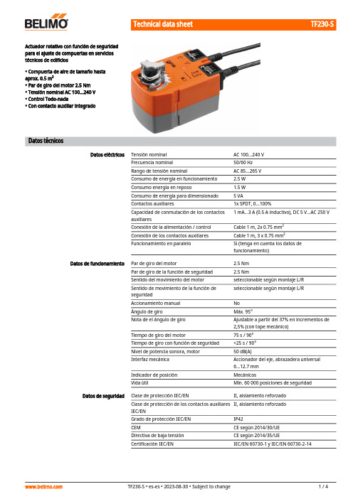
TF230-SActuador rotativo con función de seguridadpara el ajuste de compuertas en serviciostécnicos de edificios• Compuerta de aire de tamaño hastaaprox. 0.5 m²• Par de giro del motor 2.5 Nm• Tensión nominal AC 100...240 V• Control Todo-nada• Con contacto auxiliar integradoDatos técnicosDatos eléctricos Tensión nominal AC 100...240 VFrecuencia nominal50/60 HzRango de tensión nominal AC 85...265 VConsumo de energía en funcionamiento 2.5 WConsumo energía en reposo 1.5 WConsumo de energía para dimensionado 5 VAContactos auxiliares1x SPDT, 0...100%Capacidad de conmutación de los contactos1 mA...3 A (0.5 A inductivo), DC 5 V...AC 250 VauxiliaresConexión de la alimentación / control Cable 1 m, 2x 0.75 mm²Conexión de los contactos auxiliares Cable 1 m, 3 x 0.75 mm²Funcionamiento en paralelo Si (tenga en cuenta los datos defuncionamiento)Datos de funcionamiento Par de giro del motor 2.5 NmPar de giro de la función de seguridad 2.5 NmSentido del movimiento del motor seleccionable según montaje L/Rseleccionable según montaje L/RSentido de movimiento de la función deseguridadAccionamiento manual NoÁngulo de giro Máx. 95°Nota de el ángulo de giro Ajustable a partir del 37% en incrementos de2,5% (con tope mecánico)Tiempo de giro del motor75 s / 90°Tiempo de giro con función de seguridad<25 s / 90°Nivel de potencia sonora, motor50 dB(A)Interfaz mecánica Accionador del eje, abrazadera universal6...12.7 mmIndicador de posición MecánicosVida útil Mín. 60 000 posiciones de seguridadDatos de seguridad Clase de protección IEC/EN II, aislamiento reforzadoII, aislamiento reforzadoClase de protección de los contactos auxiliaresIEC/ENGrado de protección IEC/EN IP42CEM CE según 2014/30/UEDirectiva de baja tensión CE según 2014/35/UECertificación IEC/EN IEC/EN 60730-1 y IEC/EN 60730-2-14TF230-SDatos de seguridadPrueba de higieneDe conformidad con VDI 6022 parte 1 / SWKI VA 104-01, limpiable y desinfectable, bajas emisiones Tipo de acciónTipo 1.AA.B Categoría de sobretensiónIII Tensión de resistencia a los impulsos4 kVTensión de resistencia a los impulsos, contactos auxiliares 4 kV Grado de polución 3Humedad ambiente Máx. 95% de RH, sin condensación Temperatura ambiente-30...50°C [-22...122°F]Temperatura de almacenamiento -40...80°C [-40...176°F]Mantenimientosin mantenimiento PesoPeso 0.66 kgDatos técnicos•••••••Notas de seguridadEste dispositivo ha sido diseñado para su uso en sistemas estacionarios de calefacción,ventilación y aire acondicionado y no se debe utilizar fuera del campo específico de aplicación, especialmente en aviones o en cualquier otro tipo de transporte aéreo.Aplicación en exterior: sólo es posible en el caso de que el dispositivo no esté expuestodirectamente a agua (de mar), nieve, hielo, radiación solar o gases nocivos y que se asegure que las condiciones ambientales se mantienen en todo momento dentro de los umbrales de acuerdo con la ficha de datos.Precaución: alimentaciónSólo especialistas autorizados deben realizar la instalación. Durante la instalación, deberán cumplirse todas las regulaciones de instalación legales o institucionales que correspondan.El dispositivo sólo se puede abrir en el centro del fabricante. No contiene piezas que el usuario pueda reemplazar o reparar.No se deben retirar los cables del dispositivo.El dispositivo contiene componentes eléctricos y electrónicos y no se puede desechar con los residuos domésticos. Deben tenerse en cuenta todas las normas y requerimientos locales vigentes.Modo de funcionamientoMontaje directo y sencillo Ángulo de giro ajustable Alta fiabilidad funcional Señalización flexibleCaracterísticas del productoEl actuador mueve la compuerta hasta la posición de funcionamiento al mismo tiempo que tensa el muelle de retorno. Cuando se interrumpe la alimentación, la energía del muelle vuelve a colocar la compuerta en la posición de seguridad.Montaje directo y sencillo en el eje de la compuerta con una abrazadera universal, suministrada con un dispositivo antirrotación para impedir que el actuador gire.Ángulo de giro ajustable mediante topes mecánicos.El actuador se encuentra protegido contra sobrecargas, no necesita ningún contacto limitador y se detiene automáticamente cuando alcanza el final de carrera.Con contacto auxiliar ajustable (de 0...100%)AccesoriosAccesorios mecánicosDescripciónModelo Palanca para actuadorAH-TF Extensión del eje 170 mm ø10 mm para eje de la compuerta ø6...16 mm AV6-20Rótula Adecuado para palanca de transmisión de compuerta KH8 / KH10KG10ATF230-SDescripciónModelo Rótula Adecuado para palanca de transmisión de compuerta KH8KG8Palanca de transmisión Ancho de la ranura 8.2 mm, rango de nuez ø10...18 mm KH8Kit de sujeciónSB-TF Limitador de ángulo de giro, con tope final ZDB-TF Adaptador para ejes cuadrados 8x8 mmZF8-TF Kit de montaje para acoplamiento para montaje plano o lateral ZG-TF1Mecanismo antirrotación 180 mm, Multipack 20 uds.Z-ARS180AccesoriosColores de los hilos:1 = azul 2 = marrón S1 = violeta S2 = rojo S3 = blancoInstalación eléctricaPrecaución: alimentaciónEs posible realizar una conexión en paralelo de otros actuadores. Respete los datos de funcionamiento.Esquema de conexionado AC 230 V, todo-nadaContacto auxiliarTF230-SDimensionesLongitud del ejeMin. 84Min. 20Rango de nuez。
偏心旋转阀

3. 气动偏心旋转调节阀的使用环境温度为-40~60℃,以免橡胶膜片和密封件 在高温时易老化和在低温时易变脆。
4. 气动偏心旋转调节阀定位器的气源压力不应超过铭牌上所标定的压力值。 5. 气动偏心旋转调节阀在动作前,首先应检查手轮是否在空档位置,然后利 用锁紧螺母固定手轮。 6. 气动偏心旋转调节阀的机械运动连接处应定期加注二硫化钼润滑剂或润滑 脂。 7. 气动偏心旋转调节阀应定期进行维护保养。维护保养时应重点对阀芯、阀 座、填料和执行机构中的膜片等零件进行检查,如有损坏,应及时修复或更换。
7.03
-
-
-
135
1.40 1.97 1.27
2.67
4.22
-
-
-
80
81
2.25
2.95
1.90
4.08
6.54
-
-
-
54
3.23
4.50
2.81
6.12
7.03
-
-
-
230
0.70
0.98
0.63
1.40
2.25
3.10
3.94
4.22
100
138
1.12
1.55
0.98
2.10
3.45
4.71
850
流关L 0.48 - 0.17 0.41 0.62 0.62 0.62 - - - - -
70
0.11
流开, 流关
-
- 1.52
-
-
-
-
-
-
-
-
-
TSV 四线三道的旋转阀门说明书

TSV30043TSV30043TSV30042TSV30043TSV30042RP2-47P2-484/2, 4/3 Way Rotary ValveSpecificationsSymbolHow to orderFlow chartFeatures1. Simply operating.2. Large flow rate.3. High safety.4. Light weight.5. 4 kinds of installation.6. Twist lock is optional for safety operation.:4/3 Way :4/2 Way02 02 :1/4"03 :3/8"04 :1/2"Port sizeN:G N :NPT R :RcBlank ThreadBC P B Blank Valve type:Standard:Ports on bottom :With twist lock:With panel mountingMemo...w w wt.wm.soh c .a o k P2-49P2-50TSV4/2, 4/3 Way Rotary ValveSeriesExplosionOperating steps for twist lock1. P ush the button of lock down.2. T urn lever to the left or right.3. R elease your hand to let the button of lock bound back.4. P lease do not turn lever when the button of lock bound back.TSV8652-MTSV8652-SM FM02 01 :1/8"TSV8652N N :NPT R :RcFS02 :1/4"03 :3/8"R R04 :1/2"5/2 Way Hand Control ValveSpecificationsSymbolHow to orderFeaturesDimensionsExplosion1. Easy operation.2. Large flow rate.3. Suitable for vacuum operation.4. Available for panel mounting.5. Mounting bracket as optional accessory.6. TSV8652R-01/02 for manifold assembly.5/2 Way Port sizeBlank Blank ManifoldActing Thread Mounting bracket:Standard:Manifold type (for 1/8",1/4" port only):Spring return :Detent Blank :W/O bracket(For 1/8",1/4" port only):W/I mounting bracket :G P2-52P2-51P2-54MM02 TSV8753N:GN :NPT R :RcS02 :1/4"03 04 :3/8":1/2"SXMXP2-535/3 Way Hand Control ValveSymbolFeaturesHow to orderSpecificationsFlow chart5/3 WayPort sizeThreadActingBlank :Spring return :Detent :Exhaust center, Spring return :Exhaust center, Detent 1. Easy operation.2. Large flow rate.3. Suitable for vacuum operation.4. Mounting bracket as optional accessory.TSV8753-MTSV8753-SXTSV8753-STSV8753-MX。
AT Controls 手动和自动旋转阀门文档说明书
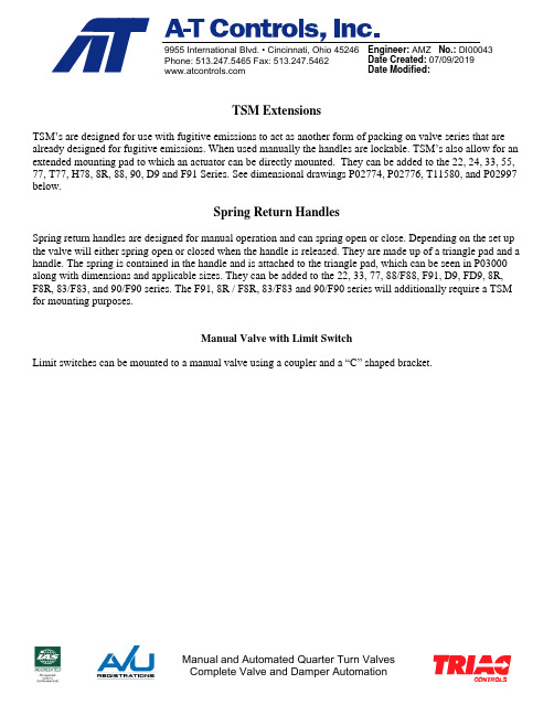
9955 International Blvd. • Cincinnati, Ohio 45246 Phone: 513.247.5465 Fax: 513.247.5462Engineer: AMZ No.: DI00043Date Created: 07/09/2019 Date Modified: TSM ExtensionsTSM’s are designed for use with fugitive emissions to act as another form of packing on valve series that are already designed for fugitive emissions. When used manually the handles are lockable. TSM’s also allow for an extended mounting pad to which an actuator can be directly mounted. They can be added to the 22, 24, 33, 55, 77, T77, H78, 8R, 88, 90, D9 and F91 Series. See dimensional drawings P02774, P02776, T11580, and P02997 below.Spring Return HandlesSpring return handles are designed for manual operation and can spring open or close. Depending on the set up the valve will either spring open or closed when the handle is released. They are made up of a triangle pad and a handle. The spring is contained in the handle and is attached to the triangle pad, which can be seen in P03000 along with dimensions and applicable sizes. They can be added to the 22, 33, 77, 88/F88, F91, D9, FD9, 8R, F8R, 83/F83, and 90/F90 series. The F91, 8R / F8R, 83/F83 and 90/F90 series will additionally require a TSM for mounting purposes.Manual Valve with Limit SwitchLimit switches can be mounted to a manual valve using a coupler and a “C” shaped bracket.MATERIALDATECHECKED BY DESCRIPTION9955 INTERNATIONAL BLVD.CINCINNATI, OHIO 45246PHONE: (513) 247-5465FAX: (513) 247-5462DRAWN BY DATEAMZSpring Return Handle Dimensional Drawing07/09/19DO NOT SCALE DRAWINGRELEASED BY CMB07/09/19DATECMB07/09/19VALVES, ACTUATORS, AND AUTOMATION CONTROLS。
旋转阀 国标
旋转阀国标
国标旋转阀说明书
一、概述
国标旋转阀是一种广泛应用于工业领域的阀门,其设计符合国家相关标准,具有高效、稳定、安全的特点。
该阀门通过旋转阀杆实现对流体介质的控制,可用于流体输送、控制和调节等场合。
二、产品特点
结构紧凑,体积小,易于安装和维护。
密封性能好,能够有效地防止介质泄漏。
操作简便,可以通过手动或电动方式进行操作。
适应性强,可用于各种不同的流体介质和工况条件。
三、工作原理
国标旋转阀的工作原理是通过旋转阀杆来控制阀口的开启和关闭。
当旋转阀杆时,阀口会随之转动,从而实现对流体介质的开关和控制。
根据不同的工况需求,可以选择不同的旋转角度来调节流量和压力等参数。
四、使用注意事项
在使用前应检查阀门的外观和密封性能,确保无损坏和泄漏现象。
根据实际需求选择合适的阀门型号和规格,并按照安装说明进行安装。
在操作过程中应避免过载或超压,以免损坏阀门和管道系统。
定期对阀门进行检查和维护,确保其正常运转和延长使用寿命。
五、常见问题及解决方案
阀门无法正常开启或关闭:可能是由于电动执行机构出现故障或电源连接问题所导致。
应检查执行机构和电源连接是否正常工作。
流体介质泄漏:可能是由于密封垫片老化或损坏所导致。
应更换密封垫片并重新调整阀门。
阀门旋转不灵活:可能是由于长期未使用或润滑不足所导致。
应定期对阀门进行润滑和维护。
AT Controls 手动和自动旋转阀门产品说明说明书

Hydrogen Peroxide ServiceHydrogen Peroxide is a colorless liquid that can be used for things such as disinfection and bleaching. Handled correctly, Hydrogen Peroxide can be safe. Handled incorrectly, however, it can be explosive and dangerous.A very clean and safe system is required for Hydrogen Peroxide service because of the dangers of this molecule. With this in mind, careful selection of materials of construction and makeup of Hydrogen Peroxide service valves is imperative. It is also important to know whether the system will have diluted concentrations of Hydrogen Peroxide (less than 50%) or higher concentrations (greater than 50%), and the temperature of the application.Vented BallHydrogen Peroxide is prone to decomposition into water and oxygen. This decomposition can increase pressure, even sometimes rapidly, in the enclosed cavity of the valve. A table showing the amounts of these decomposition products is shown on the next page. A-T Controls provides a means of relieving this pressure by venting the ball in the upstream direction. This limits the valve to one direction flow and an arrow on the valve shows which direction the valve should be installed. A vented, upstream ball is required for Hydrogen Peroxide service.Preparation, Cleaning, and Lubrication Valves used for Hydrogen Peroxide service are required to be passivated according to ASTM A380/A380M and ASTM A967/A967M before going into service. A-T Controls valves meet these requirements. An inert lubricant such as a fluorinated product is required for the construction of the valves. A-T Controls thoroughly cleans all valve parts and lubricates the O-ring with a compatible lubricant. The valves are vacuum packed with desiccant and marked as cleaned for Hydrogen Peroxide Service. Standard MaterialPlease consult A-T Controls for material selection for your application. These parameters are guidelines, and customers are responsible for materials of construction and lubricants being compatible with their Hydrogen Peroxide application:Auxiliary Stem Seal: Viton®, Grafoil® (satisfactory for diluted)Body: ASTM A351 Grade CF8M (good for high concentrations), ASTM A351 Grade CF3MSeats: TFM™-1600, RTFE, PTFE, 50/50 STFE, EPDM (low concentrations)Trim: ASTM A351 Grade CF8M, 304 SSTValve PackagesSeries D9- Sizes ½”-6”, 150# and 300# ANSI, Full Port Design, ISO5211 Actuator Mounting Pad, Anti-Static Device, Traceable Valve.Literature Download & ContentSeries 88- Sizes ¼”-4”, Full Port, Direct Mounting Pad, Threaded, Socket Weld, or Butt Weld.Literature Download & ContentSeries 8R: Sizes ¼”-2-1/2”, High Performance 3-Piece Design, Regular, Stainless Body, Threaded, Socket Weld, or Butt Weld.Literature Download & Content。
旋转密封阀使用说明手册
精心整理济南信赢煤焦化有限公司150t/h干熄焦工程旋转密封阀使用说明书2006年7月12334444123.各机器的操作要领3.1旋转密封阀操作要领由振动给料器送出的焦碳从旋转密封阀上部的装入口投入,由于转子的转动,从下部的排精心整理出口被排出。
另外,如果固定了转子的转动数,焦碳的送出量的控制可以通过振动给料器来进行。
下面,关于旋转密封阀的各个构成部件的调整方法进行说明。
(1) 缓冲器的调整煤炭的大块混入焦碳中,在跟旋转密封阀咬住而停止时,为了保护本旋转密封阀,在装入口上部设计安装了缓冲器。
它有如下2个特征。
1)发生万一的时候,尽管煤炭、焦碳互相咬住,但如果是小块的,旋转密封阀可以压碎这些异物,这时候,没有必要停止机器,可以继续作业。
2)旋转密封阀咬住煤炭的大块的场合,缓冲器开始作用,吸收转子的转动能以及发动机(2子停止时,用缓冲器继电器可以进行检测出来,便于振动加料器以及旋转密封阀及时停止。
图7咬住异物转子停止时的检测方法缓冲器继电器的各种设定值如表6所示。
表2缓冲器继电器的各种设定值(参考值)4.1检查、维护排出装置的维护、检查项目以及进行的周期如表3所示。
另外,在图11、12里,显示了平面给料器外盒以及旋转密封阀的检查。
转子热膨胀图14热间膨胀时图15向密封环的拧紧力(2)密封环调整要领1)压盖密封、保护环的组合要领压盖密封、保护环的组合时,为了防止内漏和外漏,在结合部位和沟槽部位应填加硅系列密封材料(三合粘着剂1212#)。
另外,为了防止堆积灰尘,压盖密封、保护环的组合部位应位于转子叶片之间。
图16密封、保护环的组合2)密封环的组合要领事前,把油脂涂在密封环A、B上,(涂的时候,要求A面厚,B面薄)然后,在转子的侧面,再涂上为了防止积灰用的三合粘着剂(THREEBOND)1212#。
组合时,要求把密封环的结合部位位于转子叶片之间。
而且,为了使密封环的结合部位不至于和保护环的结合部位处于同一位置,请务必按照要求把密封环的结合部位位于转子叶片之间。
海洋探险公司旋转控制阀门系列说明书

Subsea: AISI 316, Nitronic 50, 25 CrTopside:AISI 440 or TuNi for highpressure applicationsSubsea: AISI 440 or TuNiO-Ring: NBR, FFKMSolenoid operated rotary control valve withmanual override. Specifically developed forapplications where a rotary manual operationis required in combination with a remoteoperation mode.Standard, manually-operated topside valves. Various handle/spindle options available.Rotary Control Valve Ordering Information Ordering Code: MVATable 1Table 2Table 3Table 4Table 5Table 1: ApplicationCode Application1Offshore - Topside2Offshore - Subsea3Chemical Process Equipment4General Hydraulic IndustryIdentification of application type assist in providing you with the optimized solution for functionality and material selection.Table 2: Valve sizeCode Size of internal bore Cv100.12 in / 3 mm0.25200.20 in / 5 mm0.65300.35 in / 9 mm 1.70400.47 in / 12 mm 2.00 Calculations and valve sizing information provided later in the document.Table 3: ActuationCode1Manual - Handle2Pneumatic3Hydraulic4Electric5Bare Shaft - Customer supplied actuation Hybrid solutions are available on request.Table 4: Port ConnectionsCode Port type1Autoclave2BSP3NPT4Welded pipeTable 5: Hydraulic Valve SymbolPlease find the ordering code for the suitable hydraulic symbol on the next page.For other types, please contact rotator@General Technical DataAdmissible fluidtemperature-4 to 212 °F-20 to 100 °COperatingtemperature-4 to 212 °F-20 to 100 °CWorking pressure See valve size selectionProof pressure 1.5 times working pressure, unlessotherwise specifiedDebris tolerance/fluidcleanlinessSEA AS4059 class 12B-FDesign standards ISO 13628-6 / API 17FISO 13628-4 / API 17DISO 10243 / API 6AHydraulic Valve SymbolsThese are the typical hydraulic functions, others aviable on request, please contact Oceaneering Rotator at rotator@Option-01: MVA - 2.2Option-02: MVA - 3.2Option-03: MVA - 3.3locked centerAPR abAP R abAP RabOption-04: MVA - 3.3Option-05: MVA - 4.2Option-06: MVA - 4.2APRabA B P R abA BP R abOption-07: MVA - 4.2Option-08: MVA - 4.3locked center Option-09: MVA - 4.3open centerABPR ab A B P RabA BP RabOption-10: MVA - 4.3open center Option-11: MVA - 4.3open center Option-12: MVA - 4.3locked centerABPRab ABPRab ABDP1P2abOption-13: MVA - 8.3open centerA1B1P1R1abA2B2P2R2abSerial MVA1XOrifice0.12 in / 3 mmCv P-F=0.21 F-R=0.25Port size Various. Reference valve modelnumber.Pressure range20-690 barTorque3-7.5 NmSerial MVA2xOrifice0.20 in / 5 mmCv P-F=0.65 F-R=0.58Port size Various. Reference valve modelnumber.Pressure range20-690 barTorque2-6 NmSerial MVA3xOrifice0.35 in / 9 mmCv P-F=1.70 F-R=2.09Port size Various. Reference valve modelnumber.Pressure range20-345 barTorque5-25 NmSerial MVA4XOrifice0.47 in / 12 mmCv P-A=1.70 A-R=2.09Port size Reference ordering code key Pressure range20-345 barTorque5-45 NmGeneralPort indication P= SupplyF= Function (A or B)R= ReturnOperator All models can be configured formanual or actuated operation Operating fluid Water/glycolMineral oil hydraulic fluidGlycol based hydraulic fluidChemicalsGlycolAdmissible fluidtemperature-4°F to 212°F-20°C to 70°CAmbient temperature-4°F to 212°F-20°C to 70°COther specifications on requestValve size selectionFlow CoefficientNote: Given Cv value is for valve only.Flow coefficient for the control valves, Cv value, is based on tests according to IEC Publication 534 – Part 1, 2.1 and 2.3. Measurements are conducted on pure water at 5°C to 38°C with turbulent flow conditions through the valve. For conditions other than these, flow can be obtained using the following formulae, rewritten for [l/min] and [bar] as input values plus theoretical compensation of viscosity:Test according to IEC Publication 534 give the Cv value with a precision of ±5 %.Standard Dimension(not applicable for subsea applications)Dimensions (A x B x C)Total height *Serial MVA1X 2.56 x 2.17 x 2.17 in 65 x 55 x 55 mm 3.82 in 97 mm Serial MVA2X 3.15 x 2.72 x 2.72 in 80 x 69 x 69 mm 5.24 in 133 mm Serial MVA3X 4.2 x 3.94 x 3.94 in 107 x 100 x 100 mm 6.65 in 169 mm Serial MVA4X4.88 x 4.57 x 4.57 in 124 x 116 x 116 mm7.32 in 186 mm*Total height dependent on handle type.Fixing DetailsBolted to panelDimensions (in / mm)*A1A2A3Serial MVA1X 1.42 / 36 1.42 / 36 1.38 / 35Serial MVA2X 1.93 / 49 1.93 / 49 1.42 / 36Serial MVA3X 3.15 / 80 3.15 / 80 1.97 / 50Serial MVA4X3.54 / 903.54 / 901.97 / 50*According to standard valves.Neck mountedDimensions (in / mm)D1NW Serial MVA1X 1.65 / 42 2.36 / 60Serial MVA2X1.89 / 482.36 / 60For more information visit us at /rotator or contact us at rotator@AB CA1A2D1N WD 1© 2018 Oceaneering International, Inc. All rights reserved.01192018。
- 1、下载文档前请自行甄别文档内容的完整性,平台不提供额外的编辑、内容补充、找答案等附加服务。
- 2、"仅部分预览"的文档,不可在线预览部分如存在完整性等问题,可反馈申请退款(可完整预览的文档不适用该条件!)。
- 3、如文档侵犯您的权益,请联系客服反馈,我们会尽快为您处理(人工客服工作时间:9:00-18:30)。
旋转阀说明书
耐磨陶瓷旋转进料阀说明书
本阀主要适用于火电厂干灰系统灰、渣出料的启闭之用,也适用于矿山、石灰厂、水泥厂等有磨损、腐蚀的粉尘介质的出料启闭。
本阀门具有密封性能好,耐高温,耐磨性强,启闭灵活,无卡灰及积灰现象,使用寿命长等特点。
*耐磨陶瓷转出料阀产品主体采用铸钢、铸铁、耐磨陶瓷组合而成。
*使用温度0-400°C*执行机构公称压力为0.4-0.6Mpa,阀门公称压力为1Mpa。
出料阀的安装说明:欢迎您选用本公司专利产品。
为了延长使用寿命,提高工作效益,本阀门在安装时尽量做到直立安装。
在条件不允许的情况下要45度装。
如倒装或水平装的情况下,必须延长空送时间,避免阀体积灰。
本阀门返回迅号采用进口电感磁性开关二线制,通过负载本迅号线可适应直流,交流均可。
“安装迅号见
图”安装、使用要点 1、安装前应仔细阅读本说明、并核对阀门型号、通径及技术参数。
2、严禁装上阀门后施焊法兰,以免损坏阀门密封圈。
管道自先预留的阀门安装距离应适当,法兰两边加垫片。
3、两管道中心与阀门通径中心应保持同轴,法兰面应平整,不允许法兰面有较大的偏斜,以保证阀门的夹紧和正常工作。
拧紧螺栓应做到均匀对称。