热轧带钢层流冷却区功能说明
热轧线层流冷却控制原理

热轧线层流冷却控制原理作者:杨震来源:《中国科技纵横》2018年第08期摘要:带钢层流冷却系统安装在精轧机输出辊道区域,目的是把带钢的温度从终轧温度冷却到卷取温度。
分为调节区温度控制、旋转梁翻转控制和边部遮挡控制。
调节区温度控制包括微调区控制、精调区控制和侧喷控制,是层流冷却系统的核心设备,目的是冷却带钢温度。
旋转梁翻转控制是为了方便处理事故和维护层流冷却设备。
边部遮挡是为了精确控制带钢的边部温度。
关键词:层流冷却;调节区;旋转梁;边部遮挡中图分类号:TG334.9 文献标识码:A 文章编号:1671-2064(2018)08-0052-01层流冷却是热轧车间不可或缺的重要设备之一,在轧钢过程中它能把带钢的温度从终轧温度冷却到卷取温度。
如果对层流冷却的控制失败,会造成财产安全等重大事故。
所以说对层流冷却的自动化控制必须做到精确、及时、安全可靠。
1 调节区温度控制调节区温度控制分为微调区控制、精调区控制和侧喷控制,冷却水通过气动阀门实现打开和关闭。
这些阀门的动作是电磁阀驱动的。
开关时序都是根据带钢跟踪系统自动打开和关闭的。
每个微调区和精调区上下喷头的水量由流量传感器监控。
如图1所示。
1.1 微调区控制1-20号冷却段为微调区控制,每组由四排上喷嘴和四个下喷嘴组成,每组下微调区喷水量为每小时108立方米,每组上微调区喷水量为每小时89立方米。
微调区根据带钢跟踪系统通过二级温度控制模型来打开和关闭冷却水喷嘴,基本将带钢温度控制在理想范围内。
1.2 精调区控制21-22号冷却段为精调区控制,每组由八排上喷嘴和把牌下喷组区组成。
每组下精调区喷水量为每小时54立方米,每组上精调区喷水量为每小时46立方米。
微调区根据带钢跟踪系统通过二级温度控制模型来打开和关闭冷却水喷嘴将带钢温度精确控制在设定范围内。
1.3 侧喷控制在层流冷却每个冷却段的后边都有侧喷单元,它由两个喷嘴组成。
最后一个冷却段的后面有四个侧喷喷嘴组成,侧喷在与轧制线相交的方向上冲走残留在带钢上部的冷却水。
热轧带钢层流冷却过程控制系统

冷却过程
层流冷却过程通常分为三个阶段,即雾化阶段、成膜阶段和滴落阶段。在雾化阶段,冷却水被雾化成细小的水滴, 均匀地喷洒在带钢表面;在成膜阶段,水滴在带钢表面形成一层薄的、均匀的水膜;在滴落阶段,水膜逐渐变厚, 最终形成大滴落下,完成冷却过程。
热轧带钢层流冷却过 程控制系统
目 录
• 系统概述 • 系统架构与组成 • 热轧带钢层流冷却技术原理 • 控制系统的设计与实现 • 系统性能评估与优化 • 未来发展方向与展望
01
系统概述
系统定义与功能
系统定义
热轧带钢层流冷却过程控制系统是一 种用于控制热轧带钢在冷却过程中的 设备和技术的总称。
系统功能
人机界面模块
提供操作员与控制系统交互的界面,显示实 时数据和系统状态。
系统接口与通信
数据接口
实现控制系统与传感器、控制阀等硬件设备之间的数 据传输和通信。
网络接口
通过工业以太网等方式实现系统内部各模块之间的通 信。
人机接口
提供操作员界面,实现操作员与控制系统之间的交互。
03
热轧带钢层流冷却技术 原理
现场调试
将控制系统应用于实际生产线,根据实际运行情况进 行参数优化和调整。
05
系统性能评估与优化
系统性能测试与评估
测试目的
确保系统正常运行,评估系统性能是 否达到预期要求。
测试方法
采用仿真测试、实际生产测试和实验 室测试等方法,对系统的各个功能模 块进行测试。
测试内容
包括系统的稳定性、可靠性、精度和 响应速度等方面。
层流冷却技术简介
层流冷却技术是一种用于控制热轧带 钢温度的工艺技术,通过在带钢表面 喷洒冷却水,使带钢表面形成一层薄 的冷却水膜,实现快速、均匀的冷却 效果。
热轧层流冷却的类型

热轧层流冷却的类型全文共四篇示例,供读者参考第一篇示例:热轧层流冷却是热轧生产中的一项重要工艺,其作用是通过强制冷却,使热轧板材迅速降温,以调整组织结构和性能。
在热轧层流冷却中,采用不同的冷却介质和方式,可以实现不同的冷却效果。
下面将介绍一些常见的热轧层流冷却的类型。
1. 水冷却水冷却是最常见的一种热轧层流冷却方式。
在热轧过程中,热轧板材通过水泄槽或水喷淋系统,与冷却水接触,迅速降温。
水冷却的优点是冷却速度快,降温效果好,能有效控制板材的结构和性能。
但是水冷却也存在一些缺点,例如水的冷却效果易受环境温度和水质的影响,需要定期清洁维护。
2. 空气冷却空气冷却是一种较为简单和经济的热轧层流冷却方式。
在热轧过程中,热轧板材通过空气冷却设备,利用空气的自然对流或强制通风,迅速降温。
空气冷却的优点是无需水资源,操作成本低,对环境友好。
但是空气冷却的冷却速度相对较慢,降温效果不及水冷却。
热轧层流冷却的类型多样,可以根据生产要求和设备条件选择适合的冷却方式。
随着技术的不断进步和发展,热轧层流冷却技术也在不断创新和优化,为热轧生产提供更多选择和可能性。
希望本文对大家了解热轧层流冷却的类型和特点有所帮助。
第二篇示例:热轧层流冷却是热轧生产过程中非常重要的一个环节,它可以有效地控制产品的温度和结构,保证产品的质量和性能。
在热轧层流冷却中,不同的冷却类型会对产品的性能产生不同的影响。
本文将对热轧层流冷却的几种常见类型进行介绍。
1. 均匀冷却均匀冷却是一种常见的热轧层流冷却类型,它可以有效地控制产品表面和内部的温度分布,避免产生过热、过冷等问题。
在均匀冷却中,冷却介质通常是水或者空气,通过调节介质的流速和温度,可以实现对产品的均匀冷却效果。
2. 喷淋冷却喷淋冷却是一种使用喷头将冷却介质喷洒在产品表面进行冷却的方式。
喷淋冷却可以实现对产品表面的快速冷却,有效地控制产品的温度和结构,提高产品的硬度和强度。
喷淋冷却还可以减小产品的热残余应力,提高产品的整体性能。
层流冷却

热轧带钢层流冷却的控制层流冷却是控制带钢卷取温度,提高热轧带钢性能的一种重要技术,已经在热轧带钢的生产中得到广泛应用。
热轧带钢冷却技术的发展分为两个方面,一方面是工艺技术的发展,主要体现在各种冷却装置和冷却工艺的进步;另一方面是控制技术的发展,主要体现在控制策略、控制系统的进步。
层流冷却的控制,必须根据生产工艺的要求,采用不同的冷却模式,满足不同产品的要求。
要求系统控制稳定、水耗量低,实现带钢冷却温度高精度控制。
层流冷却系统控制的基本原理主要是根据原始数据输入,计算带钢终轧温度、目标卷取温度,设定带钢冷却所需的空冷段长度和水冷段的长度。
根据实测值调节冷却集管的开闭数量,调节水量和控制冷却温度精度。
其中,通过分析研究,计算层流冷却水量调节与带钢温降是建立带钢冷却系统控制模型的关键环节。
近年来热轧带钢层流冷却系统普遍采用了冷却路径控制,可以实现前部快冷、后部快冷、稀疏冷却、间断式冷却等多种控制冷却模式。
为了加强对带钢相变过程的控制,可以在输出辊道的前部或者后部采用超快速冷却装置。
目前,该项技术已经应用于热轧带钢和中厚板的轧后快速冷却,如:Arcelor/Carlam,NKK/福山,TKS等热连轧机组,对于3~4mm厚度的钢板超快速冷却装置的冷却速度可以达到每秒400℃以上。
比利时科克利尔和日本的NKK通过应用超快速冷却技术,对热轧带钢轧后冷却过程进行精确控制,分别成功开发了700MPa级和800MPa级高强度汽车用热轧带钢,用于制造汽车车轮轮毂。
热轧带钢层流冷却系统有的采用边部遮蔽技术,以实现带钢横向温度分布的高均匀控制,这一技术对于高强钢的横向组织均匀性具有重要的意义。
此外,一种叫做“双调节段的温度前馈控制”的新方式近来引起注意。
以往国内大部分钢铁企业在层流冷却控制上采取的是温度前馈加温度反馈的控制方式。
为了提高控制精度,常规控制系统的设计中引入反馈控制,以弥补前馈控制的不足。
这种反馈补偿,就是在带钢段到达卷取区高温计处时,根据实际落到带钢上的水量来计算温度变化,利用测量的卷取温度和预报的卷取温度的差别确认和修正参数。
热轧带钢层流冷却区功能说明资料解读
首钢1580热轧层流冷却区功能说明轧制技术及连轧自动化国家重点实验室(东北大学)目录1 层流冷却区概述 (4)2 层流冷却系统设计工艺技术参数 (7)3 层流冷却区域设备组成与技术参数 (9)3.1 层流冷却集管装置 (9)3.1.1 层流冷却集管装置的功能 (9)3.1.2 层流冷却集管装置的技术参数 (9)3.1.3 层流冷却集管装置的开闭控制 (11)3.1.4 层流冷却区域带钢微跟踪控制 (14)3.1.5 层流冷却区域出口温度反馈控制 (15)3.1.6 层流冷却区域精轧机抛钢后的冷却水前馈控制 (20)3.1.7 层流冷却集管装置的操作 (22)3.1.8 层流冷却集管装置的状态显示 (24)3.2 层流冷却侧喷装置 (25)3.2.1 层流冷却侧喷装置的功能 (25)3.2.2 层流冷却侧喷装置的技术参数 (25)3.2.3 层流冷却侧喷装置的开闭控制 (25)3.2.4 层流冷却侧喷装置的操作 (26)3.2.5 层流冷却侧喷装置的状态显示 (26)3.3 层流冷却压缩空气吹扫装置 (26)3.3.1 层流冷却压缩空气吹扫装置的功能 (26)3.3.2 层流冷却压缩空气吹扫装置的技术参数 (26)3.3.3 层流冷却压缩空气吹扫装置的开闭控制 (27)3.3.4 层流冷却压缩空气吹扫装置的操作 (27)3.3.5 层流冷却压缩空气吹扫装置的状态显示 (27)3.4 层流冷却上集管倾翻装置 (27)3.4.1 层流冷却上集管倾翻装置的功能 (27)3.4.2 层流冷却上集管倾翻装置的技术参数 (27)3.4.3 层流冷却上集管倾翻装置的控制 (27)3.4.4 层流冷却上集管倾翻装置的操作 (28)3.5 层流冷却边部遮蔽装置 (28)3.5.1 层流冷却边部遮蔽装置的功能 (28)3.5.2 层流冷却边部遮蔽装置的技术参数 (29)3.5.3 层流冷却边部遮蔽装置的控制 (29)3.5.4 层流冷却边部遮蔽装置的操作 (29)3.5.5 层流冷却边部遮蔽装置的状态显示 (29)3.6 热输入辊道冷却装置 (29)3.6.1 热输入辊道冷却装置的功能 (29)3.6.2 热输入辊道冷却装置的技术参数 (29)3.6.3 热输入辊道冷却装置的开闭控制 (30)3.6.4 热输入辊道冷却装置的操作 (30)3.7 层流冷却区域仿真功能 (30)3.8 层流冷却过程计算机控制 (30)3.8.1 层流冷却过程计算机控制功能 (30)3.8.2 层流冷却过程计算机控制设定参数 (31)3.8.3 层流冷却过程计算机控制投入方法 (31)3.8.4 层流冷却过程计算机控制的操作 (31)3.8.5 层流冷却过程计算机控制的状态显示 (31)1层流冷却区概述层流冷却设备安装在精轧机F7机架出口至1号地下卷取机之间,主要由层流冷却集管装置(包括层流冷却精冷上集管装置、层流冷却精冷下集管装置、层流冷却微冷上集管装置及层流冷却微冷下集管装置)、层流冷却侧喷装置、层流冷却压缩空气吹扫装置、层流冷却上集管倾翻装置、层流冷却边部遮蔽装置及热输入辊道冷却装置组成。
热轧生产线2050精轧机出口及层流冷却功能说明中英文对照翻译

1Run-out roller table behind finishing mill stands (2)2Compact cooling equipment SMS Solution - Pending (4)2.1Compact Cooling with roller table behind FM (4)2.2Pinch roll unit (8)2A Ultra fast colling (UFC) Solution – Pending (32)3Laminar cooling system with roller table (12)3.1Run—out roller table below laminar cooling (12)3.2Laminar cooling (14)3.3Maintenance platform for laminar cooling system (20)4Run-out roller table behind laminar cooling system (21)1 Run-out roller table behind finishing mill stands6010 ArrangementAt measuring device area behind the last finishing stand.FunctionUsed for conveying the hot strip and accommodation of measuring systems. Technical dataQuantity 1Roller table length app. 11 675 mm(between last mill stand and start of lami-nar strip cooling)Number of rollers app. 30Roller dimensions app. Ø300 x 2 100 mmRoller speed max. 22 m/sRoller spacing app. 320 mm depending on requirement,in measuring equipment area also biggerin particular casesMotor data p = 9.6 kWn = 0 –1 400 rpmDescriptionRoller table frames table frame as steel beam structure con-nected with cross beams in welded struc-ture, foundation mounted, accommodatesthe roller units.Table roller unit quick-change unit, each unit consisting ofroller, bearing housing, coupling and mo-tor, mounted on an individual frame, thisframe is fixed on the roller table frame bymeans of clamp-type locking bars.Rollers wear resistant shell-type rollers with stain-less steel layer, welded hubs and flangedshafts at both endsRoller cooling internal cooling, cooling water is fed intothe roller body through a pipe flanged onthe bearing housing and through a boredhole in the roller neck. The cooling waterflows back through the gap between thebored holes of the roller neckRoll bearing assembly self aligned roller bearings in steel bearinghousings on operator side (OS) and driveside (DS)Roller drive individually driven rollers via electric mo-tors and flexible couplings, arranged onoperator sideFixed side guides welded construction, bolted to bearinghousings, operator side with cover plateabove the drivesLubrication roller bearings connected to the central-ized forced feed grease lubrication system Reference drawing2 Compact cooling equipment SMS Solution - Pending2.1 Compact Cooling with roller table behind FMArrangementThe compact cooling system is arranged behind the measuring house of the finishing mill and it is used for flexible cooling of the strip.FunctionStrip water cooling before coiling to achieve defined metallurgical properties and tem-peratures. Cooling system can be operated in compact and combination mode.In compact mode a booster pump station increased the incoming water pressure. In combination mode the system is using the water from the laminar overhead tank. The flow is controllable by means of control valves for both modes. Roller table conveying the hot strip and support the bottom cooling headers including cross spray units. Roller with extended length to allow improved cooling water flowing off from the top side.Technical dataMax. water flow quantity approx. 18229 m³/hWater pressure approx. 3,5 barQuantity 1Number of tilting groups 8 (top)Cooling groups 8Total number of headers- top 8 x 3 = 24- bottom 8 x 6 = 48Width of application app. 2050 mmtotal length ofcooling system approx. 19760 mmRoller table frame length Single frame app. 4000 to 5500 mm, de-pending on arrangement areaNumber of rollers 54Roller dimensions Ø300 x 2100 mmRoller speed According to motor and component list Roller spacing app. 380 mmCylinder data 8 x 140/80 x app. 800mmDescriptionCooling groups System subdivided into different coolinggroups, each group consists of severalswitchable zones. Water quantity of everygroup can be adjusted by means of watercontrol valves. For maintenance and incase of cobbles each group of top coolingheaders can be swiveled upwards by hy-draulic cylinders.Cooling zones Each zone is subdivided into top and bot-tom zone and is individually switchable.Top cooling headers Welded steel structure made of squarebars, welded up with head plates, spraypipes glued in plates, plates screw-fas-tened with square bar.Bottom cooling headers Steel pipes with spraying pipes. Nozzlesarranged at the top of the spraying pipes.Fastened to the roller table frame andconnected to supply lines via hoses.Swivel mechanism Tubular cross-beam of thick-walled steelpipes, flange connection with the fixedpipe parts through rotary joint. Mechanismmoved by means of hydraulic cylinder(s). Longitudinal spraying Removes the water from the strip surface.Arranged at the entry and exit side of thecompact cooling. At exit side mounted atthe pinch roll rocker arm.Cross-sprays Arranged inside of the compact coolingsystem between the cooling groups. Eachunit consists of 2 tongue type nozzles andconnected to supply lines by hoses.Pipe work The pipe lines from the laminar tank to thebooster pump station and to the coolinggroups are part of the interconnecting pipework.Roller table frame Single frame as steel beam structure con-nected with cross beams in welded struc-ture, accommodates the roller units andbottom cooling headers.Table roller unit Quick-change unit, each unit consisting ofroller, bearing housing, coupling and mo-tor, mounted on connecting plate and fas-tened via connecting plate on roller tableframe.Rollers Wear resistant shell-type rollers withwelded hubs and flanged shafts at bothends. Extended length.Roller cooling External water cooling by means of cool-ing pipes.Roll bearing assembly Self aligned roller bearings in steel bear-ing housings on operator side (OS) anddrive side (DS).Roller drive Through flexible coupling, drive on opera-tor side (OS).Fixed side guides Welded structure, screw-mounted to bear-ing housings, operator side with coverplate above the drives.Water valves and pump system According to specification of water sys-tems.Measuring units According to specification of water sys-temsLubrication Manual and automatic grease lubrication2.2 Pinch roll unitThe pinch roll unit is arranged behind the compact cooling system.The pinch roll unit is provided to collect the water inside the compact cooling box and to apply a specific strip tension.The upper pinch roll can be raised and lowered by two hydraulic cylinders. It is position and force controlled. The upper pinch roll is balanced to eliminate bearing clearances by two spring-loaded tensioning elements.The upper and lower pinch roll is direct driven by universal joint shafts.All rolls are inner cooled.Technical DataNumber provided 1Bottom pinch roll, max./min. 400/380 x 2100 mmTop pinch roll, max./min. 400/ 380 x 2100 mmHousing rollers 4 x 300 x 2100 mmMax opening betweenpinch rolls approx 700 mmMotor rating pinch roll drives 2 x 100 kWDesignHousing solid weldment, partly made of thickplates, both halves connected by crossplates, faces for receiving the lower pinchroll provided with hardened wear plates.Rocker arm for receiving the upper pinch roll, weld-ment, supported on pivot in anti-frictionbearings, equipped with two hydraulicpress-on cylinders and two spring-loadedbalancing elements, rocker arm with facesfor the bearing housings of the upperpinch rollTop and bottom pinch roller Hollow rolls, solid hard faced and wear re-sistant surface built up welding, bearinghousings with anti-friction bearing assem-bly.Roller drives pinch rollers direct driven by cross-pintype spindlesBreast rollers two hollow table rollers arranged on entryside of the bottom pinch roller and t rolleron exit side, with sinter-fused hard facedwear resistant surface, anti-friction bearingassembly, inner cooled.Guide aprons steel weldment, arranged ahead andbehind the lower pinch roll, aprons heightadjustable.Lifting and gap setting cylinders arranged between housing and rocker armfor setting the gap between the pinch rollstwo hydraulic cylinders with integrated po-sition transducersDrive support for pinch roll and breast roller motors,made as steel weldmentincluding supporting structure for drivespindles, used during pinch roll changing Top and bottompinch roll cooling internal water cooled by means of rotarypipe tube, arranged on operator side.Longitudinal spraying spraying pipe with nozzles on entry of PR,attached to rocker arm.Lubrication connected to centralized grease lube sys-tem.Piping for hydraulics, cooling water and for cen-tralized grease lube system attached tothe pinch roll unit2A Ultra fast colling (UFC) Solution – Pending To be prepared by other competitor if applicable3 Laminar cooling system with roller table6011 3.1 Run—out roller table below laminar coolingArrangementArea of laminar cooling systemFunctionConveying of the hot strip and support of bottom cooling headers including cross spray unitsTechnical dataQuantity 1Roller table length app. 73 720 mmNumber of rollers app. 195Roller dimensions app. Ø300 x 2 100 mmRoller speed max. 22 m/sRoller spacing app. 380 mm.Motor data p = 9.6 kWn = 0 – 1 400 rpmDescriptionRoller table frame table frame as steel beam structure con-nected with cross beams in welded struc-ture, foundation mounted, accommodatesthe roller units and bottom cooling head-ersTable roller unit quick-change unit, each unit consisting ofroller, bearing housing, coupling and mo-tor, mounted on an individual frame, thisframe is fixed on the main table frame bymeans of clamp-type locking bars.Rollers wear resistant shell-type rollers with stain-less steel layer, welded hubs and flangedshafts at both endsRoller cooling external cooling,Roll bearing assembly self aligned roller bearings in steel bearinghousings on operator side (OS) and driveside (DS)Roller drive individually driven rollers via electric mo-tors and flexible couplings, arranged onoperator sideFixed side guides welded construction, screw-mounted tobearing housings, operator side with coverplate above the drivesLubrication roller bearings connected to the central-ized forced feed grease lubrication system Reference drawing3.2 Laminar coolingArrangementAbove and below the run-out roller table. The cooling system consists of several cool-ing groups with different water application. For maintenance in case of cobbles each group of top cooling headers can be swiveled upwards by hydraulic cylinderFunctionWater cooling of the strip prior to coiling to achieve defined metallurgical properties and temperaturesTechnical dataType laminar flow type for top and bottom head-ersApplication width approx. 2 050 mmApplication length approx. 73 720 mmMax. water flow, approx. 16 600 m³/h design valueQuantity of cooling groupsmicro groups 7reinforced groups 6trimming groups 2Quantity of cooling zones (individual switchable)micro groups 4 top and 4 bottom with flow monitoringreinforced groups 6 top and 6 bottom with flow controltrimming groups 8 top and 8 bottom with flow monitoringQuantity of headers per cooling groupmicro groups 4 top and 12 bottomreinforced groups 6 top and 12 bottomtrimming groups 8 top and 16 bottomWater flow per header, approx..micro groups 88 m³h top and 35 m³/h bottomreinforced groups 118 m³h top and 71 m³/h bottomtrimming groups 59 m³h top and 35 m³/h bottomTilting cylindersCylinder dimensions approx. Ø 140/80 x 910 mmHydraulic pressure 210 barQuantity of edge masking systems 13DescriptionTop cooling headers carbon steel pipes with stainless steelgooseneck pipes, fastened to distributionpipes through flangesDistribution pipes steel pipes with flanges, connected to pipecolumn via rotary jointPipe column ensures water supply, accommodates therotary joint of the distribution pipes and thehydraulic cylinder for tilting top coolingheadersEdge masking controls the distributions of the top coolingwater over strip width in order to get anequalized width temperature distribution,Edge masking unit mounted on top of thetop cooling headers, electromechanicaldriven deflector plates, can be driven sep-arately for asymmetrical masking, Meas-urement of the temperature distributionacross the strip by scanner located be-tween laminar cooling and down coilerBottom cooling headers carbon steel pipes with stainless steelspraying pipes, fastened to the roller tableframe and connected to supply lines byhosesCross-sprays 1 unit arranged behind last finishing stand,1 unit arranged in front of each coolinggroup,2 units arranged behind the last coolinggroup,each unit consist of 2 tongue type nozzlesand connected to supply lines by hosesPipe work the pipe lines from the laminar tank to thepipe columns, bottom cooling headers andcross-sprays are part of the interconnect-ing pipe workLubrication exclusively manual grease lubricationReference drawingSuper- and reinforced cooling groupsMicro groupsTrimming groupsCross sectionEdge masking3.3 Maintenance platform for laminar cooling system6015 ArrangementOn the drive side near the pipe columns of the laminar cooling-line areaFunctionWalkway with access to certain sections of the run out roller table andlaminar cooling line, accommodating of valve standsTechnical dataQuantity 1DescriptionMade of steel with stairs, ladders, covers and railingsReference drawing4 Run-out roller table behind laminar cooling system6017 ArrangementBetween laminar cooling and housing rollers of first pinch roll unitFunctionConveying the hot strip.Technical dataQuantity 1Roller table length app. 20 740 mmNumber of rollers app. 56Roller dimensions app. Ø300 x 2 100 mmRoller speed max. 22 m/sRoller spacing app. 380 mmMotor data p = 9.6 kWn = 0 – 1 400 rpmDescriptionRoller table frame table frame as steel beam structure con-nected with cross beams in welded struc-ture, foundation mounted, accommodatesthe roller unitsTable roller unit quick-change unit, each unit consisting ofroller, bearing housing, coupling and mo-tor, mounted on anindividual frame, thisframe is fixed on the roller table frame bymeans of clamp-type locking bars requiredfor changing the table rollers.Rollers wear resistant shell-type rollers with stain-less steel layer, welded hubs and flangedshafts at both endsRoller cooling external cooling, in the area of bottom sur-face inspection internal coolingRoll bearing assembly self aligned roller bearings in steel bearinghousings on operator side (OS) and driveside (DS)Roller drive individually driven rollers via electric mo-tors and flexible couplings, arranged onoperator sideFixed side guides welded construction, screw-mounted tobearing housings, operator side with coverplate above the drivesLubrication roller bearings connected to the central-ized forced feed grease lubrication system1精轧机后的输出辊道 (2)2紧凑型冷却设备 (4)2.1精轧机后的带紧凑型冷却的辊道 (4)2.2夹送辊单元 (8)2A超快冷(UFC) (32)3带辊道的层流冷却系统 (12)3.1层流冷却下的输出辊道 (12)3.2层流 (14)3.3层流的检修平台 (20)4层流后的输出辊道 (21)5精轧机后的输出辊道6010 布置在最后一架轧机后的测量设备区域功能用于输送热带钢和放置测量系统技术数据数量 1辊道长度app. 11 675 mm(between last mill stand and start oflaminar strip cooling)辊数app. 30辊子尺寸app. Ø300 x 2 100 mm辊速max. 22 m/s辊间距app. 320 mm depending on requirement,in measuring equipment area also big-ger in particular cases电机数据p = 9.6 kWn = 0 –1 400 rpm描述辊道架辊架作为钢梁结构与横梁连接在焊接结构上,安装在基础上,容纳滚子单元。
20090812-6层流冷却区工艺技术操作作规程
6层流冷却工艺技术操作规程6.1 范围本标准规定了重庆钢铁股份有限公司(下称公司)热轧板带厂层流冷却的工艺流程、工艺条件及操作注意事项等内容。
6.2引用标准重钢热轧板带厂生产线生产工艺要求重钢热轧板带厂生产线按炉送钢管理制度重钢热轧板带厂产品质量管理制度要求等。
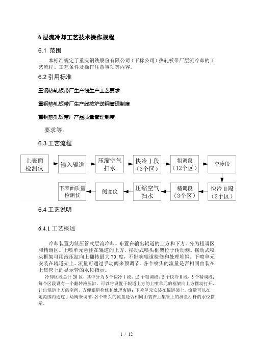
6.3工艺流程6.4工艺说明6.4.1工艺概述冷却装置为低压管式层流冷却。
布置在输出辊道的上方和下方。
分为粗调区和精调区。
上喷单元悬挂在辊道的上方,摆动式喷头框架位于传动侧。
摆动式喷头框架可用液压缸向上翻转最大70 度,不影响辊道检修和处理堆钢。
下喷单元安装在辊道架上。
流量可通过手动阀来预调节。
各个喷头的流量是否相同由装在上集管上的显示管的水位指示。
冷却区段总计20区,其中分为3个快冷Ⅰ段、12个粗调段、2个快冷Ⅱ段、3个精调段;每个区段设有一个翻转液压缸,可以将设置于辊道上方的上喷单元的框架向上方摆动打开,让出辊道上方的空间,方便辊道检修和处理废钢;下喷单元安装在辊道架上。
流量可以在一定范围内通过手动阀来调节。
各个喷头的流量是否相同由装在上集管上的测量标杆的水位指示。
6.4.2 输出辊道的控制控制方式:●输出辊道主要是速度控制,同时处理事故时可以反转。
●输出辊道的速度应与带钢运行速度同步,以免打滑划伤带钢表面。
●输出辊道要有与精轧轧制末机架和卷取机同时相匹配的升降速功能。
带钢头部从精轧末机架出来时,输出辊道速度以比精轧末机架出口速度超前15~25%运行;带钢尾部从精轧末机架出来时,输出辊道比精轧末机架出口速度滞后15~25%运行。
●当辊道上同时存在两根带钢时,每组辊道应以不同速度运行(超前或滞后)。
输出辊道可分组单动,也可与1#,2#卷取机入口前辊道联动。
●辊道外冷水控制:分8组冷却,用电磁阀控制冷却水自动启闭。
辊道检查、调整标准:●不能有破裂、掉肉的辊子;●辊面不能有尖锐的硬质粘结物;●不能有卡死的辊子、反转的辊子;●不允许相邻两根辊子成为惰辊,整个辊道惰辊不能超过3根;●辊子运行平稳、无震动和无异常噪声;●辊子冷却情况良好。
热轧层流冷却的冷却策略研究

热轧层流冷却的冷却策略研究热轧层流冷却是决定带钢组织性能的重要工艺环节,而冷却策略是决定带钢组织性能的重要工艺制度。
文章对热轧层流冷却的冷却策略进行了研究,从冷却模式、冷却速度和目标卷取温度几个方面进行了系统的分析。
标签:热轧带钢;冷却策略;工艺制度;冷却模式在热轧带钢生产中,层流冷却是重要的工艺环节,其控制的卷取温度决定了成品带钢的加工性能,力学性能和物理性能,所以热轧生产必须对层流冷却系统进行严格控制和管理。
为了达到带钢的组织性能要求,层流冷却必须制定冷却工艺制度,即冷却策略,主要包括冷却模式、冷却速度和目标卷取温度。
由于冷却策略在层流冷却中的重要作用,很多研究者对此进行了研究[1-4]。
本文从冷却模式、冷却速度和目标卷取温度几个方面进行了研究,介绍了我们提供的冷却模式,以及我们最近开发的两段式冷却模式,并对冷却速度和目标卷取温度进行了分析。
1 层流冷却系统简介层流冷却装置布置在精轧机之后,卷取机之前的输出辊道上、下方。
根据冷却集管水量的大小分为粗冷段和精冷段。
粗冷段集管的水量大,冷却能力强,带钢冷却主要集中在粗冷段;精冷段集管的水量较小,冷却能力较弱,主要是用于控制卷取温度的精度。
在第一个冷却区段的入口、最后一个冷却区段的出口、以及相邻两个冷却区段之间均设有侧喷,用于除去带钢上表面的积水。
在精轧末机架的出口装有测厚仪,测量带钢终轧时的实际厚度。
在精轧末机架的出口、粗冷段和精冷段之间,以及精冷段之后分别装有高温计,分别测量相应位置的实际温度。
层流冷却的常规设备布置图如图1所示,其中中间高温计在某些热轧厂未布置。
图1 层流冷却设备的常规布置形式2 层流冷却的冷却策略层流冷却的冷却策略是带钢冷却的工艺制度,主要包括带钢的冷却模式、冷却速度和目标卷取温度,是影响热轧最终产品组织性能的重要因素。
本文主要就冷却模式、冷却速度和目标卷取温度进行分析和研究。
2.1 冷却模式冷却模式是指层流冷却阀门的开启顺序和方向,决定了带钢从精轧机出来后,经过水冷区和空冷区的先后。
- 1、下载文档前请自行甄别文档内容的完整性,平台不提供额外的编辑、内容补充、找答案等附加服务。
- 2、"仅部分预览"的文档,不可在线预览部分如存在完整性等问题,可反馈申请退款(可完整预览的文档不适用该条件!)。
- 3、如文档侵犯您的权益,请联系客服反馈,我们会尽快为您处理(人工客服工作时间:9:00-18:30)。
首钢1580热轧层流冷却区功能说明轧制技术及连轧自动化国家重点实验室(东北大学)目录1 层流冷却区概述 (4)2 层流冷却系统设计工艺技术参数 (7)3 层流冷却区域设备组成与技术参数 (9)3.1 层流冷却集管装置 (9)3.1.1 层流冷却集管装置的功能 (9)3.1.2 层流冷却集管装置的技术参数 (9)3.1.3 层流冷却集管装置的开闭控制 (11)3.1.4 层流冷却区域带钢微跟踪控制 (14)3.1.5 层流冷却区域出口温度反馈控制 (15)3.1.6 层流冷却区域精轧机抛钢后的冷却水前馈控制 (20)3.1.7 层流冷却集管装置的操作 (22)3.1.8 层流冷却集管装置的状态显示 (24)3.2 层流冷却侧喷装置 (25)3.2.1 层流冷却侧喷装置的功能 (25)3.2.2 层流冷却侧喷装置的技术参数 (25)3.2.3 层流冷却侧喷装置的开闭控制 (25)3.2.4 层流冷却侧喷装置的操作 (26)3.2.5 层流冷却侧喷装置的状态显示 (26)3.3 层流冷却压缩空气吹扫装置 (26)3.3.1 层流冷却压缩空气吹扫装置的功能 (26)3.3.2 层流冷却压缩空气吹扫装置的技术参数 (26)3.3.3 层流冷却压缩空气吹扫装置的开闭控制 (27)3.3.4 层流冷却压缩空气吹扫装置的操作 (27)3.3.5 层流冷却压缩空气吹扫装置的状态显示 (27)3.4 层流冷却上集管倾翻装置 (27)3.4.1 层流冷却上集管倾翻装置的功能 (27)3.4.2 层流冷却上集管倾翻装置的技术参数 (27)3.4.3 层流冷却上集管倾翻装置的控制 (27)3.4.4 层流冷却上集管倾翻装置的操作 (28)3.5 层流冷却边部遮蔽装置 (28)3.5.1 层流冷却边部遮蔽装置的功能 (28)3.5.2 层流冷却边部遮蔽装置的技术参数 (29)3.5.3 层流冷却边部遮蔽装置的控制 (29)3.5.4 层流冷却边部遮蔽装置的操作 (29)3.5.5 层流冷却边部遮蔽装置的状态显示 (29)3.6 热输入辊道冷却装置 (29)3.6.1 热输入辊道冷却装置的功能 (29)3.6.2 热输入辊道冷却装置的技术参数 (29)3.6.3 热输入辊道冷却装置的开闭控制 (30)3.6.4 热输入辊道冷却装置的操作 (30)3.7 层流冷却区域仿真功能 (30)3.8 层流冷却过程计算机控制 (30)3.8.1 层流冷却过程计算机控制功能 (30)3.8.2 层流冷却过程计算机控制设定参数 (31)3.8.3 层流冷却过程计算机控制投入方法 (31)3.8.4 层流冷却过程计算机控制的操作 (31)3.8.5 层流冷却过程计算机控制的状态显示 (31)1层流冷却区概述层流冷却设备安装在精轧机F7机架出口至1号地下卷取机之间,主要由层流冷却集管装置(包括层流冷却精冷上集管装置、层流冷却精冷下集管装置、层流冷却微冷上集管装置及层流冷却微冷下集管装置)、层流冷却侧喷装置、层流冷却压缩空气吹扫装置、层流冷却上集管倾翻装置、层流冷却边部遮蔽装置及热输入辊道冷却装置组成。
层流冷却基础自动化系统采用高性能可编程控制器,主要功能为执行过程计算机的设定结果,采用前馈及反馈等控制手段,协同过程控制系统,将卷取温度控制在设定的范围内,使带钢力学性能和金相组织达到预定的质量要求。
层流冷却基础自动化系统采用1面主PLC控制柜(控制柜编号为:CERPLC601)和4面远程I/O控制柜(控制柜编号为:CMFIO10~CMFIO13)。
主PLC控制柜尺寸(宽×深×高)为1000×800×2200mm;所有远程I/O控制柜尺寸(宽×深×高)为1400×500×1800mm。
主PLC控制柜布置在卷取电气室;远程I/O控制柜布置在层流冷却设备附近地下室。
主PLC采用GE Fanuc PAC Systems RX7i大型可编程控制器系统。
PAC Systems是GE Fanuc公司推出的高性能控制器,是GE90-70系列PLC的升级产品,速度是GE 90-70系列PLC的7~10倍。
RX7i系列采用VME总线机架方式安装,CPU采用Intel PIII处理器,10M 内存,集成2个10/100M自适应以太网卡。
主机架采用新型17槽VME机架。
4个远程I/O站分别为层流冷却控制1#远程I/O站、层流冷却控制2#远程I/O 站、层流冷却控制3#远程I/O站和层流冷却控制4#远程I/O站。
远程I/O站选用VersaMax产品,通过PROFIBUS DP总线与主PLC交换数据。
层流冷却基础自动化系统与层流冷却过程控制系统、层流冷却HMI系统精轧区基础自动化系统及卷取区基础自动化系统之间采用内存映像网进行数据交换。
边部遮蔽装置采用机电一体化产品,通过PROFIBUS DP总线与层流冷却基础自动化系统交换数据。
在整个冷却区设置11台红外测温仪,具体布置为:在层流冷却装置入口处设1台红外测温仪,用于检测带钢终轧温度;在层流冷却第11组和第12组冷却装置之间设置2台红外测温仪,用于检测带钢中间冷却温度;在层流冷却装置出口处设4台红外测温仪,用于检测带钢冷后温度;在卷取机入口处设4台红外测温仪,由于检测带钢卷取温度。
红外测温仪反馈信号为4~20mA的电流模拟信号。
层流冷却区域内红外测温仪选型及安装位置如表1.1所示。
在整个冷却区设置6台电磁流量计,具体布置在精调第2组第1根上、下集管、精调第5组第1根上、下集管及微调第21组第8根上、下集管。
电磁流量计反馈信号为4~20mA的电流模拟信号,用于流量监视和控冷过程控制。
层流冷却区域内电磁流量计选型及安装位置如表1.2所示。
在高位水箱上安装液位液温测量仪,对高位水箱内的冷却水液位和水温进行实时测量。
液温测量仪用于冷却模型参数的温度补偿。
仪表给出4~20mA的模拟信号。
高位水箱液位及液温测量仪的参数如表1.3所示。
2层流冷却系统设计工艺技术参数冷却带钢厚度: 1.2~12.7mm 冷却带钢宽度:700~1450mm 终轧温度:870~900℃卷取温度:200~850℃冷却水温度:35℃冷却段长度:97920mm冷却单元组数:21组冷却段数:上部:微调段:16根集管精调段:94根集管下部:微调段:16根集管精调段:76根集管每根上集管鹅颈管总数:精调:86根微调:43根鹅颈管水压:0.574N/cm2每根集管的总水量:精调:71.2m3/h微调:35.6m3/h 上部总水量:7577m3/h每根下集管喷嘴数:精调:35个微调:26个每根下集管的喷水量:精调:28.6m3/h微调:21.2m3/h 下喷水压:0.0415bar下部总水量:7850m3/h上喷和下喷总水量(不含输出辊道冷却):约14500m3/h 侧喷嘴数量:46个侧喷压力:12bar每个喷嘴的侧喷水量:8 m3/h侧喷总水量:384m3/h气动压力:4-6bar倾翻液压缸数:21个(位于轧线传动侧)3层流冷却区域设备组成与技术参数层流冷却区域设备主要可以分为层流冷却集管装置(包括层流冷却精冷上集管装置、层流冷却精冷下集管装置、层流冷却微冷上集管装置及层流冷却微冷下集管装置)、层流冷却侧喷装置、层流冷却压缩空气吹扫装置、层流冷却上集管倾翻装置、层流冷却边部遮蔽装置及热输入辊道冷却装置六部分。
3.1层流冷却集管装置在精轧机F7机架出口与1号地下卷取机间的热输出辊道上下方,布置21组层流冷却集管,前19组为精冷段,后2组为微冷段。
精冷段作为主冷区,微冷段为微调区和反馈控制区。
出水方式为上集管上排布U型管,形成管层流。
3.1.1层流冷却集管装置的功能层流冷却集管装置功能是:带钢经过精轧机组轧制后,进入层流冷却区域;层流冷却基础自动化系统及过程控制系统通过实时控制层流冷却上下集管装置水量配比及水量分布,将热轧带钢冷却到工艺要求的卷取温度,使其力学性能和金相组织结构达到预定的质量要求。
3.1.2层流冷却集管装置的技术参数3.1.2.1精冷段1~4组上部层流集管装置技术参数每组冷却装置由6根Φ219×6mm层流集管组成。
每根层流集管上面安装2排管径为Φ22×2mm的U型管,2排总计43×2=86个U型管。
每根精冷上集管供水量为71.2 m3/h,每组上集管供水量为71.2×6=427.2 m3/h,精冷段1~4组上集管的总供水量为427.2×4=1708.8 m3/h。
冷却水对带钢表面的冲击压力0.06MPa。
每根上集管为1个控制单元,用一个阀组来控制,每个阀组包括一个DN200的手动蝶阀和二个DN200的气动开闭阀。
由24V直流电源来控制气动开闭阀的开关。
总计共6×4=24个DO控制点。
3.1.2.2精冷段5~14组上部层流集管装置技术参数每组冷却装置由4根Φ219×6mm层流集管组成。
每根层流集管上面安装2排管径为Φ22×2mm的U型管,2排总计43×2=86个U型管。
每根精冷上集管供水量为71.2 m3/h,每组上集管供水量为71.2×4=284.8 m3/h,精冷段5~14组上集管的总供水量为284.8×10=2848 m3/h。
冷却水对带钢表面的冲击压力0.06MPa。
每根上集管为1个控制单元,用一个阀组来控制,每个阀组包括一个DN200的手动蝶阀和二个DN200的气动开闭阀。
由24V直流电源来控制气动开闭阀的开关。
总计共4×10=40个DO控制点。
3.1.2.3精冷段15~19组上部层流集管装置技术参数每组冷却装置由6根Φ219×6mm层流集管组成。
每根层流集管上面安装2排管径为Φ22×2mm的U型管,2排总计43×2=86个U型管。
每根精冷上集管供水量为71.2 m3/h,每组上集管供水量为71.2×6=427.2 m3/h,精冷段15~19组上集管的总供水量为427.2×5=2137.5 m3/h。
冷却水对带钢表面的冲击压力0.06MPa。
每根上集管为1个控制单元,用一个阀组来控制,每个阀组包括一个DN200的手动蝶阀和二个DN200的气动开闭阀。
由24V直流电源来控制气动开闭阀的开关。
总计共6×5=30个DO控制点。
3.1.2.4精冷段1~19组下部喷射集管装置技术参数每组冷却装置由12根Φ140×8mm喷射集管组成。
每根喷射集管上面安装1排管径为Φ17×3.2mm的喷嘴,总计35个喷嘴。
每根精冷下集管供水量为28.6 m3/h,每组下集管供水量为28.6×12=343.2 m3/h,精冷段1~19组下集管的总供水量为343.2×19=6520.8 m3/h。