厨卫安装说明书(中英文对照)
厨房橱柜安装指南说明书

Kitchen CabinetInstallation GuideThe instructions given here serve as a general guideline on how to install frameless cabinets in a reasonably simple installation. Many cabinet designs and installations may be far more complex and beyond the scope of these instructions and require a professional installer.∙Tools Required∙Layout and Planning the Installation∙Cabinet Installation Order∙Installing Cabinets Level∙Fastening Cabinets to the Wall∙Fastening Cabinets Together∙Installing Fillers∙Installing Trim∙Adjusting Hinges and DrawersWarning: Kitchen installations typically involve gas, high voltage wiring, plumbing and mechanical details like heating and AC vents. This guide only covers cabinet installation. At a minimum, if you’re not well versed in these areas make sure that all power is shut off to exposed wiring and gas valves are closed to gas supply lines.∙Tools Required• Tape Measure • Pencil • 3 to 4 foot Level • 3/16" Drill Bit • Phillips Head Screwdriver •#2 Square Drive Bit*• Electric Drill • Hammer • Wood Shims • Phillips Head Screw Gun • Handsaw • Chalk Line • Step Ladder • Extension Cord • Pry Bar • Clamps • Carpenter’s Square • NOTE: If “C” clamps are used, protect material between finished case of the cabinet and the clamp.∙Additional tools that make the job easier:Small Table saw •Power Miter Saw • Laser Level • Stud FinderLocating the Highpoint on the Floor for a WallLayout andPlanning the Installation1. Take inventory of the cabinets as per the plan or order.2. Find the high spot in the floor using a level as shown below.3. Measure up the wall 34 ½” above the high spot and draw a level line anywhere that base cabinets will be installed. (This means that this line will measure greater than 34 ½” above the floor in most places along the wall.)4. Find and mark the studs. This can be done by trial and error of driving a nail in the wall until you find a stud or use an electronic stud finder. Studs will usually be every 16” center to center.Locating the Highpoint on the Floor for an Adjacent WallLocating the Highpoint on the Floor Between Two WallsStep 2Place a mark 34 ½” up from the high spot in floor5. It is best when installing a larger kitchen to mark the cabinet positions and code (size) on the wall. Better to find out now if things aren’t going to fit just right than after you’ve installed several cabinets.6. Unbox the cabinets and be cautious not to drag them across the floor. Save some cardboard to rest thecabinets on to prevent damage to the cabinets and the floor.7. Remove all doors, drawers and shelves, being careful to mark them so that they go back on correct cabinets. Removing the doors can be done without tools as the hinges are “clip ‐on”.Removing drawer boxes are different depending on the type drawer.Standard drawers can be removed by simply pulling the drawer out until it stops, then lift up the front of the drawer and remove the drawer.Dovetail drawers can be removed by pulling the drawer out until it stops. Then reach under the drawer box onboth sides just behind the drawer front. Pull the clipsholding both of them simultaneously while lifting up on the drawer box. Then slide the drawer out.∙Cabinet Installation Order1.Determining the installation order of the cabinets depends on the plan. As a general rule it is better tostart with wall cabinets in the corner and work out. However, if you have “tall” cabinets, like a pantry or oven cabinet in the plan, it is critical to make sure that the tall cabinet is used to determine the top alignment of wall cabinets.∙Installing Cabinets Level1.Nearly every floor, in any house, will not be level and flat. The illustrations below show an exaggeratedview of why leveling cabinets to the high point in the floor is critical.Wrong Right2.Cabinets should be shimmed up from the floor level to the 34 ½” line with wood or composite shims.3.Cabinets should also be shimmed out from the wall to maintain a straight line. Hampton Bay DesignerSeries cabinets are designed to be a “frameless construction” which means when the cabinets arescrewed together they will be forced into a straight line regardless of how wavy or bowed the wall orsurface they’re fastened to may be.WrongRightFastening Cabinets to the Wall1. Screw wall cabinets and tall cabinets to the predetermined height through the back panel into a stud. Make sure to place screws 1” below the top and 1” above the bottom. Measure and mark the studlocation on the cabinet before drilling. Use #8 x 2‐1/2” flat head screws when fastening through a single layer of drywall into wood studs.2. Place a screw at the top of the cabinet and the bottom of a cabinet in as many studs as can be located in the cabinet width.3. Level the cabinets.4. Important: Make sure the cabinets are square by placing a framing square inside or outside of the cabinet. Frameless cabinets can be racked (or slightly twisted) before they are fastened in place.W3036W3036W3036Correcting for a “Bowed In”or “Bellied”Wall ConditionBoxes are at an angle to each otherBox faces are not alignedW3036W3036W3036Proper shimming will allow cabinet boxes to be aligned along a flat plane and the door facia to be adjusted within acceptable tolerancesPlace screws 1” below the inside top ofPlace screws 1” above the inside bottom of cabinet∙Fastening Cabinets Together1. Align cabinet frames together carefully.2. Cabinet cases can be clamped together using various kinds of clamps, however use caution with any kind of steel clamp to not damage the surface material of the cabinet.3. Screw cabinets together with #7 x 1‐1/8” flat head screws.∙ Installing fillers1. Cabinets come is 3” increments in width, therefore fillers will be required when cabinets are to fit between walls.2. Measure the space between the wall and the cabinet at the top, middle and bottom. If the dimensionsare close to the same you can rip (saw) the filler in a straight line to the proper width to fit.3. Next, predrill holes for 1¼” screws and screw the fillers from the inside of the cabinet.4. In a case where the wall is not plumb, the filler will have to be cut to fit to the uneven wall.3”2¾”Installing Trim1. Installing crown molding can be accomplished in a variety of ways depending on the application. Using “frameless cabinets” means that a sub ‐crown molding will always have to be screwed to the top of the cabinet case to attach the crown molding to.ATSM as Sub Crown-Crown Spans to CeilingATSM by Itself as TopscribeATSM as Sub CrownABU PB58as Sub Crown AMLR 2as Sub CrownSide ViewFront ViewSide ViewFront ViewHinge Removal and ReinstallationTo Remove a Mounted Hinge:Push the Release Plunger in from the Back of the Hinge The Hinge Will Disengage from the Mounting PlateHingeMounting PlateRelease PlungerTo Remount a Hinge:Align and Insert theHinge Hooks into the Front of the Mounting PlatePush the Back of the Hinge into the Plate Until it ClicksHinge HooksAdjusting Doors and DrawersHinge AdjustmentUp and Down AdjustmentSide to Side Adjustment and Out Open DoorViewOut of AlignmentCondition Alignment ConditionCorrected10Drawer AdjustmentStandard DrawerDovetail Drawer Adjustment ‐ To Adjust the dovetail drawer for alignment, slide the white plastic clip on the under side of the drawer back and forth to raise and lower the left and right side of the drawer.Rear View ofOpen Drawer Out of Alignment Condition Alignment ConditionCorrectedScrewScrews Raises RaisesLowersThis warranty covers substantial defects in materials and workmanship in your Hampton Bay Designers Series products under normal home use. This warranty is offered only to the original consumer purchaser and may not be transferred. The coverage of this warranty lasts for the lifetime of the original purchaser, so long as he or she owns the home in which the product was first installed.What This Warranty Covers: RSI Home Products, Inc. (“RSI”) warrants its parts and products to be free of substantial defects in materials and workmanship from the original date of purchase under normal home use. This warranty is offered to the original consumer purchaser only and may not be transferred.How Long The Warranty Lasts: Coverage for all Kitchen Cabinets and Accessories lasts for the life of the product. What RSI Home Products Will Do Under The Warranty: During the warranty period, RSI, at its option, will repair or replace any part or product that proves to have substantial defects in materials or workmanship, or RSI will provide an equivalent replacement product. In keeping with our policy of continuous product improvement, RSI reserves the right to change specifications in design and materials without notice and with no obligation to retrofit products we previously manufactured.How State Law Applies: This warranty gives you specific legal rights, and you may also have other rights that vary from state to state.Implied Warranties: RSI disclaims any implied warranty of merchantability, and there are no warranties that extend beyond the descriptions on the face hereof. T o the extent that such disclaimer is not valid under applicable law, any implied warranty shall be coextensive in duration with this warranty.Wood, Aging And Printing Limitations: Because of the varying natural characteristics of wood and the effects of aging, product shown in displays and/or printed materials will not be an exact match to new cabinetry you will receive. Depending on the wood characteristics, the age of a sample and the environment of the showroom, samples will show some degree of variation from new product. In addition, you should not expect all doors, drawer fronts, trim or molding to match exactly in either finish or grain. Variation in wood is normal and unavoidable. In addition, it is not possible to match our colors exactly in printed materials. Therefore, you should view the actual samples when making your color selection.What This Warran ty Does Not Cover: T his warranty does not cover any problems or damage which result from improper transportation, improper installation, mishandling, misuse, abuse, neglect, abnormal use, commercial use, improper maintenance, non-RSI repairs, accidents, or acts of God, such as hurricanes, fire, earthquakes or floods. This warranty, and any applicable implied warranties, does not cover incidental or consequential damages arising from any defects in the product, such as labor charges for installation or removal of the product or any associated products. This warranty does not cover defects or damage caused by normal wear and tear, alterations, environmental conditions, humidity absorption, or mold. In addition, variations in hand carved items, wood grain, finish color, aging or other natural wood and stain characteristics are not considered defects and are not covered by this warranty. Some states do not allow the exclusion or limitation of incidental or consequential damages, so the above limitation or exclusion may not apply to you. U180215 09/15Limited Lifetime WarrantyVendor InformationEmail: ***************************Address: 11350 Riverside Dr. Mira Loma, CA 91752Customer Service #: 800-230-5661Fax # for Order Processing: 844-554-0636。
厨卫电器 Hob Hob PKE345CA1 说明书

HobPKE345CA1.[en]Instruction manual Hoben2Table of contents8Intended use. . . . . . . . . . . . . . . . . . . . . . . . . . . . . 3(Important safety information . . . . . . . . . . . . . . . 3]Causes of damage. . . . . . . . . . . . . . . . . . . . . . . . 4Overview . . . . . . . . . . . . . . . . . . . . . . . . . . . . . . . . . . .47Environmental protection . . . . . . . . . . . . . . . . . . 4Energy-saving tips . . . . . . . . . . . . . . . . . . . . . . . . . . . .4Environmentally-friendly disposal . . . . . . . . . . . . . . . . .4*Getting to know your appliance . . . . . . . . . . . . . 5The control panel. . . . . . . . . . . . . . . . . . . . . . . . . . . . .5Hotplate and residual heat indicator. . . . . . . . . . . . . . .51Operating the appliance . . . . . . . . . . . . . . . . . . . 6Switching the hob on and off . . . . . . . . . . . . . . . . . . . .6Setting a hotplate. . . . . . . . . . . . . . . . . . . . . . . . . . . . .6Table of cooking times. . . . . . . . . . . . . . . . . . . . . . . . .6D Cleaning . . . . . . . . . . . . . . . . . . . . . . . . . . . . . . . . 7Ceramic . . . . . . . . . . . . . . . . . . . . . . . . . . . . . . . . . . . .7Hob surround. . . . . . . . . . . . . . . . . . . . . . . . . . . . . . . .74Customer service. . . . . . . . . . . . . . . . . . . . . . . . . 7E number and FD number . . . . . . . . . . . . . . . . . . . . . .7Additional information on products, accessories, replacement parts and services can be found at and in the online shop 3.( &$Intended use en38Intended useR ead these instructions carefully. Please keep the instruction and installation manual, as well as the appliance certificate, in a safe place for later use or for subsequent owners.Check the appliance for damage afterunpacking it. Do not connect the appliance if it has been damaged in transport.Only a licensed professional may connect appliances without plugs. Damage caused by incorrect connection is not covered under warranty.This appliance is intended for private domestic use and the household environment only. The appliance must only be used for the preparation of food and beverages. Thecooking process must be supervised. A short cooking process must be supervised without interruption. Only use the appliance in enclosed spaces.This appliance is intended for use up to a maximum height of 2000 metres above sea level.This appliance is not intended for operation with an external clock timer or a remote control.This appliance may be used by children over the age of 8 years old and by persons with reduced physical, sensory or mental capabilities or by persons with a lack of experience or knowledge if they aresupervised or are instructed by a person responsible for their safety how to use the appliance safely and have understood the associated hazards.Children must not play with, on, or around the appliance. Children must not clean theappliance or carry out general maintenance unless they are at least 15 years old and are being supervised.Keep children below the age of 8 years old at a safe distance from the appliance and power cable.(Important safety information:Warning – Risk of fire!■Hot oil and fat can ignite very quickly. Never leave hot fat or oil unattended. Never use water to put out burning oil or fat. Switch off the hotplate. Extinguish flames carefully using a lid, fire blanket or something similar. ■The hotplates become very hot. Neverplace combustible items on the hob. Never place objects on the hob.■The appliance gets hot. Do not keep combustible objects or aerosol cans in drawers directly underneath the hob.■Do not use hob covers here.They can cause accidents, for example due to overheating, catching fire or materials shattering.:Warning – Risk of burns!■The hotplates and surrounding area (particularly the hob surround, if fitted) become very hot. Never touch the hot surfaces. Keep children at a safe distance.■The hotplate heats up but the display does not work. Switch off the circuit breaker in the fuse box. Contact the after-sales service.■It is only allowed to use safety devices, e.g. hob guards, which have been approved by ourselves. Unsuitable safety devices or hob guards may result in accidents.:Warning – Risk of electric shock!■Incorrect repairs are dangerous. Repairs may only be carried out and damaged power cables replaced by one of our trained after-sales technicians. If theappliance is defective, unplug the appliance from the mains or switch off the circuit breaker in the fuse box. Contact the after-sales service.■Do not use any high-pressure cleaners or steam cleaners, which can result in an electric shock.■ A defective appliance may cause electric shock. Never switch on a defectiveappliance. Unplug the appliance from the mains or switch off the circuit breaker in the fuse box. Contact the after-sales service.■Cracks or fractures in the glass ceramic may cause electric shocks. Switch off the circuit breaker in the fuse box. Contact the after-sales service.en Causes of damage4:Warning – Risk of injury!Saucepans may suddenly jump due to liquid between the pan base and the hotplate.Always keep the hotplate and saucepan bases dry.]Causes of damageC aution!■Rough pot and pan bases scratch the ceramic.■Avoid boiling pots dry. This may cause damage.■Never place hot pots or pans on the control panel, the display area or the surround. This may cause damage.■Damage can occur if hard or pointed objects fall on the hob. ■Aluminium foil and plastic containers melt on hot hotplates. Oven protective foil is not suitable for your hob.OverviewYou will find the most frequently caused damage in the following table.7Environmental protectionI n this section, you can find information about saving energy and disposing of the appliance.Energy-saving tips■Always place suitable lids on saucepans. When cooking without a lid, considerably more energy is required. A glass lid means that you can see inside without having to lift the lid.■Use pots and pans with even bases. Uneven bases increase energy consumption.■The diameter of pot and pan bases should be the same size as the hotplate. In particular, small saucepans on the hotplate cause energy losses. Please note: cookware manufacturers often indicate the upper diameter of the saucepan. This is usually bigger than the diameter of the base of the pan.■Use a small saucepan for small quantities. A larger, less full saucepan requires a lot of energy.■Cook with only a little water. This will save energy. Vitamins and minerals in vegetables are preserved.■Always cover as large an area of the hotplate as possible with your saucepan.■Switch to a lower heat setting in good time.■Select a suitable ongoing cooking setting. You will waste energy by using an ongoing cooking setting which is too high.■Use the residual heat of the hob. For longer cooking times, you can switch the hotplate off 5-10 minutes before the end of the cooking time.Environmentally-friendly disposalDispose of packaging in an environmentally-friendly manner.This appliance is labelled in accordance with European Directive 2012/19/EU concerning used electrical and electronic appliances (waste electrical and electronic equipment - WEEE). The guideline determines theframework for the return and recycling of used appliances as applicable throughout the EU.Getting to know your appliance en5*Getting to know your applianceY ou can find the hob dimensions in the overview of models. ~ Page 2The control panelHotplate and residual heat indicatorThe hotplate and residual heat indicator lights up when a hotplate is warm:■Hotplate indicator - during operation, shortly after you have switched on a hotplate.■Residual heat indicator - after cooking, when the hotplate is still warm.You can use the residual heat to save energy, e.g. tokeep a small meal warm or to melt chocolate.en Operating the appliance61Operating the applianceI n this section, you can find out how to set thehotplates. The table shows heat settings and cooking times for various meals.Switching the hob on and offYou can switch the hob on and off with the hotplate controls.Setting a hotplateAdjust the heat setting of the hotplates using the hotplate controls.Heat setting 1 = lowest setting Heat setting 9 = highest settingNote: Hotplate temperature is regulated by the heat switching on and off.The heat may also switch on and off at the highest setting.This ensures e.g.:■sensitive components are protected from overheating ■the appliance is protected from electrical overload ■better cooking results are achievedTable of cooking timesYou can find a few examples in the following table. Cooking times and heat settings may vary depending on the type of food, its weight and quality. Deviations are therefore possible.For bringing liquids to the boil, use heat setting 9.Stir thick liquids occasionally.Food that needs to be seared quickly or food which loses a lot of liquid during initial frying is best seared in several small portions.Tips for energy-saving cooking can be found in the "Environmental protection" section.~ Page 4Cleaning en7D CleaningS uitable maintenance and cleaning products can be purchased from the after-sales service or in our e-Shop.CeramicClean the hob after each use. This will prevent spills from burning onto the ceramic.Only clean the hob when it has cooled down e only cleaning agents which are suitable for glass ceramic. Follow the cleaning instructions on the packaging.Never use:■Undiluted washing-up liquid■Detergent intended for dishwashers ■Scouring agents■Harsh cleaning agents such as oven spray or stain remover■Abrasive sponges■High-pressure cleaners or steam jet cleanersGround-in dirt can be best removed with a glass scraper, available from retailers. Please note the manufacturer's instructions.You can also obtain a suitable glass scraper from our after-sales service or from the e-Shop.Using special sponges to clean glass ceramic achieves great cleaning results.Hob surroundTo prevent damage to the hob surround, observe the following instructions:■Use only hot soapy water.■Wash new sponge cloths thoroughly before use.■Do not use any sharp or abrasive agents.■Do not use the glass scraper.4Customer serviceO ur after-sales service is there for you if your appliance needs to be repaired. We will always find anappropriate solution, also in order to avoid after-sales personnel having to make unnecessary visits.E number and FD numberPlease quote the E-number (product number) and the FD number (production number) of your appliancewhen contacting the after-sales service. The rating plate bearing these numbers can be found on the appliance certificate.Please note that a visit from an after-sales serviceengineer is not free of charge in the event of misuse of the appliance, even during the warranty period.Please find the contact data of all countries in the enclosed customer service list.To book an engineer visit and product advice Rely on the professionalism of the manufacturer. You can therefore be sure that the repair is carried out by trained service technicians who carry original spare parts for your appliances.GB ***********Calls charged at local or mobile rate.IE 01450 26550.03 € per minute at peak. Off peak 0.0088 € per minute.*9001197937* 9001197937971201(B)。
厨房墙壁水龙头安装说明书:Elkay Ella Wall Pot Filler Faucet
ELKAY LIMITED LIFETIME FAUCET WARRANTY ON RESIDENTIAL FAUCETS
Limited Lifetime Functional and Finish Warranty Elkay warrants to the original consumer purchaser that the Elkay faucet purchased will be free from defects in material and workmanship for as long as the original consumer purchaser owns the faucet. Elkay will, at its option, supply replacement parts (or if no longer available a comparable product) if the faucet fails due to a defect in material or workmanship. This warranty does not apply in the event of product surface damage caused by abuse, misuse or improper care and maintenance. This warranty excludes damage caused by harsh or abrasive cleaners and/or materials. This warranty excludes all industrial, commercial and business use, whose purchasers are hereby extended a limited lifetime on mechanical parts and 5 years on finish. Product replacement does not include transportation cost or labor installation cost. Elkay reserves the right to examine product in question and its installation prior to replacement.
厨房设备安装说明书
厨房设备安装说明书一、安装前准备1.1 确认设备完整性在开始安装之前,请检查所购买的厨房设备是否完整,包括主机、配件、工具等。
如发现任何缺失或损坏,请及时联系供应商解决。
1.2 确定安装位置根据设备的尺寸和功能要求,选择合适的安装位置。
确保设备的周围有足够的空间,以便于设备的正常运行和维护。
1.3 检查供电和水源在安装之前,确保供电和水源的可用性。
检查电源插座是否符合设备的电压要求,并确保水源管道的连接正常。
二、安装步骤2.1 安装主机根据设备的安装图纸或说明书,将主机固定在预定的位置。
使用螺丝刀或扳手等工具,确保主机稳固地安装在支架或墙壁上。
2.2 连接电源和水源根据设备的电气接线图和水源连接图,正确接线并连接电源和水源。
确保接线牢固可靠,避免电源和水源泄露或短路。
2.3 安装配件根据设备的配件清单,安装相应的配件。
例如,安装抽油烟机的排气管道、安装烤箱的烤盘等。
注意遵循配件的安装说明,确保正确安装并固定。
2.4 调试设备在安装完成后,进行设备的调试。
根据设备的操作手册,启动设备并进行功能测试。
确保设备的各项功能正常运行,并调整相应的参数。
三、使用和维护3.1 使用说明在开始使用设备之前,仔细阅读设备的使用说明书。
了解设备的操作方法、注意事项和安全规定。
确保操作人员掌握正确的使用方法,避免不必要的事故和损坏。
3.2 日常维护定期进行设备的日常维护,包括清洁、检查和保养。
根据设备的维护手册,清洁设备的内部和外部部件,检查设备的电气和水源连接是否正常,保养设备的关键部件。
3.3 故障排除在设备使用过程中,如果出现故障或异常情况,请及时采取相应措施。
首先检查设备的电源和水源是否正常,然后根据设备的故障排除手册,逐步排除故障。
3.4 定期检查定期请专业技术人员对设备进行检查和维护。
根据设备的保养周期,进行相应的保养和维修工作。
及时更换老化和损坏的部件,确保设备的正常运行。
四、安全注意事项4.1 电气安全在安装和使用设备时,务必遵守电气安全规定。
家庭煤气烹饪器安装与用户说明书
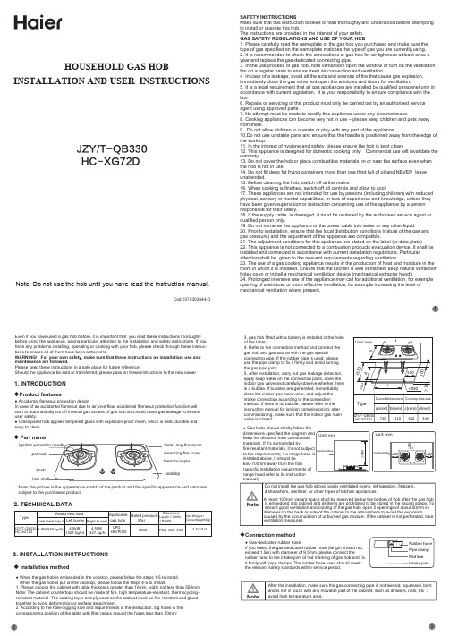
HOUSEHOLD GAS HOBINSTALLATION AND USER INSTRUCTIONSNote: Do not use the hob until you have read the instruction manual.1. INTRODUCTION2. TECHNICAL DATA3. INSTALLATION INSTRUCTIONS◆Product features◆ Part name◆ Installation method◆Connection methodJZY/T-QB330HC-XG72DEven if you have used a gas hob before, it is important that you read these instructions thoroughly before using the appliance, paying particular attention to the installation and safety instructions. If you have any problems installing, operating or cooking with your hob, please check through these instruc-tions to ensure all of them have been adhered to.WARNING! For your own safety, make sure that these instructions on installation, use and maintenance are followed.Please keep these instructions in a safe place for future reference.Should the appliance be sold or transferred, please pass on these instructions to the new owner .Note: the picture is the appearance sketch of the product and the specific appearance and color are subject to the purchased product.cooktopknob pot rackthermocoupleOuter-ring fire cover inner-ring fire cover≥1000≥200≥200≥200Unit: mm Rubber hose Pipe clamp Red line Intake jointcombustibles combustiblesUnit: mmDo not install the gas hob above poorly ventilated ovens, refrigerators, freezers, dishwashers, sterilizer, or other types of kitchen appliances.After the installation, make sure the gas connecting pipe is not twisted, squeezed, bent and is not in touch with any movable part of the cabinet, such as drawers, rails, etc .; avoid high temperature area.At least 100mm vacant space shall be reserved below the bottom of hob after the gas hob is embedded into cabinet and all items are prohibited to be stored in the vacant space. To ensure good ventilation and cooling of the gas hob, open 2 openings of about 50mm in diameter on the back or side of the cabinet to the atmosphere to avoid the explosioncaused by the accumulation of unburned gas mixture. If the cabinet is not perforated, take ventilation measures.NoteNote● Accidental flameout protection designIn case of an accidental flameout due to air, overflow, accidental flameout protection function will start to automatically cut off internal gas access of gas hob and avoid mass gas leakage to ensure user safety.● Glass panel hob applies tempered glass with explosion-proof mesh, which is safe, durable and easy to clean.● When the gas hob is embedded in the cooktop, please follow the steps 1-5 to install. When the gas hob is put on the cooktop, please follow the steps 4-5 to install.1. Please choose the cabinet with table thickness greater than 16mm, width not less than 550mm;Note: The cabinet countertops should be made of fire, high temperature-resistant, thermocycling- resistant material. The coating layer and plywood on the cabinet must be fire-resistant and glued together to avoid deformation or surface detachment.2. According to the hole-digging size and requirements in the instruction, dig holes in the corresponding position of the table with fillet radius around the holes less than 50mm;3. gas hob fitted with a battery is installed in the hole of the table;4. Refer to the connection method and connect the gas hob and gas source with the gas specialconnecting pipe. If the rubber pipe is used, please use the pipe clamp to fix it firmly and avoid turning the gas pipe joint;5. After installation, carry out gas leakage detection, apply soap water on the connection parts, open the indoor gas valve and carefully observe whether there is a bubble. If bubbles are generated, immediately close the indoor gas main valve, and adjust the intake connection according to the connection method. If there is no bubble, please refer to the instruction manual for ignition commissioning; after commissioning, make sure that the indoor gas main valve is closed.● Gas hobs should strictly follow thedimensions specified the diagram and keep the distance from combustible materials. If it’s surrounded byfire-resistant materials, it’s not subject to the requirements; if a range hood is installed above, it should be 650-700mm away from the hob(specific installation requirements of range hood refer to its instruction manual).● Gas-dedicated rubber hoseIf you select the gas-dedicated rubber hose (length should not exceed 1.5m) with diameter of 9.5mm, please connect therubber hose to the intake joint of red marking of gas hob and fix it firmly with pipe clamps. The rubber hose used should meet the relevant safety standards within service period.Cod:0070303644-DSAFETY INSTRUCTIONSMake sure that this instruction booklet is read thoroughly and understood before attempting to install or operate this hob.The instructions are provided in the interest of your safety. GAS SAFETY REGULATIONS AND USE OF YOUR HOB1. Please carefully read the nameplate of the gas hob you purchased and make sure the type of gas specified on the nameplate matches the type of gas you are currently using.2. It is recommended to check the connections of gas hob for air tightness at least once a year and replace the gas-dedicated connecting pipe.3. In the use process of gas hob, note ventilation, open the window or turn on the ventilation fan on a regular basis to ensure fresh air convection and ventilation.4. In case of a leakage, avoid all the acts and sources of fire that cause gas explosion, immediately close the gas valve and open the windows and doors for ventilation.5. It is a legal requirement that all gas appliances are installed by qualified personnel only in accordance with current legislation. It is your responsibility to ensure compliance with the law.6. Repairs or servicing of this product must only be carried out by an authorised service agent using approved parts.7. No attempt must be made to modify this appliance under any circumstances.8. Cooking appliances can become very hot in use – please keep children and pets away from them.9. Do not allow children to operate or play with any part of the appliance.10.Do not use unstable pans and ensure that the handle is positioned away from the edge of the worktop.11. In the interest of hygiene and safety, please ensure the hob is kept clean.12. This appliance is designed for domestic cooking only. Commercial use will invalidate the warranty.13. Do not cover the hob or place combustible materials on or near the surface even when the hob is not in use.14. Do not fill deep fat frying containers more than one third full of oil and NEVER leave unattended.15. Before cleaning the hob, switch off at the mains.16. When cooking is finished, switch off all controls and allow to cool.17. These appliances are not intended for use by persons (including children) with reduced physical, sensory or mental capabilities, or lack of experience and knowledge, unless they have been given supervision or instruction concerning use of the appliance by a person responsible for their safety.18. If the supply cable is damaged, it must be replaced by the authorised service agent or qualified person only.19. Do not immerse the appliance or the power cable into water or any other liquid.20. Prior to installation, ensure that the local distribution conditions (nature of the gas and gas pressure) and the adjustment of the appliance are compatible.21. The adjustment conditions for this appliance are stated on the label (or data plate)22. This appliance is not connected to a combustion products evacuation device. It shall be installed and connected in accordance with current installation regulations. Particular attention shall be given to the relevant requirements regarding ventilation.23. The use of a gas cooking appliance results in the production of heat and moisture in the room in which it is installed. Ensure that the kitchen is well ventilated: keep natural ventilation holes open or install a mechanical ventilation device (mechanical extractor hood).24. Prolonged intensive use of the appliance may call for additional ventilation, for example opening of a window, or more effective ventilation, for example increasing the level of mechanical ventilation where present.1Pot rackInner ring fire cover Outer ring fire coverBurner Ignition porcelain needleThermocouple Drip panATTENTION !This appliance must be installed in compliance with the currentregulations and only installed in rooms equipped with adequate ventilation.Consult the instruction manual before proceeding with installation or use of the appliance.Correct Disposal of This Product:This marking indicates that this product should not be disposed of together with other household waste. To prevent possible harm to the environment or human health from uncontrolled waste disposal, recycle it responsibly to promote sustainable re-use ofmaterial resources. To return your unwanted product, please use local return and collect systems or contact the retailer where the product was purchased. They should be able to take the appliance for environmentally-safe recycling.4. USER MANUAL5. ROUTINE INSPECTION AND MAINTENANCEThe picture shows the burner parts diagram and please refer to purchased products for details.6. TROUBLESHOOTING AND HANDLING◆ Ignite and adjust the fire◆ Air regulator adjustment and air volume control◆ Change the applicable gas typeBefore using for the first time, make sure the gas type specified on the nameplate of the gas hob is the same as the type of gas you are currently using, and confirm that the burner parts, pot rack, knobs, gas-dedicated connecting pipe and gas pipe are correctly installed. There will be residual air in the gas line for the first-time use and ignition will be difficult, which is a normal phenomenon. Please repeat igniting until it’s normal.First of all, install a D dry battery in the battery box at the bottom of the gas hob and follow the order in the diagram to ignite and adjust the fire.When the flame is in poor condition, adjust the air regulator at the bottom of the hob. When the flame is long and yellow, turn the adjustable handle to the right to increase the air volume; when the flame is away from the fire hole, turn the adjustable handle to the left to reduce the air volume. When the flame state is normal, fasten the slot of adjustable handle with fixed throttle gear.In case of changes in gas type due to relocation or local uniform gas reform, etc., professional trained maintenance personnel will implement gas type changes to the gas hob. Please change the gas type according to the gas type applicable to the models in the technical data list and the dedicated sales area of the product. It is forbidden to disassemble the gas hob by yourself to avoid any safety accident.Cotton brushFine steel needleBurner parts diagram Soapy water leakagedetection diagramFire cover cleaning diagramCorrect combustion stateFixed air regulatorAdjustable air regulator Adjustable air regulator slot Adjustable air handleTurn left to reduce air volumeFaultCauseTroubleshooting methodNo ignitionFlame isextinguished when releasingFailure or difficulty in ignition in pulsed ignitionDead batteryDirty or wet top Parts failureContact service center for maintenance Re-ignite and keep 3-5 seconds after ignition Clean the top with a soft clothHold the knob, press the valve body to the end and igniteIgnition porcelain far away from the fire hole Replace with new batteryplease adjust the discharge distance to 3-5mm Clean the top with a soft cloth and wipe dry Re-install and confirm the correct polarity No battery, poor contact or reverse installationBatteryPulserSafety valveNot working due to short press timeThermocouple Dirty top Valve body is not fully pressed Valve is not open or not fully open Fire cover is not installed in place Confirm that the fire cover is properly installed in place Fire hole is blocked Dirty or wet top Clean the top with a soft cloth Clean with dry and soft clothReplace with new gas dedicated connecting pipe Damp or spilled water Flattened or bentLow battery, slow discharge frequency Too high or too low gas outlet pressureUse gas hob dedicated reducing valve in line with national standards or check the gas supply for gas Replace with new batteryClear and clean the fire hole dirt Verify that the valve is fully openValve body Gas valveFire cover Battery GasThermocouple Gas source Unstable gas pressureFire cover is not installed in place Please contact the gas company to handle it Please contact the gas company to handle itReplace with new gas dedicated connecting pipe Confirm that the fire cover is properly installed in place Confirm that the fire cover is properly installed in place Clear and clean fire hole dirtCalcium contained in moisture causes red flame, butit doesn’t affect burningConfirm that the fire cover is properly installed in place Fire cover Air regulatorFire cover Air sourceGas leakageFire cover GasFire cover is not installed in place Blocked fire hole High gas humidityToo little air outputFire cover is not installed in place Impurities contained in gasConnecting pipe ages, cracks, breaks or falls offFire cover is not installed in place and gas is leaked while ignitingReadjust air regulator until the flame is burning correctlyConfirm that the fire cover is properly installed in place Fire cover Air regulator Fire cover is not installed in place Excessive air output Dirty topClean the top with a soft clothConfirm that the fire cover is corrected installed in placeRe-adjust the air regulator until the flame is burning properlyeLoud burning noise Flameout in use Unstable flameLong and yellow flameFoul smell Uncertain length of flame Red flameLifted flame and blow-offConnecting pipe Ignition porcelain needle Ignition porcelain needle Turn right to increase air volumeFixed air regulator gear teethNote : Normal flame color is light blueLifted flame state Yellow flame state NoteBefore cleaning and maintaining the gas hob, please close the indoor gas main valve and make sure the gas hob is in a cooling state. Do not dismantle the gas hob cooktop and internal parts during the cleaning process.As ignition porcelain needle surface is made of ceramic material, avoid crush due to hard objects in cleaning and maintenance. Otherwise it will affect the ignition performance.The thermocouple is a sensitive component that controls the on-off of the gas line. Regular cleaning is required to prevent dirt from attaching. Otherwise, the accidental flameout protection function will be affected.◆ Inspection◆ Maintenance● Gas connecting pipe should be connected reliably without cracks. If leakage is found, pleaseimmediately stop using and carry out timely replacement. It is advisable to check the air tightness of the connections (as shown in the soapy water leak detection diagram, apply soap and water on the connections to check the air tightness) and replace the connecting pipe at least once a year.● Do not stack inflammable objects around the gas hob.● The burner parts must be properly installed in place (as shown in the burner assembly) and the fire holes should not be blocked by spills.● Ignition porcelain needle and thermocouple surface can not have residual food, dirt and water.● Cooktop, pot rack are cleaned with soft cloth dipped in neutral, non-corrosive detergent.● In case that the gas contains impurities, after long-term use, it will form carbon deposition, sintering, etc. within fire holes of the fire cover and block the fire holes. In the use of gas hobs, ifuneven or individual fire holes are found to be flameless, please turn off the gas hob, remove the fire cover in time until the burner is cooled, use a fine steel needle to remove the dirt and carbon deposition inside the fire hole and use the hob again after the treatment.Do not apply water directly to the fire cover (as the blisters temporarily block the fire hole) and do not rub the coated surface with a harder object, which can cause irreparable damage to the black-coated surface. Please use a soft brush to clean the dirt on the surface of the fire cover.● After cleaning, please refer to the illustration of the burner assembly to properly install the inner ring fire cover, outer ring fire cover and pot rack, and confirm that the installation is in place. Otherwise, uneven flame and lifted flame caused may affect the normal use of hob. Scratches beyond repair caused by bump, impact and other improper installation will not be warranted.12435NoteNote: when adjusting the fire, please do not adjust the position near "OFF" to avoid flameout. It is normal to hear the sound of "bang" when it’s off.Open the indoor gas main valveAdjust the fireMain gas valve diagramLowMediumHighOffTurn the knob clockwise to the vertical "off" position, turn off the gas hob.Make sure to close the indoor gas main valve after using the hob.Press the knob downwards and turncounterclockwise to the horizontal position (the state of high flame). After the fire holes are all ignited, continue to press for 3-5 seconds and release for use after theflameout protection is launched; if the flame is extinguished when releasing, turn theknob clockwise to off position and repeat the above ignition operation.◆ Use an appropriately sized panCountry of Destination :MALAYSIA Diimport & Diedar oleh :Haier Electrical Appliances (Malaysia) Sdn. Bhd.(Co.Reg.No:594702-A) Unit H-08-03, Level3, Block H Persiaran Wawasan,Pusat Bandar Puchong, 47160, Puchong, Selangor, Malaysia.The minimum bottom diameter of the pan to be used is 120mm.45。
中英文电气安装说明和图例

中英文电气安装说明和图例LUMINAIRE 灯具1x28W T5 Batten Surface/Wall Mount fluorescent fitting1x28W T5 条形表面安装/壁装荧光灯2x28W T5 Batten Surface/Wall Mount fluorescent fitting2x28W T5 条形表面安装/壁装荧光灯1x28W T5(IP65) fluorescent fitting1x28W T5 (IP65) 荧光灯2x28W T5(IP65) fluorescent fitting2x28W T5 (IP65) 荧光灯1x14W Batten Surface/wall mount fluorescent fitting1x14W 条形表面安装/壁装荧光灯2x28W recessed/suspended mount luminaire fitting2x28W 嵌入式/悬挂式灯具1x240W metal halide fitting1x240W 金属卤化灯具1x18W (IP65) surface mounted luminaire1x18W(IP65) 表面安装的照明灯具1x26W Rectangular wall recessed luminaire1x26W 方形墙面嵌入式照明灯具2x28W Fluorescent fitting C/W prismatic diffuser2x28W 荧光灯,包括棱镜式散光罩1x26W PLC recessed down-light1x26W PLC 嵌入式筒灯2x26W PLC recessed down-light2x26W PLC 嵌入式筒灯2x18W PLC recessed down-light2x18WPLC 嵌入式筒灯11W recessed/suspended mount down-light11W 嵌入式/悬挂式筒灯1x150W high bay light1x150W 高顶灯2x55W weatherproof (IP54) aircraft obstruction light2x55W 防雨(IP54)航空障碍灯A-denotes fitting connected to battery pack (type as above)A指示灯,同电池组相连接(类型同上)Single sided exit light (Type E1)单侧出口灯(类型E1)Similar to Type E1 but with an additional arrow pointing to the right (Type E2)同类型E1相似,但是多一个向右的指示箭头(类型E2)Similar to Type E1 but with an additional arrow pointing to the left (Type E3)同类型E1相似,但是多一个向左的指示箭头(类型E3)Double faced exit light with an additional arrow on each face pointing to the left/right as appropriate (Type E4)双面出口灯,每面多一个指示箭头,指示左或者右(视情况而定)(类型E4)Similar to Type E1 but with an additional arrow pointing to the opposite directions (Type E5) 同类型E1相似,但是多一个指示箭头,指示相反的方向(类型E5)Switches开关LTG SW., 1 Gang One-way(Lighting)照明开关,1组单向LTG SW., One-way (2S denotes 2 Gang)照明开关,单向(2S表示2组)LTG SW., Two-way照明开关,双向LTG SW., Two-way (2S denotes 2 Gang)照明开关,双向(2S表示2组)Intermediate LTG SW., 1Gang中间照明开关,1组Intermediate LTG SW (2S denotes 2 Gang)中间照明开关(2S表示2组)Weatherproof LTG SW防雨照明开关Flameproof LTG SW防火照明开关DP LTG SW., 1Gang One-way双杆照明开关(Double Pole),1组单向Intermediate LTG SW (2S denotes 2Gang)中间照明开关(2S表示2组)Weatherproof LTG SW防雨照明开关Splash-proof LTG SW防溅式照明开关DP LTG SW., 1 Gang One-way双杆照明开关,1组单向Lighting switch panel照明开关柜Denotes switches of metal-clad type金属壳开关(铠装)Dimmer C/W switch调光器,包括开关Dimmer rack调光柜Dimmer switch panel (Digital type)调光器开关柜(数字型)20A DP switch C/W neon indication lamp and marked “water heater”20安培双杆开关,包括氖管指示灯,并标示“热水器”20A DP switch C/W neon indication lamp and marked “washing machine”20安培双杆开关,包括氖管指示灯,并标示“洗衣机”Bell push switch marked with Bell symbol铃按钮开关,并标记有“铃”符号Door chime point门铃Buzzer point蜂铃ElectricalAir/oil/vacuum circuit breaker (Rating and No. of poles as shown)空气、油压、真空断路器Moulded case/miniature circuit breaker (Rating and No. of poles as shown)断路器模块、小型断路器(跳菲)Residual current circuit breaker (RCCB) Rating and No. of poles as shown漏电断路器、漏电保护器DB/MB/MP/SSB/ESSB/LSB/LDB配电盘、量表板、计量盘、分配电板、电梯配电盘MSB/EMSB/GCP/PCP主配电柜、发电机控制箱、泵控制箱Subsidiary control panel辅助控制柜Tenant’s metering panel C/W MCBs subsidiary control panel and isolating SW. to powergrid’s approval租户计量盘,包括微型断路器二级控制箱和隔离开关(获得电网批准)Over-ground distribution box地上配电箱Isolation SW (Rating as shown)隔离开关Fuse switch (Rating as shown)熔丝开关、保险丝开关Switch-fuse (Rating as shown)开关熔断器、开关保险丝Fireman’s switch消防开关Junction box接线箱Cable end C/W termination kit电缆端头,包括端子箱Ammeter安培表V oltmeter电压表Power factor meter功率因数表Frequency meter频率计Kilowatt meter电力计、千瓦计Kilowatt-hour meter电表Maximum demand meter with alarm最大需量计,带警报Hour run meter运行小时计Energy monitoring device comprising current transformers, transducers, etc. For remote reading/logging of kilowatt-hour consumption能量监测装置,包括电流变压器、变送器等,用于远程读取、记录电能损耗Overcurrent/earth fault protection relay with instantaneous high set element (IDMTL characteristic unless otherwise indicated)过电流、接地故障保护继电器。
沃尔玛家具产品说明书:沃尔玛浴室洗手间安装指南
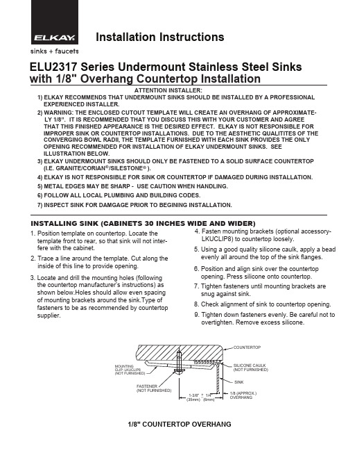
INSTALLING SINK (CABINETS 30 INCHES WIDE AND WIDER)ATTENTION INSTALLER:1. Position template on countertop. Locate thetemplate front to rear, so that sink will not inter- fere with the cabinet.2. Trace a line around the template. Cut along the inside of this line to provide opening.3. Locate and drill the mounting holes (following the countertop manufacturer’s instructions) as shown below.Holes should allow even spacing of mounting brackets around the sink.Type of fasteners to be as recommended by countertop supplier.4. Fasten mounting brackets (optional accessory- LKUCLIP8) to countertop loosely.5. Using a good quality silicone caulk, apply a bead evenly all around the top of the sink flanges.6. Position and align sink over the countertop opening. Press silicone onto countertop.7. Tighten fasteners until mounting brackets are snug against sink.8. Check alignment of sink to countertop opening.9. Tighten down fasteners evenly. Be careful not to overtighten. Remove excess silicone.1) ELKAY RECOMMENDS THAT UNDERMOUNT SINKS SHOULD BE INSTALLED BY A PROFESSIONAL EXPERIENCED INSTALLER.2) WARNING: THE ENCLOSED CUTOUT TEMPLATE WILL CREATE AN OVERHANG OF APPROXIMATE- LY 1/8”.IT IS RECOMMENDED THAT YOU DISCUSS THIS WITH YOUR CUSTOMER AND AGREE THAT THIS FINISHED APPEARANCE IS THE DESIRED EFFECT. ELKAY IS NOT RESPONSIBLE FOR IMPROPER SINK OR COUNTERTOP INSTALLATIONS. DUE TO THE AESTHETIC QUALITITES OF THE CONVERGING BOWL RADII, THE TEMPLATE FURNISHED WITH EACH SINK PROVIDES THE ONLY OPENING RECOMMENDED FOR INSTALLATION OF ELKAY UNDERMOUNT SINKS. SEE ILLUSTRATION BELOW.3) ELKAY UNDERMOUNT SINKS SHOULD ONLY BE FASTENED TO A SOLID SURFACE COUNTERTOP(I.E. GRANITE/CORIAN /SILESTONE ).®®4) ELKAY IS NOT RESPONSIBLE FOR SINK OR COUNTERTOP IF DAMAGED DURING INSTALLATION. 5) METAL EDGES MAY BE SHARP - USE CAUTION WHEN HANDLING. 6) FOLLOW ALL LOCAL PLUMBING AND BUILDING CODES.7) INSPECT SINK FOR DAMGAGE PRIOR TO BEGINING INSTALLATION.ELU2317 Series Undermount Stainless Steel Sinks with 1/8" Overhang Countertop Installation1/8" COUNTERTOP OVERHANGCAULK FURNISHED)SINK(APPROX.)MOUNTINGINSTALLING SINK (CABINETS 27 INCHES WIDE)5. Insert fasteners loosely, all around the sink.6. Using a good quality silicone caulk, apply a bead evenly all around the top of the sink flanges.7. Position and align sink under the countertop opening. Press silicone onto countertop.8. Tighten fasteners until the sink is snug against the countertop.9. Check alignment of sink to countertop opening.10. Tighten down fasteners evenly. Be careful not to overtighten. Remove excess silicone.1. Position template on countertop. Locate thetemplate front to rear and left to right, so that sink will not interfere with the cabinet.2. Trace a line around the template. Cut along the inside of this line to provide opening.3. Cut an opening in a sheet of plywood orunderlayment. The size of the opening should be the same as the one in the countertop.(Optional: Create a recess in the sheet in which the sink rim can sit. See graphics below.)4. Place the sink and plywood (or underlayment) under the countertop.PLYWOOD/UNDERLAYMENT OPTIONAL RECESS DIMENSIONS1/32 (.031”) MAXSuggestions for the Care and Cleaning of your Elkay Stainless Steel SinkELKAY SATIN FINISHElkay's original highlighted satin finish is produced by an abrasive grinding operation which lends a uniform pattern of satin finish lines to the metal surface. All exposed areas then undergo a series of progressive machine and hand polishing operations. It is this careful polishing that makes an Elkay satin luster finish so beautiful…and so easy to clean and maintain. RECOMMENDED CLEANSERSElkay has tested general household cleansers to mea-sure their effectiveness in cleaning stainless steel sinks. The most aggressive cleansers consist of Bar Keeper’s Friend, Zud and Lawrence Right Work. Other cleansers, which are still effective, but less aggressive include Ajax, Comet, Shiny Sinks Plus, Luneta, Soft Scrub, Mr. Clean, Maas and Flitz. So to help maintain the beautiful finish of your stainless steel sink, use one of the cleansers that Elkay recommends.RECOMMENDATIONSFOR PROPER MAINTENANCE•Do…Rinse thoroughly after each use. “Thorough”rinsing can be done by running water for a few min-utes and rubbing the cleaned area with a clean sponge.•Do…Towel dry after each use to prevent mineral deposits from building up on the surface of the sink.•Do…Clean the sink once a week, being sure to rub in the direction of the satin finish grain lines, using an Elkay recommended cleanser.•Do…Use an Elkay bottom grid or rinsing basket to “protect” the finish. Bottom grids and rinsing baskets can remain in the sink and will not cause rusting or pitting.•Do Not…Rub the sink across the satin finish lines. Scouring across the satin finish lines can damage the original sink finish.•Do Not…Allow soap or other household cleansers to dry on the surface of the sink. Most brands contain chemical additives which will affect the original finish.•Do Not…Use solutions of chlorine bleach and water in the sink. Chlorides, which are found in most soaps, detergents, bleaches, and cleansers, are very aggres-sive to stainless steel. If left on the sink too long they can cause surface pitting.•Do Not…Use a steel wool pad to clean your sink. If a more abrasive product is needed, use a green Scotch Brite pad being sure to rub in the direction of the satin finish grain lines. Steel wool pads have a tendency to break apart and small particles of steel can becomeembedded in the surface of the sink. The steel par-ticles will rust and will give the appearance that the sink itself is rusting.•Do Not…Use rubber mats or dishpans in the sink. Leaving rubber mats or dishpans in the sink can lead to surface rust or possible pitting. However, if you insist on using mats or dishpans, please remove them after each use and rinse thoroughly.•Do Not…Leave wet sponges, cloths, or cleaning pads on the sink. This can lead to surface rust.Following these recommendations for the care and cleaning of your stainless steel sink will insure that it will provide you with many years of service. CHLORIDESToday, chlorides are found in most all soap, detergents, bleaches and cleansers; chlorides can be aggressive to stainless steel. However, chlorides are very water solu-ble. Therefore, THOROUGH RINSING of your sink after each use to remove any chloride residue and a weekly cleaning is all that is required to keep your sink looking bright and shiny.SCRATCHESLike many metallic surfaces, your stainless steel sink will scratch. These are merely usage scratches and over time will blend into the overall finish of your sink with proper cleaning.KNIVESYour sink is designed to serve as many things but not as a cutting board or chopping block. This type of use will lead to deep scratches in the sink finish and will dull your knives. Elkay does offer various cutting boards which will provide an additional work area.WATER QUALITYThe quality of your water can affect your sink’s appear-ance. If your water has a high iron content, a brown sur-face stain can form on the sink giving the appearance of rust. Additionally, in areas with a high concentration of minerals, or with over-softened water, a white film may develop on the sink. To combat these problems, we suggest that the sink be towel dried after use, and again, on a weekly basis, the sink should be cleaned using a recommended cleanser.FOODSHeavy salt concentration or foods containing high levels of salt should not be allowed to dry on the sink surface. Rinse your sink thoroughly after use.Elkay2222 Camden Court Oak Brook, IL 60523©2010 ElkayPrinted in U.S.A.(Rev. RL 5/10) PART NO. 74180688 ELKAY LIMITED LIFETIME SINK WARRANTYElkay warrants to the original purchaser of an Elkay stainless steel sink that Elkay will,at its option,replace or repair,without charge,such product if it fails due to a manufacturing defect for a lifetime of normal residential use. Product replacement does not include transportation cost or labor installa-tion cost.This warranty covers only stainless steel self-rimming drop-in sinks installed in a conventional countertop surface and stainless steel under-mount sinks installed in a conventional solid surface countertop and applies to residential installations only.Elkay reserves the right to examine product in question and its installation prior to replacement.WASTE FITTINGS AND ACCESSORIES ARE NOT WARRANTED OTHER WARRANTY CONDITIONS ON SINKSThis warranty applies to sinks purchased after March1st2001as shown on the purchaser’s dated receipt.For sinks purchased prior to March1st2001, the applicable warranty at that time will be in effect.Our warranty does not cover product failure or damage caused by the use of optional Elkay acces-sories,abusive treatment,misuse,environmental factors,normal wear including dents and scratches,improper care and cleaning,use of aggres-sive and abrasive cleaners,damage due to handling or failure to follow the recommended procedures for installation,care and maintenance as detailed in the installation and care guide provided with every sink.This warranty is extended only to the original consumer purchaser of the product.This war-ranty does not cover shipping costs,labor costs,or any other charges for such items as installation or replacement of the sink,diagnosis or replace-ment of any faucet or component part,or any other expense or loss.All incidental or consequential damages are specifically excluded.No additional warranties,express or implied are given,including but not limited to,any implied warranty of merchantability or fitness for a par-ticular purpose.Some states do not allow the exclusion or limitation of incidental or conse-quential damages or limitations on how long an implied warranty lasts,so the above limitations or exclusions may not apply to you.This warranty gives you specific legal rights,and you may also have other rights which vary from state to state.TO OBTAIN SERVICE UNDER WARRANTY1.Write to:Elkay Manufacturing CompanyAttention:Consumer Services2222Camden CourtOak Brook,IL605232.Include a letter containing the following information:a.Date of purchase and installationb.Proof of Purchase(copy of original dated invoice)c.Description of nature of defectd.Model number or description of model and/or component part ifpossible.。
中英文安装说明书

Enclosure Climate Control Unit工业控制柜制冷机Assembly Instructions安装说明书(ECC 系列)内容1.应用场合2.技术参数3.安装方式4.安全与注意5.电气连接6.常规操作7.工作原理8.维护保养9.质量保证10.电气原理图11.安装尺寸图1.应用场合工业控制柜制冷机通过把控制柜的空气冷却同时把柜内热量驱散出柜外,从而保护控制柜内的电气元件在可控的范围内运行。
制冷机同时具有除湿功能,保证控制柜内有理想的温度和湿度。
2.技术参数壁装系列型号 ECC225ECC320 ECC680 ECC825设计电压VAC/ Hz230/50可用制冷功率W(L35 L30)225 320 680 825外形尺寸(H×W×D)mm445×286×181 630×350×190 制冷剂 R134a环境温度/可调节范围(℃) 20~55 / 20~38重量(Kg) 15 16 26 28型号 ECC1100ECC1500设计电压VAC/ Hz230/50可用制冷功率W(L35 L30)1100 1500外形尺寸(H×W×D)mm400×1000×240制冷剂 R134a环境温度/可调节范围(℃) 20~55 / 20~38重量(Kg) 38 41顶装系列型号 ECC680T ECC1100T ECC1500T设计电压VAC /Hz230/50可用制冷功率W680 1100 1500外形尺寸(H×W×D)mm350×527×335 410×608×427制冷剂 R134a R22环境温度/可调节范围(℃) 20~55 / 20~38重量(Kg) 26 36 403.安装方式根据产品的型号,制冷机可以有壁装,顶装,两种安装方式,开孔图详见下面的安装尺寸图3.1外挂式按照开孔图开孔,把相应型号的制冷机用随附的螺钉先安装到控制柜上,使用制冷机后面的内六角螺钉与控制柜锁紧。
- 1、下载文档前请自行甄别文档内容的完整性,平台不提供额外的编辑、内容补充、找答案等附加服务。
- 2、"仅部分预览"的文档,不可在线预览部分如存在完整性等问题,可反馈申请退款(可完整预览的文档不适用该条件!)。
- 3、如文档侵犯您的权益,请联系客服反馈,我们会尽快为您处理(人工客服工作时间:9:00-18:30)。
· ·
· ·
ODEON
( ) 4mm/m
13-1
528437
1062843-T01-B
1
ã
C
, 2008 Copyright Kohler China Ltd., 2008
2005/2/25 13
ROUGHING-IN
Colors/Finishes
B B
/
0 White 0 SHP Polished Silver SHP 抛光亮银 Roughing-In Notes A K-17116T-L-0 1850mm K-17116T-L-SHP Note: Max. door opening is 500mm 500mm B 872mm+7.5mm -
A
UNIT: mm
B
B
46.5mm
25mm
Elevation Plan view
1062843-T01-B
2
2005/2/25 13
INSTALLATION REQUIREMENTS
Tools Required
Phillips Screwdriver Pencil Caulk Gun Measuring Tape Safety Glasses Center Punch Hammer Knife Drill & 6mm Drilll Bit, 3.6mm Regnlar Bit Level
Wall Mounting Screw
2.
6 ST4.2 x 28
ST4.2x28
Wall Jamb
B
Shower Receptor
1062843-T01-B
5
3.Install The Bottom Rail
Install the bottom rail into the wall jamb on the receptor. Note:Make sure there are seals in each end of the top and bottom rails,and the end of the seal aligns with the end of the rail.
3. 安装下导轨
取一支导轨,将其两头插入墙边柱放在盆沿上。 注意:检查确保轨道内两端都有封条,并且边缘和导轨边缘平齐。
B
4. Install The Infill Glass
Press fit the infill glass to the bottom rail. Note:Make sure that the fixing holes in the glass align with the holes in the bottom rail. Make sure the glass infill panel aligns with the end of the rail.
Pencil
Level Wall Jamb Inside
B
C
Outside Wall Jamb
1.
C ( (
Shower Receptor
Dimension C for receptor = 862 C=862
20mm
) )
2. Installing Wall Jambs
Install each wall jamb by aligning the holes in the wall jambs with the holes in the wall. Secure the wall jambs with 6 ST4.2 x 28 screws provided.
NATEO
INSTALLATION INSTRUCTIONS ROUND SLIDING DOOR K-17116T
BEFORE YOU BEGIN
· Before you install your shower door, please read these instructions carefully to familiarize yourself with the required tools, materials, and installation sequences. Follow the sections that pertain to your particular installation. This will help you avoid costly mistakes. In addition to proper installation, read all operating and safety instructions. · These instructions contain important care, cleaning, and warranty information-please leave these instructions for the consumer. · Instructions, drawings, and diagrams contained in this manual present information available at the time of printing. Although every attempt has been made to keep them up-to-date, Kohler Company reserves the right to implement product changes without further notice. · Make sure that the bath and the finished wall material are completely installed prior to installing your ODEON. · While most illustrations depict ON FLOOR installation, and where ever possible, illustrations showing specific requirements for each option are given. Where not, dimensions relating to each are included. CAUTION: Risk of injury or product damage. Tempered glass cannot be cut. CAUTION: Before commencing installation, KOHLER strongly recommends reading this manual. ATTENTION: Please install this door on Kohler corner. IMPORTANT: The shower door requires a flat vertical finished wall. The squareness of the wall is recommended no more than 4 mm/m. KOHLER Company won t take responsibility of the installation quality. ·
6mm
3.6mm
Materials Required
Drop Cloth Silicone Sealant
1062843-T01-B
3
1062843-T01-B
1. Marking and Drilling Wall Jamb Mounting Holes
Measure and mark on the receptor ledge near the wall, dimension "C" out from the back wall. Align outside edge of wall jamb with the mark made on the receptor ledge. Using a level, plumb the wall jamb and mark the three wall mounting holes with a pencil. With a center punch, lightly punch the three hole locations for the wall jamb. (On ceramic tile, use a center punch to nick the surface glaze.) Tap the punch lightly with hammer so as not to crack tile. Use a 6mm drill bit (a masonry bit for ceramic tile). After drilling, thoroughly clean the receptor edge and wall. Insert plastic anchors in all three holes. Repeat procedure for the other wall jamb. NOTE: Wear Safety Glasses.
5. 安装上导轨
按压顶部导轨两侧,使其卡入固定扇玻璃。 注意:确保固定扇玻璃与导轨边缘对齐,确保轨道孔和玻 璃孔对齐。
B
6.Adjust The Top Rail
To make sure that the rails are correctly fitted to the glass infill panels use a tape measure to make sure that the total height of the assembled product is 1850mm. If higher or lower, try pressing the top rail onto the glass infill panels harder, or insert a wedge into the gap between infill glass and the seal in rail.