ZJ70D机固控系统说明书(肯尼亚)
70D钻机的安装与调试
70D钻机的安装与调试 WORD文档使用说明:70D钻机的安装与调试来源于本WOED文件是采用在线转换功能下载而来,因此在排版和显示效果方面可能不能满足您的应用需求。
如果需要查看原版WOED文件,请访问这里70D钻机的安装与调试|PDF转换成WROD_PDF阅读器下载重庆钻井工程公司操作与保养规程ZJ70D 型钻机西南石油局重庆钻井工程公司装备科编制二00三年一月操作与保养规程ZJ70D 型钻机目录第一章钻机的安装与调试第一节钻机的安装第二节钻机的调试第三节钻机的起升第二章钻机的使用与维护保养第一节警示第二节钻机使用注意事项第三节操作与维护保养规程第三章钻机的拆卸与运输第一节钻机的下放第二节钻机的拆卸第三节钻机的运输ZJ70D 型钻机操作与保养规程第一章钻机的安装与调试第一节钻机的安装一.机安装及操作人员应先熟悉钻机总体、配套及各部件结构特性、重量尺寸等,仔细阅读使用说明书,明确要求和规定,作好各项前期准备工作。
二.安装工具安装钻机时需准备的测量工具:刚卷尺、水平尺、百分表、线绳、铅垂。
钻机随机携带有一套钻机安装和调试用的工具,如撬杠、搬手、管钳、大锤、手锤、干油站等及吊装用绳索。
三.钻机基础按钻机说明书附图3―1 基础图要求建造钢精混凝土基础梁。
钻机主要设4-1操作与保养规程ZJ70D 型钻机备的基础坑应设置在挖方上,若设置在填方上要进行技术处理,基坑耐压强度应不小于 2MPa,基础平面度误差不大于 3mm。
四.机的安装钻机主要部件之间的安装顺序应基本符合下述方框图的规定:井架天车游车大钩穿大绳底座绞车转盘驱动装置发电房气源房电控房钻井泵起升井架起升底座滑道提升机坡道猫道校正井口在保证安全、场地允许的情况下,方框图以外的辅助设备可以交叉安装。
(一)钻台区部分 1、底座的安装(详见DZ450/10. 5―S1 底座《使用说明书》)注意:出后台梯子外,坡道、梯子、紧急滑道及上固控罐梯子等均在底座起升后安装。
ZJ70DB司钻操作触摸屏使用手册
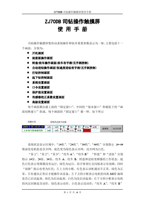
ZJ70DB司钻操作触摸屏使用手册司钻操作触摸屏集传动系统操作和钻井重要参数显示为一体,主要包括十一个画面。
分别为:●开机画面●泥浆泵操作画面●转盘/绞车操作画面(绞车有手柄/无手柄控制)●自动送钻操作画面(恒速度送钻有手柄/无手柄控制)●打钻控制画面●起下钻控制画面●系统设置画面●口令设置画面●保护值设置画面●传感器校正系数设置画面●高级设置画面每个画面都由最上面的“固定窗口”、中间的“基本窗口”和最低下的“画面切换窗口”组成。
每个画面的“固定窗口”都一样,如下所示系统状态显示区域中,“1#机”、“2#机”、“3#机”、“4#机”分别指示1#~4#柴油发电机组是否并网,底色变为绿色表示并网,没并网为白色。
“泵1”、“泵2”、“泵3”、“绞车A”、“绞车B”“转盘”和“送钻”分别指示1#泵、2#泵、3#泵、绞车A、绞车B、转盘和送钻变频器的工作状态,底色白色表示变频器没有运行,绿色为运行,而字体变红且闪烁表示有故障,同时“故障”指示也变为红色;左上方的小框,红色表示该柜通讯不正常,绿色为正常,只有通讯正常后才能操作该设备;左下方的小框表示电机的风机MCC抽屉是否已启动起来,绿色为启动起来,白色为没启动起来;右下方的小框表示电机的风压回路是否动作,绿色表示动作,白色表示没动作;“绞车A”、“绞车B”和“送钻”的右上方小框表示离合器状态,粉红色表示没挂合,绿色表示挂合。
“安全钳”由红色变为绿色表示电控系统已发出安全钳打开指令。
1.开机画面:当给触摸屏送电后或在其它画面点击按钮,进入该画面。
2.泥浆泵操作画面:点击按钮进入。
2.1 1#泥浆泵的操作:首先通过快速回零键将给定回零,这时触摸操作屏上的“快速回零”键变黄,然后按下“1#泥浆泵启/停”按钮,使其变绿,若系统正常,则触摸屏固定窗口上的“泵1”底色变绿,通过快增键(每按一次增加10spm)、慢增键(每按一次增加1spm)、快减键(每按一次减少10spm)和慢增键(每按一次减小1spm)调整给定(0~120spm),使1#泵按给定的泵冲开始工作。
ZJD钻机固控系统说明书肯尼亚

一、安全事项1.安全预防2.安全标记和警示3.注意事项①安全规定1)各岗位工作人员必须经过培训持证上岗;2)操作人员要懂设备的操作、保养和安全规程并明白相关的注意事项;3)操作人员要具备良好的身体状况,身体不适时,不得上岗。
②安全装置1)所有电器设备、照明器具及输电线路具备防火、防爆功能;2)保护装置要拧紧、完好、有效;3)正确使用安全装置:护栏、梯子等;4)不准随意拆卸安全装置。
③个人保护用品1)操作系统设备时必须佩带劳保;2)劳保产品的防护性能要达到防护要求。
二、固控系统说明1.固控系统简介ZJ70D钻机固控系统配备有振动筛、真空除气器、钻井液清洁器等四级净化装置以及6个钻井液罐、1个冷却水罐、1个组合补给罐、1个泥浆冷却罐。
具有高架管路(从井口至振动筛),钻井泵抽吸管路、加重泵抽吸及排出管路、清水管路、中压钻井液泥浆枪管路、罐底连通管路等各种管汇。
系统还配有钻井液补给系统、加重漏斗、加重泵、除砂供液泵、除泥供液泵、补给泵、搅拌器等辅助设备。
另外,还配有走道、梯子、栏杆等安全防护装置。
本套固控系统能够保证泥浆的净化、循环、配制、加重和储备等工作顺利进行,还具备增强了钻井液净化系统的固相控制能力,能满足7000m钻井工艺的要求。
2.固控系统组成与结构特点本套固控系统由6个钻井液罐组成,总容积为380立方米3。
固控系统配四级净化装置,配1台三联振动筛、1台真空除气器、1台钻井液清洁器及砂泵、混合加重装置等。
本套固控系统的设计符合总体设计要求、钻机平面布置和标准的钻井液处理工艺流程,钻井液调配方便,拆装移运简便快捷。
整个固控系统具有以下结构特点:(1)具有比较先进的工艺流程(2)各种设备阀门操作简单方便3.系统技术参数及设备技术参数(1)系统技术参数①总容积:380m3;②总有效容积:300m3;③泥浆罐数量:主罐6个,组合补给罐1个,冷却水罐1个,泥浆冷却罐1个;④系统设计最大处理量为360 m3/h ;⑤钻井液配置能力为400m3/h;⑥适用钻井液密度<2.5×103㎏/m3;⑦水管线额定工作压力:0.6MPa;⑧中压泥浆枪管线额定工作压力: 6.4MPa;⑨工作环境温度:-18℃-+55℃;⑩装机总功率:620KW;○11各主要管线规格:井口溢流管DN300(12")罐间泥浆槽连通管DN300(12")罐间底连通管DN250(10")钻井泵吸入管DN300(12")泥浆枪管线连通管DN80(3")清水管线连通胶管DN80(3") (2)系统主要配套设备性能参数(见表1)(3)钻井液罐参数及设备布置①钻井液罐参数(见表2)②钻井液罐设备布置(见平面布置图)设备性能参数表(表1)钻井液罐技术参数表(表2)4.固控系统原理与工艺流程1)原理:配制好的泥浆在钻井泵的作用下进入井底并携带钻屑返回地面,经过井口接管和分配器进入振动筛,经过振动筛、真空除气器、钻井液清洁器器,完成钻井液的四级净化。
ZJ70D58钻机使用手册英文版

CNPCZJ70/4500D Drilling Rig Operational ManualAZ702158-00SMJune, 20072PREFACE (5)1.G ENARAL INTRODUCTION (6)1.1U SE AND F EATURES (6)1.2D ESIGN AND M ANUFACTURE S TANDARDS OF D RILLING R IG ZJ70/4500D (7)1.3T ECHNICAL P ARAMETERS OF D RILLING R IG (7)1.4I NTRODUCTION TO G ENERAL D ISPOSAL AND D RIVE OF D RILLING R IG (9)2.COMPONENTS AND MATCHING SYSTEMS OF THE DRILLING RIG (13)2.1JC-70D D RAWWORKS (13)2.2R OTARY T ABLE D RIVING D EVICE (29)2.3C ROWN B LOCK TC7-450 (33)2.4T RAVELING B LOCK YC-450 (35)2.5H OOK DG-450 (36)2.6R OTARY S WIVEL SL-450 (38)2.7M AST JJ450/45-K14 (43)2.8S UBSTRUCTURE DZ450/10.5-X11 (48)2.9P NEUMATIC S YSTEM (49)2.10I NSTRUMENT S YSTEM (57)2.11W ELL H EAD M ECHANIZATION I NSTRUMENTS (58)2.12F-1600P UMP UNIT (60)2.13P RESSURE M ANIFOLD (61)2.14P OWER S YSTEM (61)2.15E LECTRIC D RIVE C ONTROL S YSTEM (67)3.I NSTALLATION AND C OMMISSIONING OF THE D RILLING R IG (70)3.1P REPARATION BEFORE I NSTALLATION (70)3.2F OUNDATION OF THE D RILLING R IG (71)3.3I NSTALLATION (73)3.4T HE C OMPONENTS I NSTALLED AFTER THE J ACK-UP OF THE M AST AND THE S UBSTRUCTURE (77)3.5C HECK AFTER THE I NSTALLATION OF THE D RILLING R IG (78)3.6C OMMISSIONING OF THE D RILLING R IG (79)3.7J ACK-UP OF D RILLING R IG (84)4. USE OF THE DRILLING RIG (85)4.1W ARNING (85)35. DISASSEMBLY AND TRANSPORTATION (87)5.1L OWER DOWN DRILLING RIG (87)5.2D ISASSEMBLY OF THE D RILLING R IG (88)5.3T RANSPORTATION OF THE D RILLING R IG (88)6. DRIVE PARTS LISTS (89)6.1B EARING L IST (89)6.2C HAINS AND B ELTS ON THE D RILLING R IG (91)4Drilling rig ZJ70/4500D is designed and manufactured by Baoji Oilfield Machinery Co., Ltd accoridng to the user’s requirement, the “Technical Agreement of Drilling Rig ZJ70/4500D”, the criteria in “Oil Drilling Rig Type and Basic Parameters” ZJ70/4500D and the related regulations in API, which can meet the requirement of the exploration and development of deep well oil and natural gas well.This Operation Manual provides an overall introduction of the drilling rig for the related operators to know and master the use of this drilling rig. There is a lot of matching material of the drilling rig, so this Operation Manual only gives the explanation for the components of the main machines and the necessary and brief introduction for the devices and parts prepared by the users themselves.For the structral parameters and maintenance items of the matching equipment or parts, which are needed in the use, please see the Operation Manual and other related techinical documents for reference.Before the use of the drilling rig, the concerned administrators, technicians and operators must read this manual and the related manuals and materials of the substructure carefully, knowing and mastering all the details besides acquiring the related knowledge and skills of the safety operation.All the administration and specific operation should be conducted according to the rules and regulations of our system and unit.According to the feedback information or the requirement for the techincal improvement or update from the the service people, we can change the types, parameters and the structures of the product at any time. We will not inform before or after the change, nor will we bear any responsibility or obligation for this.Complete technical documents are attached with the drilling rig, providing the directive information of management, installation, use and maintenance for the purchasers and the users. Nobody is allowed to copy them in any way, nor to provide them to the third party. Otherwise, he should take the legal responsibility for the consequence.5Drilling rig ZJ70D is an SCR direct current driving drilling rig, which is to meet the requirement of the exploration and development of oilfield deep well drilling. The drilling rig’s basic parameters are in accordance with China SY/T5609 Standards, the main matching components in accordance with the API regulations; the drilling rig is able to meet the requirement of the new drilling techiniques; it is safe and reliable. Its main technical capacities have achieved the international advanced level among its contemporary counterparts. The drilling rig can also be equipped with the top drive drilling device.Technical and Structural Features of Drilling Rig ZJ70D:1) The AC-SCR-DC one-to-two completely numerical control electric drive power system is adopted; the drawworks, the rotary table and the mud pump can be stepless speed regulated, acquiring the good drilling features, with steady start, highly efficient drive and automatic even allocation of the load.2) The mature advanced techniques and structures both abroad and at home are adopted; the requirement of the standards are also noticed so that the advancement, the reliability and the standardization are further enhanced.3) It is designed in combination and modularization: the drilling rig is set in good order; the number of the equipment blocks is small; it is convenient to be moved and installed. Meanwhile, it is more interchangable, providing the choice requirement of different users.4) The platform equipment and the low-position installation of the mast can be wholly jacked up with the winch drive, which is convenient and time-saving for the installation.5) The drilling rig is completely and perfectly equipped and is able to meet the different requirements for the deep well drilling in different places and environments.6) The drilling rig is equipped with the hydraulic disc brake and drilling control room, which makes the drilling not only safer, more reliable and comfortable, but also evener and more accurate, enhancing the drilling efficiency.7) The rotary table is adopted with the independent drive, raising the flexibility of the drilling rig; the rotary table driving box is set with two gears to meet different requirements in different working conditions, raising drilling efficiency.6technics. The system is easy to move and the tank surface is flatened to meet the requirement of HSE.9) It is in the need of the international and domestic drilling market, meeting requirements for the new drilling techiniques. It is able to work regularly in the ambient temperature -20°C~+50°C, relative huimidity ≤90% (+20°C), and other bad conditions.1.2 Design and Manufacture Standards of Drilling Rig ZJ70/4500D1)API Spec Q1 “Quality Compedium regulations”2)SY/T5609-1999 “Oil Drilling Rig Form and Basic Parameters”3)API Spec 4F “Regulations for Drilling and Repairing of Mast and substructure”4)API Spec 8A 8C “Regulations for Jacking Equipment of Drilling and Exploitating”5)API Spec 7K “Regulations for Rotating Drilling Equipment”6)API Spec 7F “Transmtiting Roller Chain of the Drilling Rig”7)API Spec 9A “Regulaitons for Wire Line”8)API spec 16C “Regulations for Throttle and Killing Well Device”9)AWS D1.1 “Regulations for Welding Steel Structure”10)API spec 9A “Regulations for Wire Line”11)API RP 53 “Recommended Practice in Designing Drilling Control Equipment withControl System”12)API spec 16D “Regulations for Drilling Control System”13)AISC “Specifications for structural steel buildings”1.3 Technical Parameters of Drilling Rig1) Nominal Drilling Depth Scale: Ф127mm(5”)Drilling pipe 4000-6000mФ114mm(4 1/2″)Drilling pipe 4500-7000m Max Hook Load 4500kN2) Drawworks Rated Power 1470kW(2000HP)Drawworks Gear Number 4+4R Direct current drive, stepless speedMain Brake Hydraulic Disc BrakeAuxiliary Brake DWS70 Water cooling electromagnetic brake78Pulley outside Diameter of hoisting SystemФ1524mm(60”) 4) Central Pipe Drift Diameter of Swivel Ф75mm5)Type and Number of Drilling Pump2 pumps; F-1600 6) Norminal Diameter of Rotary Table MouthФ952.5mm (37 1/2”) Gear Numbers of Rotary Table 2+2R (independent drive) Steplessspeed regulated 7) Mast Type and HeightFront mouth, 45.5m 8) Substructure TypeSwing Lift (string the rope once; jack up continuously) Drilling Table Height10.5m Drilling Table Area13.935m×13m Bottom Height of Drilling Table Girder9m 9) Power tranmission TypeAC-SCR-DC 10) Diesel generating setCAT3512 Diesel Engine No.×Main Power 3×1330bkWRotating speed of Diesel Engine1500r/min Type of GeneratorSR4B Parameters of Generator1900KVA, 600V , 50Hz Power Submultiples0.7 non-brush excitation 11) Auxiliary Generating SetCAT3406/SR4 No.×Power1×365kVA,1500r/min ,400V/230V , 50Hz, 3-phase 4-line 12) No. of Direct Current Electromotors×Power7×800kW (Independent Drive) Rated Rotating Speed970r/min Voltage750V ,DC Current1150A 13) Electric Drive SystemControl Unit of Controllable Sillicon one-to-twocontrol 5 cabinetsOutput Current 1850A, DC (rated)MCC System 600V/400V(3 phase)/230V (single phase),50Hz 14)Drilling Fluid Pipe Manifold Ф103mm×35MPaStandpipe Ф103mm×35MPa,double Standpipe15) well control system F54-14, F35-70 BOP unit16) Mud Tank 6 Tanks total capacity: 350m317)Air receiver (2.5+4)m3, (with check valve and other accessories)Air Source Pressure 1MPa18)Diesel Tank 45m3 +55m319) Industrial Water Tank Nested water tank 100m3, cool water tank 40m320)Appliable Environment:Temperature: -20~+55°CHumidity: ≤90%Wind Speed: ≤110km/hOil Field1.4 Introduction to General Disposal and Drive of Drilling Rig1) The main power of the drilling rig is 3 diesel generating sets of CAT3512 1500KVA or CAT3512B 1900KVA, outputting 600V, 50Hz alternating currunt, which is changed into 0-750V direct current through rectification of SCR cabinet, driving respectively the 2000HP drawworks, the rotary table and the YZC08/YZC08A series excitation direct current electromotor of the mud pump; the rotary table is independently driven. The drawworks is driven by two eletromotors; the rotary table is independently driven by one electromotor; the two mud pumps are driven respectively by two electromotors. The electric drive system is controlled in one-to-two model and AC-SCR-DC drive.2) The front open mast and the new one-jack swing lift substructure are once together jacked up to the working place by the drawworks power; the mast and the substructure are once strung; all the equipment is installed at low position.3) Main brake of the drawworks is a hydraulic disc brake and auxiliary brake is water9requirement of the driiling project and the assembly, disassembly and maintenance of equipment.5) The drilling rig consists of six zones: the drilling floor zone, the pump room zone, the power zone, the mud circulation and water tank zone, the oil tank zone, the oilfield room zone.* The drilling floor zone includes the mast, the substructure, the drawworks, the rotary table, the hoisting system, the wellhead mechnization equipment and tool, the drilling floor dog house, the drilling pipe sliding board and shelf, elevator and other equipment.The drilling floor is equipped with two 50KN pneumatic winches.The drilling floor is equipped with two dog houses with the dimensions of 10000×2800×2800 mm, the back pry size is length×width 2400×250mm.The mechanization tools on the drilling table:a. Make-up spinning hydraulic cathead YM-16 Max Pull 160kNb. Break-down spinning hydraulic cathead YM-16 Max Pull 160kNc. HPU (on the front end of the left dog house) Rated pressure 16.6MpaThe height of the catwalk and the drilling pipe racking is 1070mm; a drilling pipe buffering device and a 50kN air winch are equipped on the catwalk.* Pump room zone: is disposed with 3 F-1600 mud pumps set, drilling hydraulic pipe manifold, etc.* Power region: Four diesel generator unit rooms (including auxiliary generator, two air compressors, one set of pneumatic supply purification device) are parallel distributed to form an integrated machine room; and SCR (MCC) room and machine unit are vertically leaned against each other. The well center with the left end of SCR room is about 34m.* Mud circulation and water tank region: It includes mud circulation tank, mud purification device and water tank, etc.* Oil tank: includes different types of oil cylinders, pumps and pipelines.The connecting pipelines of oil, gas, water and electricity between different zones are10Drawing 1-1 Elevation Drawing of Drilling Rig ZJ70D11Drawing 1-2 Drilling Rig ZJ70D Floorplan12Drawing 1-3 Schematic Diagram of Drilling Rig Drive2 Components and Matching Systems of the Drilling RigDrilling rig ZJ70/4500D is a direct current driving drilling rig, used for the deep well drilling. Its main matching components are designed and manufactured according to the related regulations of API, and therefore can meet the related requirements of HSE.2.1 JC-70D DrawworksDrawworks drive JC-70D is part of the drive system of the Drilling Rig ZJ70D. The drawworks is not only used for making a trip, running the casing, controlling the weight on bit, dealing with the accident, lifting the core container, testing for oil, but also used for jacking and lowering of the mast and substructure. It is composed of two parts: the power device (including the input shaft) and the drawworks body. See drawing 2-1.Drawworks JC70D has the following features:1) Large powerThe drawworks is driven by two YZ08 electromotors (made in China), and parallel operated through the input axis of the power device. The rated input power can reach 1470kW.2) Good capability of speed adjustment and high efficiency of power13gears are also formed through the high speed and low speed clutches between the drive axis and the roller shaft. The winch has altogether 4 forward and 4 backward gears. Due to the adoption of the direct current electromotor, the winch can realize the step-less speed regulation, which greatly enhances the power utility and saves the hoist time, raising the work efficiency.3) The hydraulic disc brake is adopted. Its braking moment is large, and it is safe and reliable. It can exactly adjust and control drilling pressure, send drilling evenly; and control the putting down speed during drilling process. It is equipped with water-cooled eddy current brake at same time, which increases reliability of the drawworks.144) Advanced control and ic control system, which is simple and e Parameters1470kWlaborsaving operationThe drawworks is adopted with electro-hydraul reliable. The control handle, the brake, the drilling parameters, the instruments and so on are all concentrated in the driller control room, so it is very convenient to operate.The drawworks is also characteristic for its simple drive, compact structure, large scal of speed shift, high efficiency, long service life, safety and reliability, and the neat appearance.2.1.1 Technical 1) Rated input power 2) Max fast line pull485kN 15165) Size of slotted roller (diameter×length)Φ770×1310mm 6) Size of brake disc (outer diameter×thickness)Φ1650×76mm7) Overall DimensionsDrawworks bodyJC -70D 7520×3250×3216mm Power set6400×1580×1876mm 8) WeightDrawworks body45785kg Power device12460kg 9) Hook load and speed list of the gears Traveling system 6×7 Gear Roller speed(r/min) Hook speed(m/s) Hook load (kN) Fast line pull (kN) Cathead speed (r/min) Ⅰ0~78 0~0.33 0~4500 0~487 Ⅱ0~120 0~0.52 0~2800 0~303 Ⅲ0~217 0~0.91 0~1600 0~173 Ⅳ 0~336 0~1.58 0~1000 0~108 0~159 0~2762.1.2 Drive PrinciplesThe drive flow chart of drawworks JC-70D is shown in Drawing 2-2.The drawworks is of four-shaft structure, consisting of the input shaft, the drive shaft, the cathead shaft, and the drum shaft.Two YZ08 electro motors are in parallel operation through the input shaft of the power device. The integrated power forms two gears through two chains between the input shaft and the drive shaft, and another two gears through two chains between the drive shaft and the drum shaft. So the drawworks has 2×2 gears in all. Besides, through the drive of one chain of the cathead shaft, the drive shaft makes the cathead shaft form two gears.It is the mechanical shift between the power input shaft and the drive shaft, and is the pneumatic tube clutch between the drive shaft and the drum shaft.gearshift, the drawworks must be stopped.The drawworks drive chains, which are in force feed lubrication, are equipped with the brake disk circulatory water cooling and water cooling electromagnetic vortex brake device. Functionally speaking, the drive of drawworks JC-70D is mainly composed of the following parts: see drawing 2-31) Drive part: imports, allocates and transmits the power, mainly including the assemblies of the input shaft, the drive shaft, the bailing drum shaft and the drum shaft, and the drive chains.2) Lifting part: is used for jacking up and lowering down the mast and the drilling floor, tripping in or out, running the casing, hoisting the load, making-up and shackling, etc.,178-bailing drum brake5) Brakeage system: is used to control the trip speed and the brake, mainly including the main brake and the auxiliary brake. The main brake of drawworks JC-70D is hydraulic tong disc brake, and the auxiliary brake is water cooling electromagnetic vortex auxiliary brake.6) Support part: is used for installing and fixing the components and parts of the drawworks, mainly including the substructure, the support and the guard.18electromagnetic vortex auxiliary brake, the anti-collision crown block device, the main brake system, the electric control system and the lubrication system.2.1.4 Main Brake System of the drawworksThe main brake system of JC-70D is adopted with the hydraulic disk brake.The hydraulic disc brake system consists of the part of the hydraulic control and the part of the hydraulic brake tong. The part of the hydraulic control, which is made up of a hydraulic pump station and an operation table, is the power source and the power control system, providing the necessary hydraulic pressure for the brake tong. The brake tong is the power executive system, providing the adjustable positive pressure for the main machine to accomplish the braking. The brake tongs include the work tongs and the safety tongs.Compared with the traditional belt brake, the hydraulic disk brake is characteristic for its large capacity of the brake torque, the steady effect of the brake, the small inertia of the brake secondary movement, the good adjustability of the brake force, the accuracy and flexibility of the brake and the convenience of the operation and the maintenance. The hydraulic system is safe for use with the simple and compact structure, the reasonable disposal and the reliable capability.2.1.4.1 Major Technical Parametersz Hydraulic control system19oil L-HM 20 for winter; N46 for summer)3) Rated flux for single pump 18L/min4) Volume of oil cylinder 80L5) Power of electrical motor 2×2.2kW6) Capacity of accumulator 4×6.3L7) Power of electric heating 1 KW8) Flux of cooling water 2m2/h9) Volume (length × width × height) 1160×960×1220 (mm)10) Weight 650kgz Normally open work tong1) Max positive pressure on single side N=75kN2) Effective working area of the piston A=12271.8mm23) Overall dimensions (outside diameter × length) φ165×380(max) (mm)4) Weight 210kgz Normally close safety tong1) Max positive pressure on single side N=75kN2) Max working gap of brake block δ≤1mm3) Effective working area of the piston A=12644.9mm24) Overall dimensions (outer diameter× length) φ230×420(max) mm5) Weight 235kg2.1.4.2 Working PrinciplesWork brake: control the positive pressure of the work tong on the brake disk through operated the control handle of the brake valve so as to provide an adjustable brake torque for the main machine, realizing the bit feed, adjusting the weight on bit and the speed of the trip.Emergency brake: in the emergency, press the red emergency brake button; all the work tongs and the safety tongs should get involved in the brake to realize the emergent brake. During the regular trip, this button is forbidden to press.Over-wind protection: when the load is hoisted to a certain position by the hook, but20emergency brake to prevent the collision with the crown block.Parking brake: when the drilling rig does not work or the driller is about to leave the work platform, pull down the parking brake handle, the safety tong brakes to prevent the slippery of the hook.See “Operation Manual of hydraulic disc brake device” for further information.2.1.5 Auxiliary Brake systemAuxiliary brake mechanism adopts DWS70 water cooling electromagnetic eddy current brake.Electromagnetic eddy current brake is a new type of auxiliary brake adapting to drilling rigs in ocean or on land, which utilizes electromagnetic induction principle to make brake without wearing. And this brake has the characteristics of large moment, long life span and simple operation and maintenance. Electromagnetic eddy current brake may decrease wearing of main brake greatly, lengthen the life spam of brake disc, and reduce labor intensity of drilling workers. During drilling, main brake is not used; the brake moment is adjusted only by changing magnetizing current to control the speed of placing down drill pipe. When the rotational speed slows down to 50 r/min, 75% of the maximum moment can be got, which can meet the demands of placing down drill pipe with heavy load.Technical parametersz Mode DWS70z Rated brake moment 110000N.mz Maximum magnetizing power 23kWz Weight 11000kg2.1.6 Anti-collision Crown Block DeviceThe function of the anti-collision device is that when the traveling system is hoisted to the limitative position, the emergency brake will stop the hoist of the traveling system through the caging device to prevent the collision with the crown block and guarantee the safety. There are three insurance systems for the anti-collision device of ZJ70D series drilling rigs. One is the wire line anti-collision device installed on a point of the upper segment of the mast, which will restrict the hoist of the traveling block. Another is the drawworks21Drawworks JC-70D is applied with the pneumatic over-wind valve device. The over-wind valve is installed above the roller and can be adjusted along the shaft. The length of the over-wind valve dog driver is adjusted according to the length of the coiled wire line on the roller when the traveling block is hoisted to its limit height (the traveling block is hoisted to 6-7m below the lower plane of the crown block girder). When the traveling block is at the limit height, the fast line touches the dog driver; the drum clutch discharges the air; the disk brake normally close tong works. Brake suddenly to hold the drum.Notice: Before the shift of duty every day, the over-wind valve rod should be pressed first to check whether the over-wind valve works regularly.After the use, the anti-collision relief valve must be pressed before hanging up the drum to loosen the brake tong and turn the rod of the over-wind valve to the vertical position.2.1.7 Traveling block digital display anti-collision1) Digital display anti-collision is new digital controller that can realize functions, such as displaying traveling block height, preventing the traveling block from colliding with the crown block and striking the table. It can display the height of any position of the traveling block hook from derrick floor 0-50m above. And it can warn at certain position and brake the drawworks. And it consists of programmable controller, digital display operation panel and coder. Drum bearing coder converts traveling block height into drum rotation amount. And it is sent to PLC for processing in the way of impulse and displayed on digital display operation panel.2) Up-going height is divided into two stages: the 1st is precaution stage with two branches signals: one branch goes to buzzer to provide sound alarm; the other branch is switch electric signal (normally open) that goes to SCR driller’s console entrance jack. The SCR system controls winch electric motor to slow down rapidly to 0 therefore realizes the traveling block soft stopping. The 2nd is emergency brake stage. It outputs switch electric signal (normally open) to disc brake electromagnetic valve to control disc brake for emergency brake.Down-going height is divided into two stages: the 1st is precaution stage, which sends signal to the buzzer for sound alarm to remind the driller of operating the brake valve. The223) System description*Input voltage: AC 220V±10% 50Hz*Measuring range: 0~50m (based on the drilling floor)* Display mode: digital display*Warning brake height: set according to reality4) Design and manufacture in accord with relevant power engineering standards. Factors such as explosion proof, shockproof, protection, fire proof are fully taken into account, which accords with safety operation requirement.2.1.8 Driller‘s cabinThe drilling operation is designed for sitting and the driller can control the operation console as a whole. The position of the control room is safe with broad sight view. The max value of the jack-up load of the mast and the substructure is signed at the points which are easy to be observed.Overall dimensions of Driller’s cabin: 2800×2200×2600 mmDesign features of the driller’s cabin:z Driller’s safety: The operation room is installed with the lever lock, which is convenient not only for the regular operation but also for the protection and escape in emergency.z Convenient for observation: It is convenient to observe the racking platform, the rotary table, the winch, the instrument and the whole drilling table.z Convenient for work: it is convenient to inspect and maintain all the operation boxes;the driller can do all the operations while sitting.z Reasonable disposal: the joints of the equipment are well considered, such as the pneumatic control operation box, the electric operation box, the top drive operation box, the drilling parameter numerical display, the hydraulic system operation, the hydraulic cathead operation, the electric numerical control anti-collision device, etc., and the installation position and the lead in joint of the of the industrial monitoring device.z Convenient for move and durable for use.Equipment and construction material:23the transportation protective cover into consideration) and the roof protective net.Equipment: swivel chair, blowout-preventive electric appliance (light), 1P explosion -proof single window air conditioner, loud speaker, rain brush, etc.2.1.9 Pneumatic Control SystemSee the schematic diagram of the drawworks pneumatic control system in drawing 2-6. The air source of the drawworks is provided by the air process device of the drilling rig: about 0.9MPa compressed clean air enters the drawworks control components and the executive components through the air receiver below the drawworks substructure.1) Control of drum high and low speedThe high and low speed of the drum is controlled by a 2-HA-2Z three-position four-way restoration operation valve. When the valve handle is at the middle position, the clutches of the high speed and low speed are both exhausting and declutched; when the valve handle is at the position of the high speed, the controlling air, provided from the 2-HA-2Z three-position four-way restoration operation valve, will open the ND12 two-position three-way normally close pneumatic valve of the high speed clutch of the drum in the drawworks substructure; at this time, the source air enters the ND12 two-position three way normally close pneumatic valve through the ND12 two-position three way normally open pneumatic valve; after the dredge, one part of the air enters the drum high speed clutch, and the other part is divided by the three-way and enters the ND5 dual-pressure valve. When the handle of 2-HA-2Z three-position four-way restoration operation valve is at the high speed position, the low speed clutch is in the status of exhausting. If the air enters the high speed end while the low speed end is yet not to finish exhausting, the exhaust of the low speed end is also divided by the three-way and provided to the ND5 dual-pressure valve. The dual-pressure valve will open when there are signals at both control orifices. The compressed air flows from the ND5 dual-pressure valve, through the ND5 shuffle valve to control the ND12 two-position three-way normally open pneumatic control valve, so that the ND12 two-position three-way normally open pneumatic control valve is closed and both the high and low speed clutches exhaust, preventing the two clutches of the high and low speed hanged up together. When the handle of the 2-HA-2Z three-position four-way restoration24。
ZJ70-4500D20 石油钻机使用说明书
ZJ70/4500D钻机使 用 说 明 书(长城钻井公司)AZ60022-SM2003年3月ZJ70/4500D钻机使用说明书前言ZJ70/4500D钻机是宝鸡石油机械有限责任公司(宝鸡石油机械厂)根据用户的一般通用要求,按SY/T5609《石油钻机型式与基本参数》标准及有关API规范设计制造的钻机,可满足深井石油及天然气井的勘探和开发钻井的需要。
为了油田有关操作人员熟悉掌握本钻机的使用,我们特意编制了本说明书,因钻机配套内容较多,本说明书仅叙述了部分内容,未涉及到的或仅作简要介绍的配套设备或部件的结构参数和使用维护等项内容请详见各自的使用说明书。
前言 (1)1 概述 (2)1.1用途及特点 (2)1.2ZJ70/4500D钻机设计及制造符合的标准 (2)1.3钻机技术参数 (3)1.4钻机总体布置与传动简介 (4)1.5钻机主机配套系统和设备 (9)2 钻机主机部件及配套系统 (17)2.1JC70D2绞车 (17)2.2转盘驱动装置 (28)2.3TC7-450天车 (31)2.4YC-450游车 (32)2.5DG-450大钩 (33)2.6SL-450水龙头 (35)2.7JJ450/45-K5井架 (39)2.8DZ450/10.5-S底座 (42)2.9空气系统 (44)2.10仪表系统 (50)2.11井口机械化工具 (52)2.12F-1600机泵组 (53)2.13高压管汇 (54)2.14固井管汇 (57)2.15动力系统 (57)2.16电传动控制系统 (61)2.17自动送钻系统 (63)3 钻机的安装及调试 (63)3.1钻机安装前的准备工作 (63)3.2钻机基础 (63)3.3钻机的安装 (65)3.4井架、底座起升后安装的部分 (68)3.5钻机安装后的检查 (69)3.6钻机调试 (71)3.7钻机起升 (73)4 钻机的使用 (74)4.1警示 (74)4.2钻机使用注意事项 (74)4.3操作与维护保养规程 (75)5 拆卸及运输 (75)5.1钻机下放 (75)5.2钻机拆卸 (76)5.3钻机运输 (76)6 钻机外购传动零件清单 (77)6.1钻机所用轴承清单 (77)6.2钻机所用链条、皮带 (78)1 概述1.1用途及特点ZJ70D钻机是满足油田深井勘探开发钻井的一种SCR直流电传动钻机。
ZJ70D95钻机说明书

钻机操作手册 ZJ70/4500D95AZ702179-00CZ宝鸡石油机械有限责任公司前 言ZJ70/4500D钻机是宝鸡石油机械有限责任公司(宝鸡石油机械厂)根据用户的要求,按照双方签署的《ZJ70/4500D钻机技术协议》,并根据SY/T 5609《石油钻机型式与基本参数》标准及相关的API规范设计制造,使用Ф114.3mm(4 1/2″)钻杆时可满足勘探和开发4500~7000m深度的石油及天然气钻井的需要。
本说明书对产品的安装、实用、维护与保养给出了相应的指南。
为了使有关操作人员熟悉和掌握该钻机设备的使用,本使用维护手册对该钻机设备作了全面概括的介绍以及成功操作该钻机设备所必须的最基本信息。
在使用该钻机设备之前,使用该钻机设备的管理人员、技术人员和操作者除应仔细阅读本说明书外,还必须仔细阅读该钻机设备配套的全部的使用维护手册和相关技术数据,了解并熟悉所有的细节,此外还要具备相应的安全操作知识和技能。
全部的管理工作和具体操作者还应按照设备所在地、本系统、本单位的相关的规章制度的要求执行。
在操作和维护该钻机设备期间,人员的安全始终是绝对重要的。
在正确维护保养的情况下,该钻机设备能满足钻井工艺的各项要求。
对该钻机设备来讲,使用维护手册中提到的维护保养仅是满足该钻机设备基本性能的基本要求。
本说明书的使用对象是对钻井设备(或其它设备)具有一定的知识、熟悉的操作人员,因此本说明书并非与其涵盖了可能遇到的每一个问题。
当设备出现故障时,操作者的能力及对维护的理解和运用是非常重要的。
本公司可以根据服务人员的回馈信息、技术改进或更新的需要,随时对产品的型式、参数、结构进行改变。
事先或事后并不通知,也不为此而承担任何责任和义务。
本钻机随机附带了完整的技术档提供给本钻机设备的购买者及使用者作为管理、安装、使用、维护等方面的指导数据。
任何人不得以任何方式进行复制,也不得提供给第三方,否则对所产生的后果要负法律责任。
ZJ70D机固控系统说明书(肯尼亚)

一、安全事项1.安全预防2.安全标记和警示3.注意事项①安全规定1)各岗位工作人员必须经过培训持证上岗;2)操作人员要懂设备的操作、保养和安全规程并明白相关的注意事项;3)操作人员要具备良好的身体状况,身体不适时,不得上岗。
②安全装置1)所有电器设备、照明器具及输电线路具备防火、防爆功能;2)保护装置要拧紧、完好、有效;3)正确使用安全装置:护栏、梯子等;4)不准随意拆卸安全装置。
③个人保护用品1)操作系统设备时必须佩带劳保;2)劳保产品的防护性能要达到防护要求。
二、固控系统说明1.固控系统简介ZJ70D 钻机固控系统配备有振动筛、真空除气器、钻井液清洁器等四级净化装置以及6 个钻井液罐、1 个冷却水罐、1 个组合补给罐、1 个泥浆冷却罐。
具有高架管路(从井口至振动筛),钻井泵抽吸管路、加重泵抽吸及排出管路、清水管路、中压钻井液泥浆枪管路、罐底连通管路等各种管汇。
系统还配有钻井液补给系统、加重漏斗、加重泵、除砂供液泵、除泥供液泵、补给泵、搅拌器等辅助设备。
另外,还配有走道、梯子、栏杆等安全防护装置。
本套固控系统能够保证泥浆的净化、循环、配制、加重和储备等工作顺利进行,还具备增强了钻井液净化系统的固相控制能力,能满足7000 m钻井工艺的要求。
2.固控系统组成与结构特点本套固控系统由6 个钻井液罐组成,总容积为380 立方米3。
固控系统配四级净化装置,配1 台三联振动筛、1 台真空除气器、1 台钻井液清洁器及砂泵、混合加重装置等。
本套固控系统的设计符合总体设计要求、钻机平面布置和标准的钻井液处理工艺流程,钻井液调配方便,拆装移运简便快捷。
整个固控系统具有以下结构特点:(1)具有比较先进的工艺流程(2)各种设备阀门操作简单方便3.系统技术参数及设备技术参数(1 )系统技术参数①总容积:380m 3;②总有效容积:300m 3;③泥浆罐数量:主罐6 个,组合补给罐④系统设计最大处理量为⑤钻井液配置能力为⑥适用钻井液密度1 个,冷却水罐1 个,泥浆冷却罐1 个;360 m 3/h ;400m 3/h ;<2.5 ×10³㎏/m 3;0.6MPa ;⑦水管线额定工作压力:⑩装机总功率:620KW ;1○1各主要管线规格:井口溢流管DN300(12" )罐间泥浆槽连通管DN300(12" )罐间底连通管DN250(10" )钻井泵吸入管DN300(12" )泥浆枪管线连通管DN80(3") 清水管线连通胶管DN80(3")2 )系统主要配套设备性能参数(见表1)3)钻井液罐参数及设备布置①钻井液罐参数(见表2 )②钻井液罐设备布置(见平面布置图)设备性能参数表(表 1 )钻井液罐技术参数表(表 2 )4.固控系统原理与工艺流程1)原理:配制好的泥浆在钻井泵的作用下进入井底并携带钻屑返回地面,经过井口接管和分配器进入振动筛,经过振动筛、真空除气器、钻井液清洁器器,完成钻井液的四级净化。
大港(第一套)ZJ70D钻机钻井液固相说明书
大港ZJ70D钻机钻井液固相控制系统使用说明书华北石油管理局固控装备制造配套中心(华北石油太行钻头厂)二000年十月二十日目录一、性能及用途 (1)二、技术规范 (1)三、主要设备技术参数 (1)四、流程及功能 (6)五、安装 (7)六、操作使用维护保养 (9)附:1.流程图2.平面布置图一、性能及用途ZJ70D钻机泥浆固相控制系统配备有振动筛、除气器、除砂清洁器、除泥清洁器、离心机等五级净化设备和6个泥浆罐、2个药品罐。
具有高架管路(从井口至振动筛),吸入管路、灌注管路、加重管路、絮凝管路、清水管路、中压泥浆枪管路、罐底连通管路剪切泵排出管路和暖气管路等10种管汇。
系统还配有泥浆补给装置、罐面加重漏斗、剪切泵(含加料漏斗)、灌注泵、加重泵、除砂泵、除泥泵、组合式旋流器、补给泵、搅拌器等辅助设备。
另外,还配有井场防爆电路和走道、梯子、栏杆等安全防护装置。
该系统可以满足钻7000米深井时用来贮存、配置、循环和净化钻井液的各种工艺要求。
它可以有效地除去泥浆中大于5-15μm的有害固相,保留有用固相,为钻井作业提供优质泥浆。
二、技术规范1.总容积:369.1m³2.有效容积:332.2m³3.泥浆罐基本尺寸:长×宽×高=12000×3000×2400mm4.泥浆罐数量:6个药品罐:2个5.装机总功率:692kw6.系统安装后最大外形尺寸:长×宽×高=57500×11500×4500mm 7.总重量:≈120吨三、主要设备技术参数1.净化设备(1)振动筛(3台)(美国)型号:DERRICK 2E48――90F-3TA功率:4kw外形尺寸:长×宽×高=2900×1900×1600mm重量:1454kg(2)除气器(1台)型号:ZCQ1/4 处理量:4m³/min 真空度:300~340mmhg 功率:真空泵3kw 主电机15kw外形尺寸:长×宽×高=1700×850×1400mm重量:1100kg(3)除砂清洁器(1台)型号:NCS300×2处理量:~200m³/h分离点:40~60μm 工作压力:0.2~0.4MPa振动筛功率:1.5kw 筛网面积:1×0.6=0.6m2外形尺寸:长×宽×高=1700×1200×2027mm重量:787kg(4)组合式旋流器(1台)包括除砂器和除泥器。
- 1、下载文档前请自行甄别文档内容的完整性,平台不提供额外的编辑、内容补充、找答案等附加服务。
- 2、"仅部分预览"的文档,不可在线预览部分如存在完整性等问题,可反馈申请退款(可完整预览的文档不适用该条件!)。
- 3、如文档侵犯您的权益,请联系客服反馈,我们会尽快为您处理(人工客服工作时间:9:00-18:30)。
一、安全事项1.安全预防2.安全标记和警示3.注意事项①安全规定1)各岗位工作人员必须经过培训持证上岗;2)操作人员要懂设备的操作、保养和安全规程并明白相关的注意事项;3)操作人员要具备良好的身体状况,身体不适时,不得上岗。
②安全装置1)所有电器设备、照明器具及输电线路具备防火、防爆功能;2)保护装置要拧紧、完好、有效;3)正确使用安全装置:护栏、梯子等;4)不准随意拆卸安全装置。
③个人保护用品1)操作系统设备时必须佩带劳保;2)劳保产品的防护性能要达到防护要求。
二、固控系统说明1.固控系统简介ZJ70D钻机固控系统配备有振动筛、真空除气器、钻井液清洁器等四级净化装置以及6个钻井液罐、1个冷却水罐、1个组合补给罐、1个泥浆冷却罐。
具有高架管路(从井口至振动筛),钻井泵抽吸管路、加重泵抽吸及排出管路、清水管路、中压钻井液泥浆枪管路、罐底连通管路等各种管汇。
系统还配有钻井液补给系统、加重漏斗、加重泵、除砂供液泵、除泥供液泵、补给泵、搅拌器等辅助设备。
另外,还配有走道、梯子、栏杆等安全防护装置。
本套固控系统能够保证泥浆的净化、循环、配制、加重和储备等工作顺利进行,还具备增强了钻井液净化系统的固相控制能力,能满足7000m钻井工艺的要求。
2.固控系统组成与结构特点本套固控系统由6个钻井液罐组成,总容积为380立方米3。
固控系统配四级净化装置,配1台三联振动筛、1台真空除气器、1台钻井液清洁器及砂泵、混合加重装置等。
本套固控系统的设计符合总体设计要求、钻机平面布置和标准的钻井液处理工艺流程,钻井液调配方便,拆装移运简便快捷。
整个固控系统具有以下结构特点:(1)具有比较先进的工艺流程(2)各种设备阀门操作简单方便3.系统技术参数及设备技术参数(1)系统技术参数①总容积:380m3;②总有效容积:300m3;③泥浆罐数量:主罐6个,组合补给罐1个,冷却水罐1个,泥浆冷却罐1个;④系统设计最大处理量为360 m3/h ;⑤钻井液配置能力为400m3/h;⑥适用钻井液密度<2.5×103㎏/m3;⑦水管线额定工作压力:0.6MPa;⑧中压泥浆枪管线额定工作压力: 6.4MPa;⑨工作环境温度:-18℃-+55℃;⑩装机总功率:620KW;○11各主要管线规格:井口溢流管DN300(12")罐间泥浆槽连通管DN300(12")罐间底连通管DN250(10")钻井泵吸入管DN300(12")泥浆枪管线连通管DN80(3")清水管线连通胶管DN80(3") (2)系统主要配套设备性能参数(见表1)(3)钻井液罐参数及设备布置①钻井液罐参数(见表2)②钻井液罐设备布置(见平面布置图)设备性能参数表(表1)钻井液罐技术参数表(表2)4.固控系统原理与工艺流程1)原理:配制好的泥浆在钻井泵的作用下进入井底并携带钻屑返回地面,经过井口接管和分配器进入振动筛,经过振动筛、真空除气器、钻井液清洁器器,完成钻井液的四级净化。
净化好的泥浆通过加重、剪切以及搅拌的合理配置进入吸入罐,最终达到钻井所需要的泥浆参数。
2)净化流程整套系统工艺流程设计满足钻井液的<筛分—除砂—除泥>三级固相控制及泥浆加重、药品剪切等要求。
㈠钻井液净化大循环流程井口返出泥浆通过管线可分别或同时输送到三个振动筛,经过振动筛处理后进入1号罐沉砂仓,从沉砂仓溢流出来的泥浆经过泥浆槽进入2号罐除砂仓(若遇泥浆气侵,可启动真空除气器,从除气仓吸泥浆除气后进入2号罐的除砂仓),除砂泵吸入除砂仓的泥浆,将泥浆输送至除砂器,除砂器处理后的泥浆经过泥浆槽进入除泥仓,除泥器供液泵吸入除泥仓的泥浆,将泥浆通过管线输送至除泥器,除泥器处理后的泥浆经过泥浆槽进入吸入罐的吸入仓及储备罐的各个储备仓,供钻井泵重复泵入井内循环使用。
㈡加重工艺流程泥浆的配制和加重,由专门配备的泥浆加重系统完成。
泥浆加重系统由加重泵、混料漏斗、吸入和排出管汇组成,两台加重泵安装于吸入罐后面的加重撬上。
加重泵通过外置8″加重吸入管汇可抽吸吸入罐、储备1号罐、储备2号罐、储备3号罐泥浆,加重后由6″排出管汇将泥浆输送至吸入罐、储备1号罐、储备2号罐、储备3号罐各仓中。
两台加重泵可实现互为备用,即有一台加重泵出现故障,则另一台通过转换吸入和排出阀门便可代替其工作㈢钻井泵工艺流程三台钻井泵可直接吸吸入罐、混合罐、储备1号罐、储备2号罐各仓的泥浆,泥浆泵吸入口安装有泥浆过滤器,采用快装式过滤装置。
㈣补给工艺流程2台补给泵安装于组合补给罐底撬上,互为备用,在起钻过程中可以用补给泵向井口灌泥浆。
㈤清水管路工艺流程清水管路由位于罐外侧壁底部的一根3”钢管和胶管组成.罐间清水管线采用两头带由壬的胶管连接。
㈥泥浆枪管路工艺流程每个罐每个仓(沉砂仓除外)均设有3"的中压底部泥浆枪,泥浆枪带可转向轴节。
该泥浆枪由加重泵供液,额定工作压力为6.4MPa。
㈦液气分离器除气工艺流程井口出来的泥浆需要经过液气分离器除气时,可通过液气分离器处理.处理后的泥浆可以经泥浆槽,排到振动筛.当处理不了时可以直接排放到泥浆池内。
三、固控系统的安装1.安装步骤(1)钻井液罐的安装基础要求在同一个水平内,高度差小于10mm。
罐区基础高度符合钻机基础总体要求。
钻井液罐应安装在预制基础上,每个罐下面不少于4条基础,基础的长×宽×高应不少于3m×0.6m×0.3m,而且所有基础的上平面应低于井架基础,同时与三台钻井泵基础等高;(2)按照井场平面、钻井液固控布置图以井口中心线为基准,首先摆放1号罐,依照布置图依次摆放泥浆冷却罐、中间罐、吸入罐、加重罐、储备1号罐、储备2号罐以及组合补给罐和加重橇;(3)各罐安装时均依靠定位杆定位,两罐位置误差控制在±30mm内;(4)安装各罐间走道和罐外侧走道、栏杆和梯子;(5)安装各罐周边的加重吸入管线和罐面的加重排出管线;(6)连接3〞清水管线胶管、3〞中压泥浆枪管线胶管;(7)连接罐间及罐与橇台间的各种连通管线;(8)振动筛安装在1号罐沉砂仓上的固定块上,用螺栓固定。
注意:振动筛底座四角不能悬空,防止工作时产生不正常的振动和噪声;(9)除气器安装在1号罐除气仓的罐面上,先连接除气器吸入端,然后由定位角铁定位,定位后连接除气器排出口,连接除气器供液泵的吸入及排出管线;(10)钻井液清洁器安装在除砂仓上的固定块上,用螺栓固定;连接进液管和排液管;(11)当井口下套管后,安装高架管,进液管与高架管之间采用的是12"倒刺管和胶管相连,随井位的移动,增加泥浆槽和支架;(12)按照要求连接固控系统的电路。
2.安装后的检查(1)检查钻井液罐各循环罐间连接管线连接紧密无渗漏,各罐体不倾斜,栏杆、上罐梯子固定牢固,不变形;(2)检查罐间定位连接杠安放正确,松紧合适;(3)检查罐面走道、栏杆、扶手齐全、完好,固定可靠;(4)检查罐面设备电气连接安全可靠,设备接地良好。
四、固控系统的调试振动筛、真空除气器、钻井液清洁器、砂泵及钻井液搅拌器,其调试按其的产品说明书执行。
1.射吸漏斗的调试(1)喷嘴与扩散管喇叭口端面应调节到等于或小于80mm,但不应小于30mm。
(2)安装管线圆滑通顺,以免造成涡流五、固控系统的操作规程振动筛、真空除气器、钻井液清洁器、砂泵及钻井液搅拌器,其操作规程按其产品说明书执行。
1、射吸漏斗的操作规程(1)配料前关闭碟阀,放入带有压力的液体,使三通内产生负压,而后打开碟阀,放入物料,配料完后,冲洗干净。
(2)配料时手不能在料台上,以免被割刀划伤。
六、固控系统及设备的维护保养振动筛、除气器、钻井液清洁器和各种泵、阀以及防爆电路等的操作使用和维护保养,见各自的说明书。
在使用中应特别注意,从井口返回的钻井液,应依次经过振动筛、除气器、除砂器、除泥器等四级净化设备,从而对固相和气体进行逐级分离,否则将使下一级净化设备过载,而不能正常使用。
冬季作业停用时,应注意放水防冻。
1、混合漏斗的维护保养(1)使用混合漏斗时,应先关闭位于漏斗下面的加料碟阀,再通入有压力的钻井液,待钻井液从出口正常排出后再打开加料碟阀进行加料作业。
如排出不畅或发生堵塞现象,应减少或停止加料作业,并及时排除故障。
(2)在冬季作业时,配料完毕,须打开三通下面的丝堵,放净液体,以免冻坏设备。
2.固控系统故障查找和排除方法七、固控系统设备的拆卸当钻井作业完成后,拆卸设备一般按照以下步骤进行:1.对罐面及罐上设备进行清洗。
2.打开清砂门清除罐内的废弃泥浆和沉砂。
3.吊走振动筛、钻井液清洁器、真空除气器等各设备。
4.将罐上的照明灯放倒,并将其固定在罐面上。
5.放下翻转走道并用销轴固定,拆除护栏并将其固定在罐面上。
6.拆下罐间的连接管线,清洗后大件放入罐内,小件放入包装箱。
八、固控系统的储存、运输。
1.钻机固控系统停用保管的一般要求①凡停用的设备要按有关规定进行停用前的保养工作,要做到完好停用。
②有关问题的设备要先维修,后停用存放。
③存放要选择专门地点。
④对停用设备要做到上盖、下垫,防尘、防潮。
⑤存放期间要按有关规定定期保养、定期检查。
⑥循环罐的存储a.应放干净钻井液,清洗干净,并用干燥空气吹干;b.各入口应包扎封好;c.螺纹等裸漏加工部位应涂抹防锈油并包扎;d.各部电器应做包扎保护;e.漆膜应保证完整;f.拆掉灯具、仪器,放倒灯杆;g.未拆设备应先维护保养,除砂器、除泥器沉入罐内;h.梯子拆下捆绑,栏杆、走道放下;i.存放在易排水、平整、坚硬的场地。
⑦砂泵的存储a.应放掉油、钻井液,清洗干净,并用干燥空气吹干。
b.各出、入口应包扎、封好。
c.定期盘转、活动。
2.装运一般要求①设备装运时必须根据设备质量、尺寸选择安全系数足够的梭具,最好选用专用索具;②装、卸车时必须有专人指挥,严禁违章作业;③起吊设备时,设备下及起重吊臂旋转范围内严禁站人;④超长、宽、高的设备在运输过程中,应采取相应安全防范措施并做安全标志;⑤拉运设备的车厢内严禁乘坐人员。
⑥严禁在罐内液体和沉砂未清除干净时进行吊装和运输!附图1:ZJ70D 钻机固控系统平面布置图附图2:ZJ70D钻机固控系统流程图。