HC11-12-RS232 RS485串口继电器控制模块使用说明书
RS232 RS485 串口服务器 说明书
RS232/RS485串口服务器说明书(Ver3.3)关于配置串口服务器的更详细信息(如配置运行参数、透明传输、编程接口等),请查看光盘里的《串口服务器技术配置手册》及相关配置视频演示。
一、产品说明 (3)1、串口服务器介绍 (3)2、型号说明 (4)1. 商用级串口服务器 (4)2. 工业级串口服务器 (4)二、串口服务器使用及配置 (5)1、快速安装 (5)1. 最小系统需求 (5)2. 安装串口服务器 (5)3. 检查串口服务器运行状态 (6)4. 恢复出厂值 (7)5. 安装使用虚拟串口软件 (7)6. RS232串口服务器接线方法 (11)7. RS485串口服务器接线方法 (11)8. RS232+RS485串口服务器接线方法 (12)2、网络参数设置 (13)3、配置串口服务器 (14)4、扩展电源输出 (14)5、RS485总线组网注意事项 (15)6、Server、Client、UDP广播工作模式说明 (16)7、注意事项 (17)8、免责声明 (17)三、保修服务及技术支持 (18)1、免费保修 (18)2、免费保修服务方式 (18)3、不属于免费保修的情况 (19)4、软件升级及技术支持网址 (19)一、一、 产品说明产品说明串口服务器介绍1、串口服务器介绍采用16C554作为串口扩展芯片,提供1-16路硬件独立串口。
支持TCP/IP Server、Client及UDP广播模式。
支持网关,TCP/IP模式下可以跨网段访问。
支持双(多)串口服务器透明传输功能。
串口支持流传输及自适应数据帧模式,兼容各种串口应用。
提供VSPM虚拟串口软件,通过智能化的搜索映射方式建立虚拟串口。
虚拟串口与串口服务器为自适应设计,虚拟串口的参数与串口服务器自动同步,无需手工设置。
同时也支持Socket编程接口,用户程序按照Sokcet标准就可以与串口服务器进行通讯。
使用Telnet通过网络进行设备管理,四口及以上设备提供一个用于RS232管理口,可以在现场进行设备管理。
UART RS232 RS485过电线通信转接器模块用户手册说明书

UART/RS232/RS485Over Powerline Communication Transceiver ModuleUser Manual.LinkSprite Technologies, IncJuly, 2008Table of ContentⅠSummary (3)1 Introduction (3)2 Features (4)3 Specifications (5)4 Applications (5)ⅡDiagram (6)1 Functional Diagram (6)2 Board Layout (6)3 LED (7)4 Definition of Pin (7)ⅢCommand Interface (8)1 Command Mode (8)1.1 Enter command mode (8)1.2 Exit command mode (8)2 Arguments and Responses (8)2.1 Arguments and Responses (8)2.2 Commands without Arguments (9)2.3 Modified arguments (9)3 Command List (10)ⅣRepeater Function (13)1 Introduction (13)2 Function Setting (14)2.1Start repeater function (14)2.2Turn off repeater function (15)2.3 Setting Illustration (15)3 Repeater Grade (15)ⅤLogic Address (17)1 Logic Address (17)2 Address Setting (18)ⅥApplication Illustration (20)ⅠSummary1. IntroductionUART/RS232/RS485 are widely used in industrial control and instrument fields. PLC-UART, PLC-RS232/RS485 transceiver modules from LinkSprite (LinkSprite modules) are transceiver modules designed to send/receiver UART/RS232/RS485 data over the powerline network.PLC-RS232/RS485 is designed to transparently move serial data over the powerline network, and achieves the target of replacing RS232/RS485 cables by the ubiquitous powerline network.LinkSprite modules have the built-in packet-level repeater function.This feature can greatly extend the coverage of the powerline communication.LinkSprite modules has both physical and logic addresses. In a network, both physical and logic addresses can be used to address different nodes in the network.2 Features●Fully transparent mode, plug and play coming out of the box withoutthe need to do any programming.● Built-in error correction codes.● Built-in repeater function to extend the coverage.●Physical and logic address●AT commands used for advanced configuration.● UART, RS232 interface and RS485 bus●FSK(Frequency Shift Keying)modulation used in physical layer● Low power● RoHS● Small module size, and easy to be implemented into existingproducts.3 SpecificationsProduct name PLC-UART/RS232/RS485Transceiver ModuleInterface UART, RS232 or RS485Operating Voltage 230VAC/50Hz,110VAC/60HzModulation FSK(Frequency Shift Keying)Carrier frequency 262K/144KHzError Correction FEC(Forward Error Correction)Data rate on Powerline 30KbpsMaximum packet data length 320bytesRepeater Hops 3 HopsTransmission distance 300 feets(no repeater)Support nodes number 65535LED Power Line Activity LEDsystem LEDserial port LED4 Applications●AMR●Industry manufacture and control●Safeguard, fire alarm, smoke alarm●Collect and transmit instrument data●Safeguard and monitor●Home automationⅡDiagram 1 Functional Diagram2 Board Layout3 LEDL1PLC LED: green mans module is sending data to PLC; red means module is receiving data from PLCL2 System LED ,green means system is in normalL3Serial port LED ,green means module is receiving data from aerial port; red means module is sending data to serial port4 Definition of Pin1 VAC 220VAC/50Hz or 110VAC/60Hz Power lines2 VAC 220VAC/50Hz or 110VAC/60Hz3 18V+ +18VDC Module power4 18V- -18VDC5 RS485 B RS485busB RS485 bus6 RS485 A RS485 bus A GND7 GNDGND8RS232TXD RS232 data transmission should link to PC’sRXDRS232 interface9RS232 RXD RS232 data receiving should link to PC’s RXDⅢCommand Interface1 Command Mode1.1 Enter command modeThe module can be put into command mode by sending “+++” through serial port. The module will respond with an “ok”. In order to prevent the situation where the user data” +++”mistakenly triggers the command mode, there must be no serial port data input one second before and after the receiving of "+++". At the same time, the gap between the three”+” should not be more than one second, otherwise, it will be considered as a data rather than a command.1.2 Exit command modeThere are two approaches to exit command mode. One way is to input command “ATEX”. The other is to timeout and automatically exit. In either case, the modules will response "exited". The timeout value can be set by command "ATTO"2 Arguments and Responses2.1 Arguments and ResponsesFor all the commands with arguments: if the parameters are correct, the module will respond with an “ok”. Otherwise, the modules will response with an “invalid para”. If there are no arguments associated with the commands, it will be treated as polling modem and the module will respond with the existing arguments residing in the module.2.2 Commands without ArgumentsThere are four commands without arguments.● + + +: enter command mode; will directly return “ok”.● ATEX: exit the command mode, return “exited”.● ATRS: software reset, will reset the module immediately, no return.● ATSR: in search for other modules on the power lines, this will return thename of the found module. Please wait for two seconds after sending a command. The name of module received in two seconds will be shown in the serial port, otherwise, the name received after two seconds will be ignored. Note: In the course of searching, all bytes input from serial port also will also be ignored.2.3 Modified argumentsExcept for serial arguments, the modified arguments will be immediately saved into eeprom and take effect. The serial arguments won’t take effect immediately after being modified to avoid user from modifying PC serial arguments before inputting command. Serial arguments will take effect through automatically resetting module when exiting the command mode.3 Command ListCommand Description Arguments Description DefaultControl Class+++ none Enter commandmodeATEX Exit none Exit command modeATTO Time out 1-30Timeout value,unit: second5 ATRS Reset none Software resetNetwork classATDA DomainAddress1-32767Domain Address ofLogic Address1ATNANodeAddress1-65535Node Address oflogical address1Function classATRP Repeater Y,N Relay function, Y ison, N for offYATNM NameA stringwith lengthless than 15Set the name of themodulePU-R485A Communication classATBD Baud Rate 1200, 2400,4800, 9600,19200Baud Rate 9600ATDB Data Bit 5,6,7,8 Data bit 8ATPA Parity N, O, E Parity bit,N = no, O= odd, E = evenNATST Stop Bit 1,2 Stop bit 1Debug classATRW Raw Y,NThe raw data for debugging. Themodule will outputsent raw packetsfrom host to the module, and not justthe payload. Ymeans turn on this function, N meansturning off.NATMI MIOpattern Y,N Support compatibleissue with ArianeMIO-RS232 format.The header of thedata package will be"A3 04".NATSR Search noneSearch for peer module on the power line networkⅣRepeater Function1 IntroductionTo extend the coverage, Linksprite modules have built-in repeater function.When the module's repeater function is turned on (ON is the default setting), the module echos the data packet from the power line, while entertaining the data sent by host through the serial port.Transceiver function is not influenced by repeater function, that is to say, each module can be used as a separate repeater or can be seen as repeater when sending and receiving data. It can not only send and receive data from the power line, but also repeat other data packets.In order to prevent network congestion, the module is smart enough to know the data were sent or repeated by itself and will discard the datapackets when receiving the duplicated ones.Note: Due to the fact that repeaters will resent the received data packets, if the number of repeater is too large, a number of repeaters will seize the channel, and lead to increased communication time. When deploying the repeater, one should take full account of the balance of reliability and real-time.2 Function SettingAT command ‘ATRP’ is designed to set up the repeater function.2.1Turn on repeater functionSteps input response description1 +++ ok Enter command mode2 ATRP Y or N Poll current repeater status, Y is on,N for off3 ATRP Y ok Turn on repeater function4 ATRP Y Check present repeat status, ON5 ATEX exit Exit command mode2.2Turn off repeater functionsteps input response description1 +++ ok Enter command mode2ATRPY or NCheck current repeater status, Y is on, N for off3 ATRP N okTurn off repeater function4 ATRP N Check current repeater status, OFF 5ATEXexitExit command mode2.3 Setting Illustration●Repeater function is available in the factory.●Once repeater function is modified; it will immediately take effect and be preserved permanently, even if the module is restarted.3 Repeater HopsA data packet could at most pass through third repeater three times. It is shown as follows :Data packet is sent from module A to module B. From module B to module C is the first time, to module D is the second time, and to module E is the third time. Module F is the termination. Therefore, data packet won’t be sent to module F.ⅤLogic Address1 Logic AddressModule data packets are transmitted in the way of broadcasting in power lines. All modules will receive the data packets issued by the module and sent them, through the serial port under carrier signals area.When multiple modules are installed on the same power line network, however, one does not want them to communicate directly; thus, the networks can be addressed by the logic address.Logic address is composed of two parts: domain and nodes. For example, the logic address (10:200) means that the domain value is 10, node value is 200. Logic address is the default setting (1:1).Module data packets can only be received and processed by the module at the same domain. Other modules, even detecting the carrier signal will not receive, nor to transmit to the serial port or repeater.On the above figure, A, E are at the same network, their domain values are 1; B, D, F, H are at the same network, its domain values are10;C, G are at the same network, their domain values are 2002. Although in the physically speaking, all the modules are in a power line network, the packet issued by A, will only be received and processed by E, other modules will not respond. Similarly, packet issued by F, only B, D, H will receive and process packet issued by F, other modules will not work.2 Address Settingstep input response description1 +++ ok Enter command mode2 ATDA 1-32767 Check domain values of presentlogic address. Default factory settingis 1.3 ATNA 1-65535 Check nodes values of present logicaddress. Default factory setting is 1.4 ATDA 2 ok Set domain value of logic address as25 ATNA 45 ok Set nodes of logic address as 456 ATDA 2 Check domain values of logicaddress7 ATNA 45 Check node values of logic address8 ATEX exited Exit command modeⅥApplication IllustrationIntelligent instruments widely adopt RS485 bus to communicate. For example, the power meter automatic meter reading systems, data concentrator through the RS485 bus read the message from power meter.In order to automatically meter reading, RS485 bus needs to be deployed. Here, using PU-R485A module, one can use the existed power lines to directly complete data transmission.LinkSprite Technolgies, Inc. 1410 Cannon Mountain Dr. Longmont, CO 80503 (Voice) 720-949-4-932 (Email)******************** 。
(完整版)RS-232转RS-485转换器使用说明书
RS-232/RS-485转换器使用说明书一、产品介绍HEXIN-III型转换器是RS-232与RS-485之间的双向接口的转换器、应用于主控机之间,主控机与单片机或外设之间构成点到点,点到多点远程多机通讯网络,实现多机应答通讯,广泛地应用于工业自动化控制系统、一卡通、门禁系统、停车场系统、自助银行系统、公共汽车收费系统。
饭堂售饭系统、公司员工出勤管理系统、公路收费站系统等等。
HEXIN-III型转换器、能够将RS-232串行口的TXD和RXD信号转换成两线平衡半双工的RS-485信号。
无需未接外接电源,可直接从RS-232端口的3脚窃电,同时由7脚请求发送(RTS),4脚数据终端准备好(DTR)给HEXIN-III 辅助供电,自动的流控使你不必重新设置,硬件与安装使用非常简单。
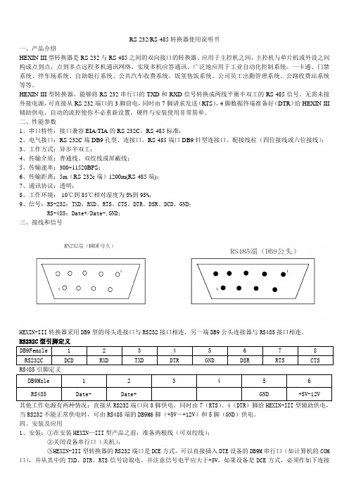
二、性能参数1、串口特性:接口兼容EIA/TIA的RS-232C,RS-485标准;2、电气接口:RS-232C端DB9孔型、连接口,RS-485端口DB9针型连接口、配接线柱(四位接线或六位接线);3、工作方式:异步半双工;4、传输介质:普通线、双绞线或屏蔽线;5、传输速率:300~11520BPS;6、传输距离:5m(RS-232c端)1200m(RS-485端);7、通讯协议:透明;8、工作环境:-10℃到85℃相对湿度为5%到95%;9、信号:RS-232:TXD、RXD、RTS、CTS、DTR、DSR、DCD、GND;RS-485:Date+/Date-,GND;三、接线和信号HEXIN-III转换器采用DB9型的母头连接口与RS232接口相连,另一端DB9公头连接器与RS485接口相连。
RS232C型引脚定义DB9Femsle 1 2 3 4 5 6 7 8RS232C DCD RXD TXD DTR GND DSR RTS CTS RS485引脚定义DB9Msle 1 2 3 4 5 6 RS485 Date- Date+ GND +5V-12V其他工作电源有两种情况:直接从RS232端口向3脚供电,同时由7(RTS)、4(DTR)脚给HEXIN-III型辅助供电,当RS232不能正常供电时,可由RS485端的DB9M6脚(+5V―+12V)和5脚(GND)供电。
RS232-485串口通信详解

串口通信详解一、RS-232RS-232在1962年发布,命名为EIA-232-E,作为工业标准,以保证不同厂家产品之间的兼容。
RS-232-C是美国电子工业协会EIA(Electronic Industry Association)制定的一种串行物理接口标准。
RS是英文“推荐标准”的缩写,232为标识号,C表示修改次数。
RS-232-C总线标准设有25条信号线,包括一个主通道和一个辅助通道。
在多数情况下主要使用主通道,对于一般双工通信,仅需几条信号线就可实现,如一条发送线、一条接收线及一条地线。
RS-232-C标准规定的数据传输速率为每秒50、75、 100、150、300、600、1200、2400、4800、9600、19200波特。
RS-232-C标准规定,驱动器允许有2500pF的电容负载,通信距离将受此电容限制,例如,采用150pF/m的通信电缆时,最大通信距离为15m;若每米电缆的电容量减小,通信距离可以增加。
传输距离短的另一原因是RS-232属单端信号传送,存在共地噪声和不能抑制共模干扰等问题,因此一般用于20m以内的通信。
目前RS-232是PC机与通信工业中应用最广泛的一种串行接口。
RS-232被定义为一种在低速率串行通讯中增加通讯距离的单端标准。
RS-232采取不平衡传输方式,即所谓单端通讯。
收、发端的数据信号是相对于信号地,如从DTE设备发出的数据在使用DB25连接器时是2脚相对7脚(信号地)的电平,DB25各引脚定义参见图1。
典型的RS-232信号在正负电平之间摆动,在发送数据时,发送端驱动器输出正电平在+5~+15V,负电平在-5~-15V 电平。
当无数据传输时,线上为TTL,从开始传送数据到结束,线上电平从TTL电平到RS-232电平再返回TTL电平。
接收器典型的工作电平在+3~+12V与-3~-12V。
由于发送电平与接收电平的差仅为2V至3V左右,所以其共模抑制能力差,再加上双绞线上的分布电容,其传送距离最大为约15米,最高速率为20kb/s。
rs232rs485转换器使用说明书

R S232/RS485转换器使用说明书一、 产品简介HEXIN-III 型转换器之间的双向接口的转换器,应用于主控机之间,主控机与单片机或外设之间构成点到点,点到多点远程多机通信网络,实现多机应答通信通信,广泛地应用于工业自动化控制系统,一卡通、门禁系统、停车系统、自助银行系统、公共汽车收费系统、饭堂售饭系统、公司员工出勤管理系统、公路收费站系统等等。
HEXIN-III 型转器,能够将RS-232串行口的TXD 和RXD 信号转换成两衡半双工的RS-485信号。
无需外接电源,可直接从RS-232端口的3脚窃电,同时由7脚请求发送(RTS ),4脚数据终端准备好(DTR )给HEXIN-III 辅助供电,自动的流控使你不必重新设置,硬件与安装软件使用非常简单。
二、 性能参数1、 串口特性:接口兼容EIA/TIA 的RS-232C ,RS-485标准。
2、 电气接口:RS-232端DB9孔型边接口,RS-485端DB9针型连接器、配接线柱(五位接线)。
3、 工作方式:异步半双工。
4、 传输介质:普通线、双绞线或屏蔽线。
5、 传输速率:300~115-21BDS 。
6、 传输距离:5米(RS-232端)1.200米(RS-485端)。
7、 通信协议:透明。
8、 工作环境:-10℃到85℃相对湿度为5%到95%。
9、 信号:RS-232:TXD 、RXD 、RTS 、CTS 、DTR 、DSR 、DCD 、CND ;RS-485:Date+、Date-。
GND 三、接线和信号:RS232端(DB9母头) RS485(DB9M 公头)HEIN-III 转换器采用DB9型的母头连接口与RS232接口相连,另一端DB9的公头连接器与RS485接口相连。
RS232引脚定义RS485引用脚定义其工作电源有两种情况:直接从RS232端口向3脚供电,同时,由7(RTS )、4(DTR )脚给HEXIIN-III 型辅助供电,当RS232不能正常供电时,可由RS485端的DB9M6(+12V )和5脚(GND )供电。
HC-12用户手册V2.3 (最新版)

邮编:510665 电话:4008881803 销售、技术 QQ:4008881803
HC‐12 无线转串口通信模块用户手册
版本信息
HC-12V2.3
广州汇承信息科技有限公司
发布日期
2014 年 09 月 18 日
修改记录
1. 增加 FU2 模式下发送数据时间间隔的说明。(2013.10.17) 2. 修正应用实例及电路中 HC-12 模块与 MCU 串口连接的线路图。(2013.12.26) 3. FU3 模式 1200 波特率恢复成和 1.13 版本的一样,同时增加 FU4 模式。
广州汇承信息科技有限公司
模式时,超过 4800 bps 的串口波特率一律会被自动降低为 4800 bps。FU2 模式下,只适用
传输少量数据(每个数据包在 20 个字节以内),数据包发送时间间隔不能太短(最好在 2
秒以上),否则会造成数据丢失。
FU4 模式为超远距离通信模式,串口波特率固定为 1200bps,空中波特率为 500bps。
⑶ 四种串口透传模式
HC-12 模块出厂时串口透传模式默认为 FU3。此时,模块工作于全速状态下,空闲工
作电流为 16mA 左右。在此模式下,模块会根据串口波特率自动调节无线传输空中波特率,
串口 RS232 485 422 转 WiFi 以太网服务器用户手册说明书

串口 RS232/485 /422 转 WiFi/以太网服务器用户手册串口RS232/485/422 转WiFi/以太网服务器用户手册V1.3FB-W210上海丰宝电子信息科技有限公司版本信息说明版本型号说明版本修改时间修改内容Rev.1 2015 年04 月012 日创建原始文档Rev.2 2016 年09 月20 日增加了Modbus TCP 转换功能Rev.3 2019 年05 月16 日增加虚拟串口透传通道说明所有权信息未经版权所有者同意,不得将本文档的全部或者部分以纸面或者电子文档的形式重新发布。
本文档只用于辅助读者使用产品,上海丰宝电子信息科技有限公司不对使用该文档中的信息而引起的损失或者错误负责。
本文档描述的产品和文本正在不断地开发和完善中。
上海丰宝电子信息科技有限公司有权利在未通知用户的情况下修改本文档。
目录1.产品概述 (5)1.1概述 (5)1.2产品参数 (5)1.3主要应用 (7)2.硬件介绍 (8)2.1接口定义 (9)2.2RS232 接口说明 (10)2.3RS485 接口说明 (11)2.4RS422 接口说明 (11)2.5RJ45 接口说明 (11)2.6机械尺寸 (12)3.功能描述 (12)3.1基础网络协议 (13)3.2无线组网 (13)3.2.1基于AP 的无线网络 (14)3.2.2基于STA 的无线网络 (14)3.2.3AP+STA 方式的无线网络 (15)3.2.4IOT Manager 软件配置 (16)3.2.5网页配置方式 (17)3.3以太网接口功能 (17)3.3.1以太网接口+Wi-Fi 组合功能 (18)3.3.2以太网接口功能(路由模式) (18)3.3.2 以太网接口功能(桥接模式) (19)3.4工作模式 (21)3.4.1透明传输模式 (21)3.4.2TCP Server (21)3.4.3多Socket 通讯 (22)3.4.4HTTP 模式 (22)3.4.5Telnetd 模式 (26)3.4.6Web Socket 模式 (27)3.4.7MQTT 模式 (29)3.4.8阿里IOT 和阿里Studio (30)串口 RS232/485 /422 转 WiFi/以太网服务器用户手册3.4.9AES/DES3/TLS 数据加密 (30)3.5TCP Keepalive (31)3.6超时时间Timeout (32)3.7路由设置 (32)3.8UART 自动成帧功能 (33)3.8.1UART 自由组帧模式 (33)3.8.2UART 自动成帧模式 (34)3.8.3标签功能 (34)3.9Modbus 协议 (35)3.10Cli 命令 (35)3.11串口流控和RS485 功能 (36)3.12固件升级 (36)3.13网页功能 (37)3.14Auto-IP 功能 (37)3.15NTP 功能 (38)3.16注册包功能 (39)3.17心跳功能 (41)3.18IOT Server 工具软件 (41)3.19虚拟通道功能 (42)3.20参数保存功能 (42)4.快速应用 (44)4.1Auto-IP 模式下的TCP/IP 到串口透传测试 (44)4.2基于AP 组网模式下的测试 (50)4.3基于AP+以太网组网 (54)4.4基于STA 无线网络模式组网 (54)4.4.1基于STA 无线网络模式的虚拟串口透传功能 (55)4.4.2基于STA 模式的RS485 Modbus RTU 到Modbus TCP 转换功能 (59)4.5基于AP-STA 无线网络模式组网 (62)4.6基于AP-STA 无线级联模式组网 (63)4.7基于AP-STA 无线桥接模式组网 (63)5.售后服务及技术支持 (89)产品概述1.1.概述FB-W210 串口服务器提供了一种 RS232/RS485/RS422 和 Wi-Fi/Ethernet 之间协议转换的产品,满足工业产品串口到无线或者以太网数据传输的通道的解决方案,本产品集成了 MAC 等以太网硬件协议,集成了 TCP/IP 协议栈、内存管理、10/100M 以太网收发器、高速串口、RS232、RS485、RS422 等丰富的硬件接口,并且基于 eCos 操作系统,产品包含了 web 网页,可以方便的供远程配置、监控和调试。
15路继电器可编程模块485及232产品使用手册设计资料
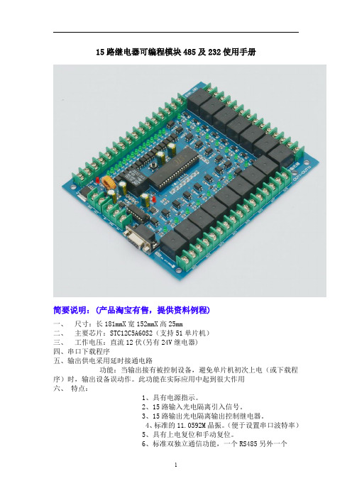
15路继电器可编程模块485及232使用手册简要说明:(产品淘宝有售,提供资料例程)一、尺寸:长181mmX宽152mmX高25mm二、主要芯片:STC12C5A60S2(支持51单片机)三、工作电压:直流12伏(另有24V继电器)四、串口下载程序五、输出供电采用延时接通电路功能:当输出接有被控制设备,避免单片机初次上电(或下载程序)时,输出设备误动作。
此功能在实际应用中起到很大作用六、特点:1、具有电源指示。
2、15路输入光电隔离引入信号。
3、15路输出光电隔离输出控制继电器。
4、标准的11.0592M晶振。
(便于设置串口波特率)5、具有上电复位和手动复位。
6、标准双独立通信功能,一个RS485另外一个RS232。
7、带有掉电存储功能,该单片机内部集成。
8、输入15路具有LED指示。
9、输出15路具有LED指示。
10、15路12V继电器控制,控制设备。
11、可控制交流220V/10A一下设备。
12、具有双通信功能(可以上位机控制)。
13、单片机无加密,可插拔更换,带有程序下载口,可随意更改程序。
使用说明:【标注说明】【接线图】【应用举例】【可以作为输入设备的产品】【可作为输出控制的设备】【原理图】由于原理图比较大,购买后提供PDF格式的。
【PCB图】【上位机控制界面】【测试程序】实现功能:STC12C5A60S2单片机之测试程序使用芯片:STC12C5A60S2晶振:11.0592MHZ波特率:115200编译环境:Keil作者:zhangxinchun淘宝店:汇诚科技【声明】此程序仅用于学习与参考,引用请注明版权和作者信息!*********************************************************************/#include"STC12C5A60S2.H"#include"INTRINS.H"#define uchar unsigned char//宏定义无符号字符型#define uint unsigned int//宏定义无符号整型bit write=0;//写的标志;uchar dat=0xee;//用于存储单片机接收发送缓冲寄存器SBUF里面的内容uchar sj1;//存储数据值uchar sj2;//存储数据值uchar sj3;//存储数据值/*sfr IAP_DATA=0xC2;sfr IAP_ADDRH=0xC3;sfr IAP_ADDRL=0xC4;sfr IAP_CMD=0xC5;sfr IAP_TRIG=0xC6;sfr IAP_CONTR=0xC7;sfr P4=0xC0;*///定义Flash操作等待时间及允许IAP/ISP/EEPROM操作的常数//#define ENABLE_ISP0x80//系统工作时钟<30MHz时,对IAP_CONTR寄存器设置此值//#define ENABLE_ISP0x81//系统工作时钟<24MHz时,对IAP_CONTR寄存器设置此值#define ENABLE_ISP0x82//系统工作时钟<20MHz时,对IAP_CONTR寄存器设置此值//#define ENABLE_ISP0x83//系统工作时钟<12MHz时,对IAP_CONTR寄存器设置此值//#define ENABLE_ISP0x84//系统工作时钟<6MHz时,对IAP_CONTR寄存器设置此值//#define ENABLE_ISP0x85//系统工作时钟<3MHz时,对IAP_CONTR寄存器设置此值//#define ENABLE_ISP0x86//系统工作时钟<2MHz时,对IAP_CONTR寄存器设置此值//#define ENABLE_ISP0x87//系统工作时钟<1MHz时,对IAP_CONTR寄存器设置此值初始定义*********************************************************************//*定义输入口*/sbit IN1=P1^0;sbit IN2=P1^1;sbit IN3=P1^4;sbit IN4=P1^5;sbit IN5=P1^6;sbit IN6=P1^7;sbit IN7=P3^2;sbit IN8=P3^3;sbit IN9=P3^4;sbit IN10=P3^5;sbit IN11=P3^6;sbit IN12=P3^7;sbit IN13=P2^2;sbit IN14=P2^1;sbit IN15=P2^0;/*定义输出口*/sbit OUT1=P2^3;sbit OUT2=P2^4;sbit OUT3=P2^5;sbit OUT4=P2^6;sbit OUT5=P2^7;sbit OUT6=P4^4;sbit OUT7=P4^5;sbit OUT8=P0^7;sbit OUT9=P0^6;sbit OUT10=P0^5;sbit OUT11=P0^4;sbit OUT12=P0^3;sbit OUT13=P0^2;sbit OUT14=P0^1;sbit OUT15=P0^0;/********************************************************************函数声明*********************************************************************/ union union_temp16{uint un_temp16;uchar un_temp8[2];}my_unTemp16;uchar Byte_Read(uint add);//读一字节,调用前需打开IAP功能void Byte_Program(uint add,uchar ch);//字节编程,调用前需打开IAP功能void Sector_Erase(uint add);//擦除扇区void IAP_Disable();//关闭IAP功能void Delay();/********************************************************************延时函数*********************************************************************/ void delay(uchar t){uchar i,j;for(i=0;i<t;i++){for(j=13;j>0;j--);{;}}}/********************************************************************功能:串口初始化,波特率9600,方式1*********************************************************************/ void Init_Com(void){TMOD=0x20;PCON=0x00;SCON=0x50;TH1=0xFd;TL1=0xFd;TR1=1;}/********************************************************************全开函数*********************************************************************/ void quankai(){uchar k;k=10;OUT1=0;delay(k);OUT2=0;delay(k);OUT3=0;delay(k);OUT4=0;delay(k);OUT5=0;delay(k);OUT6=0;delay(k);OUT7=0;delay(k);OUT8=0;delay(k);OUT9=0;delay(k);OUT10=0;delay(k);OUT11=0;delay(k);OUT12=0;delay(k);OUT13=0;delay(k);OUT14=0;delay(k);OUT15=0;delay(k);}/********************************************************************全关函数*********************************************************************/ void quanguan(){uchar k;k=10;OUT1=1;delay(k);OUT2=1;delay(k);OUT3=1;delay(k);OUT4=1;delay(k);OUT5=1;delay(k);OUT6=1;delay(k);OUT7=1;delay(k);OUT8=1;delay(k);OUT9=1;delay(k);OUT10=1;delay(k);OUT11=1;delay(k);OUT12=1;delay(k);OUT13=1;delay(k);OUT14=1;delay(k);OUT15=1;delay(k);}/********************************************************************接收数据判断函数*********************************************************************/ chuankou(){switch(dat)//接收数据判断{uchar k;k=10;case'I':quankai();SBUF=dat;dat=0xee;write=1;break;//全开case'i':quanguan();SBUF=dat;dat=0xee;write=1;break;//全关case'A':OUT1=0;delay(k);SBUF=dat;dat=0xee;write=1;break;//第一路开case'B':OUT2=0;delay(k);SBUF=dat;dat=0xee;write=1;break;//第二路开case'C':OUT3=0;delay(k);SBUF=dat;dat=0xee;write=1;break;//第三路开case'D':OUT4=0;delay(k);SBUF=dat;dat=0xee;write=1;break;//第四路开case'E':OUT5=0;delay(k);SBUF=dat;dat=0xee;write=1;break;//第五路开case'F':OUT6=0;delay(k);SBUF=dat;dat=0xee;write=1;break;//第六路开case'G':OUT7=0;delay(k);SBUF=dat;dat=0xee;write=1;break;//第七路开case'H':OUT8=0;delay(k);SBUF=dat;dat=0xee;write=1;break;//第八路开case'J':OUT9=0;delay(k);SBUF=dat;dat=0xee;write=1;break;//第九路开case'K':OUT10=0;delay(k);SBUF=dat;dat=0xee;write=1;break;//第十路开case'L':OUT11=0;delay(k);SBUF=dat;dat=0xee;write=1;break;//第十一路开case'M':OUT12=0;delay(k);SBUF=dat;dat=0xee;write=1;break;//第十二路开case'N':OUT13=0;delay(k);SBUF=dat;dat=0xee;write=1;break;//第十三路开case'O':OUT14=0;delay(k);SBUF=dat;dat=0xee;write=1;break;//第十四路开case'P':OUT15=0;delay(k);SBUF=dat;dat=0xee;write=1;break;//第十五路开case'a':OUT1=1;delay(k);SBUF=dat;dat=0xee;write=1;break;//第一路关case'b':OUT2=1;delay(k);SBUF=dat;dat=0xee;write=1;break;//第二路关case'c':OUT3=1;delay(k);SBUF=dat;dat=0xee;write=1;break;//第三路关case'd':OUT4=1;delay(k);SBUF=dat;dat=0xee;write=1;break;//第四路关case'e':OUT5=1;delay(k);SBUF=dat;dat=0xee;write=1;break;//第五路关case'f':OUT6=1;delay(k);SBUF=dat;dat=0xee;write=1;break;//第六路关case'g':OUT7=1;delay(k);SBUF=dat;dat=0xee;write=1;break;//第七路关case'h':OUT8=1;delay(k);SBUF=dat;dat=0xee;write=1;break;//第八路关case'j':OUT9=1;delay(k);SBUF=dat;dat=0xee;write=1;break;//...case'k':OUT10=1;delay(k);SBUF=dat;dat=0xee;write=1;break;//...case'l':OUT11=1;delay(k);SBUF=dat;dat=0xee;write=1;break;//...case'm':OUT12=1;delay(k);SBUF=dat;dat=0xee;write=1;break;//...case'n':OUT13=1;delay(k);SBUF=dat;dat=0xee;write=1;break;//...case'o':OUT14=1;delay(k);SBUF=dat;dat=0xee;write=1;break;//...case'p':OUT15=1;delay(k);SBUF=dat;dat=0xee;write=1;break;//...default:break;//跳出}}/********************************************************************按键函数*********************************************************************/KEY(){uchar k;k=200;if(IN1==0){delay(k);if(IN1==0){delay(k);OUT1=!OUT1;while(!IN1);delay(k);write=1; }}if(IN2==0){delay(k);if(IN2==0){delay(k);OUT2=!OUT2;while(!IN2);delay(k);write=1; }}if(IN3==0){delay(k);if(IN3==0){delay(k);OUT3=!OUT3;while(!IN3);delay(k);write=1; }}if(IN4==0){delay(k);if(IN4==0){delay(k);OUT4=!OUT4;while(!IN4);delay(k);write=1; }}if(IN5==0){delay(k);if(IN5==0){delay(k);OUT5=!OUT5;while(!IN5);delay(k);write=1; }}if(IN6==0){delay(k);if(IN6==0){delay(k);OUT6=!OUT6;while(!IN6);delay(k);write=1; }}if(IN7==0){delay(k);if(IN7==0){delay(k);OUT7=!OUT7;while(!IN7);delay(k);write=1; }}if(IN8==0){delay(k);if(IN8==0){delay(k);OUT8=!OUT8;while(!IN8);delay(k);write=1; }}if(IN9==0){delay(k);if(IN9==0){delay(k);OUT9=!OUT9;while(!IN9);delay(k);write=1; }}if(IN10==0){delay(k);if(IN10==0){delay(k);OUT10=!OUT10;while(!IN10);delay(k);wr ite=1;}}if(IN11==0){delay(k);if(IN11==0){delay(k);OUT11=!OUT11;while(!IN11);delay(k);wr ite=1;}}if(IN12==0){delay(k);if(IN12==0){delay(k);OUT12=!OUT12;while(!IN12);delay(k);wr ite=1;}}if(IN13==0){delay(k);if(IN13==0){delay(k);OUT13=!OUT13;while(!IN13);delay(k);wr ite=1;}}if(IN14==0){delay(k);if(IN14==0){delay(k);OUT14=!OUT14;while(!IN14);delay(k);wr ite=1;}}if(IN15==0){delay(k);if(IN15==0){delay(k);OUT15=!OUT15;while(!IN15);delay(k);wr ite=1;}}}/********************************************************************主函数*********************************************************************/ void main(void){uint eeprom_address;P4SW|=0x20;//配置P4.5为IO口P4M0|=0x10;//配置P4.4为IO口P4M1|=0x10;Init_Com();//串口初始化eeprom_address=0x01;//将测试起始地址送eeprom_addresssj1=Byte_Read(1);//读EEPROM的值,存到read_eepromsj2=Byte_Read(2);//读EEPROM的值,存到read_eepromsj3=Byte_Read(3);//读EEPROM的值,存到read_eepromP0=sj1;P2=sj2;P4=sj3;while(1){chuankou();//接收数据判断函数if(RI)//扫描判断是否接收到数据,{dat=SBUF;//接收数据SBUF赋与datRI=0;//RI清零。
- 1、下载文档前请自行甄别文档内容的完整性,平台不提供额外的编辑、内容补充、找答案等附加服务。
- 2、"仅部分预览"的文档,不可在线预览部分如存在完整性等问题,可反馈申请退款(可完整预览的文档不适用该条件!)。
- 3、如文档侵犯您的权益,请联系客服反馈,我们会尽快为您处理(人工客服工作时间:9:00-18:30)。
(HC-12-RS232/RS485)串口继电器模块使用说明书
产品特点
●DC12V1A供电
●控制驱动带有光电隔离,安全稳定
●通讯方式支持RS232\RS485
●自定义通信协议(可根据客户需要定制)
●采用导轨式安装方式
产品功能
●支持16个地址设置
●波特率9600 8 1
●支持单开、单关、全开、全关、部分开、部分关
主要参数
●触点容量10A/30VDC 10A/250VAC
●耐久性10万次
●数据接口RS232/RS485
●额定电压DC 9-12V
●电源指示1路红色LED灯指示
●通讯指示无
●输出指示LED灯指示
●温度范围工业级-40~85度
●通讯格式9600 N 8 1
●软件支持配套软件串口助手
接口简介如下:
●1、2、3对应继电器常闭、公共点、常开
●RS232接口采用DB9母头。
使用USB转串口线需要使用公头,使用串口线为直通串口
线
●RS485接口为5.08间距的接线端子,从左至右为A B GND VCC5V
●电源为DC12V1A 指示灯为红色LED
控制电路接线图如下:
上位机软件界面:
●串口号可以在电脑的设备管理器里查看
●模块出厂地址为00
通信协议:
模块默认地址00 波特率9600 8 1 十六进制
AA5A000100FF 打开继电器1 AA5A000000FF 关闭继电器1
AA5A001100FF 打开继电器2 AA5A001000FF 关闭继电器2
AA5A002100FF 打开继电器3 AA5A002000FF 关闭继电器3
AA5A003100FF 打开继电器4 AA5A003000FF 关闭继电器4
AA5A004100FF 打开继电器5 AA5A004000FF 关闭继电器5
AA5A005100FF 打开继电器6 AA5A005000FF 关闭继电器6
AA5A006100FF 打开继电器7 AA5A006000FF 关闭继电器7
AA5A007100FF 打开继电器8 AA5A007000FF 关闭继电器8
AA5A008100FF 打开继电器9 AA5A008000FF 关闭继电器9
AA5A009100FF 打开继电器10 AA5A009000FF 关闭继电器10
AA5A00A100FF 打开继电器11 AA5A00A000FF 关闭继电器11
AA5A00B100FF 打开继电器12 AA5A00B000FF 关闭继电器12
AA5A00C100FF 打开继电器13 AA5A00C000FF 关闭继电器13
AA5A00D100FF 打开继电器14 AA5A00D000FF 关闭继电器14
AA5A00E100FF 打开继电器15 AA5A00E000FF 关闭继电器15
AA5A00F100FF 打开继电器16 AA5A00F000FF 关闭继电器16
AA5A00FF00FF 打开所有继电器AA5A00FE00FF 关闭所有继电器
AA5A00FC00FF 查询继电器状态返回 AA5A00FC00FF (FC后面的两个十六进制对应的两组8位二进制为十六个继电器的状态 1为打开,0为关闭)
AA5A00FD00FF 打开部分继电器
以下是对打开部分继电器的详解:
FD后面的一个十六进制为打开的指令
比如当发送的是AA5A00FD99FF的时候打开的是第1,4,5,8继电器。
99转换成二进制是10011001 其中1为打开 0为关闭。
第一位1对应的是1号继电器。
具体为把一个十六进制作为八个二进制用,对应八个继电器。
这种方式可以同时打开1到8个继电器。
常见问题解答:
1、需要控制的路数多于选择的串口继电器控制模块怎么办?
答:这种情况就要采用RS485通信了。
使用多个模块扩展使用,最多可以控制255路。
2、最大控制电流多少A?
答:10A
3、RS232通信距离多少米?RS485通信距离多少米?
答:RS232通信距离理论15米(传输变慢)。
RS485通信距离理论1200米(具体和通信线的材质有关)
4、供电可以使用DC24V吗?
答:4路和16路可以支持DC24V供电,需要给店家说明。
5、上位机界面可以修改吗?
答:可以修改。
提供C#和python两种语言的上位机程序和源代码。
也可以按照客户要求修改,需要收取一定的费用。
常见无法控制情况解答:
1、检查拨码开关是否在正确的位置,它采用8421编码,出厂是0,上位机软件需要设置为0进行控制。
2、检查通信方式。
一些客户拍的是RS485通信的方式,使用的时候采用RS232控制,这种情况需要修改电路板上P1,P2的连接点。
3、如果买家自己选用的串口线,需要使用直连线,一公一母的接头。