西安西普XHF100变频器说明书使用手册(20210217105305)
西安西普软启动说明书2

5.基本接线及外接端子图5-1给出了STR 电动机软起动器的全部外接线接口,具体说明见表5-1外接端子说明。
STR 软起动器的基本接线图图 5-1★ 软起动器的起动、停止也可采用二线控制,利用RU N 和CO M 的闭合和断开作为动、停止信号。
起STR 软起动器的外接端子说明表5-1★表示外控有两种接线方式,详见基本接线图5-1。
STR系列A型软起动器(7.5KW-75KW)K22和 K24 厂家已占用,用户不能使用.上述图5-1及表5-1给出了STR电动机软起动器所有的外接端子及说明,在接线时,注意以下事项:主电路接线— STRA型产品主电路有6个接线端子,即R.S.T(接进线电源) U.V.W(接电动机),详请参见图6-1。
—STRB型产品主电路有9个接线端子,除上述6个相同外,还有 3个接旁路接触器专用接线端子 U1.V1.W1,其接线参见图6-2。
控制电路STR 软起动器共有16位外部控制端子,为用户实现外部信号控制、远程控制及系统控制提供方便,这16位端子安装在软起动器的主控板上。
在软起动内部有端子引出,可直接接线。
在使用过程中,如用户采用本机键盘操作,而不需远控或外部信号控制,则相应的端子不用接线,其接线排列顺序如下图5-2。
R U NJ O G起动点动停机公共端复位起动完成输出故障输出旁路控制12345678910111213141516图5-2—— 其中RUN (起动端子)、STOP (停止端子)、JOG (点动端子)在使用时应进行相应的参数设置,详见表9-1“参数设置及修改”中第11项。
其接线请参见图6-1、图6-2、图6-3。
—— OC (起动完成输出)、I0(4~20mA )输出为有源输出。
—— K14、K11、K12(故障输出)及K24、K21、K22(旁路输出)均为无源输出端子,其接线请参见图6-2、图6-3。
6.STR 软起动器典型应用接线图STR 系列A型软起动装置典型应用接线图图6-1STR 系列B 型软起动器典型应用接线图L1L2L3Q FNK 21K 22K 14K 11K 1212VO C C O MK 24K MR U N S TO P C O M JO GB 型旁路控制故障输出起动完成输出R STUVW U 1V 1W 1三线控制二线控制R U N S TO P COMKK M注:用户可根据自己的要求配置旁路接触器K M , 容量可根据电机的额定电流来选型。
西安西普XHF100变频器变频器面板信息解读

西普XHF100A系列矢量通用变频器面板信息解读1、西普XHF100A系列矢量通用变频器是我们120万吨运行班组使用率非常高的主要生产类电气设备之一2.手操器面板功能键含义及显示区常用内容解读2.1、操作面板图2.2、按键功能说明2.2.1、PRG/ESC(编程键),一级菜单进入或退出键2.2.2、DATA/ENT(确定键),逐级进入菜单画面,设定参数确认2.2.3、(递增键),数据或功能码的递增2.2.4、(递减键),数据或功能码的递减2.2.5、》/SHIFT右移位键,在停机显示界面和运行显示界面下,可右移循环显示参数;在修改参数时,可以选择参数的修改位2.2.6、RUN(运行键),在键盘操作方式下,用于运行操作2.2.7、STOP/RST(停止复位键),运行状态时,按此键可用于停止运行操作:该功能码P7.04制约,故障报警状态时,所有控制模式都可以用该键来复位操作。
2.2.8、QUICK/JOG(快捷多功能键),该功能由功能码P7.03确定2.2.8.1、0:移位键切换显示状态2.2.8.2、寸动运行2.2.8.3、正转反转切换,为正反转切换键2.2.8.4、清除UP/DOWN设定,清除由UP/DOWN设定的频率值2.2.8.5、快速调式模式(按非出厂值参数调试)2.2.9、RUN+STOP(组合键),RUN键和STOP/RST同时被按下,变频器自由停机2.3、功能指示灯说明2.3.1、功能指示灯说明2.3.1.1、RUN/TUNE,运行状态指示灯,灯灭时表示变频器处于停机状态,灯闪烁表示变频器处于参数处学习状态,灯亮时表示变频器处于运行状态2.3.1.2、FWD/REV,正反转指示灯,灯灭表示处于正转状态,灯亮表示处于反转状态2.3.1.3、LOCAL/REMOT,控制模式指示灯,灯灭表示键盘控制状态,灯闪烁表示端子控制状态,灯亮表示远程通讯控制状态2.3.1.4、TRIP,过载预报警指示灯,灯灭表示变频器正常状态,灯闪烁表示变频器过载预报警状态,灯亮表示变频器故障状态。
克罗韦尔 PowerFlex 527 交流变频器 说明书

PowerFlex 527 交流变频器目录号25C用户手册中文版说明书用户重要须知固态设备具有与机电设备不同的运行特性。
Safety Guidelines for the Application, Installation and Maintenance of Solid State Controls (固态控制设备的应用、安装与维护安全指南,出版号:SGI-1.1,可向您当地的罗克韦尔自动化销售处索取或通过 /literature/ 在线索取) 描述了固态设备和硬接线机电设备之间的一些重要差异。
由于存在这些差异,同时固态设备的应用又非常广泛,因此,负责应用此设备的所有人员都必须确保仅以可接受的方式应用此设备。
任何情况下,对于因使用或操作本设备造成的任何间接或连带损失,罗克韦尔自动化有限公司概不负责。
本手册中包含的示例和图表仅用于说明。
由于任何具体的安装都存在众多差异和要求,罗克韦尔自动化有限公司对于依据这些示例和图表所进行的实际应用不承担任何责任和义务。
对于因使用本手册中所述信息、电路、设备或软件而引起的专利问题,罗克韦尔自动化有限公司不承担任何责任。
未经罗克韦尔自动化有限公司的书面许可,不得复制本手册的全部或部分内容。
在整本手册中,我们在必要的地方使用了以下注释,来提醒您注意相关的安全事宜。
Allen-Bradley 、Rockwell Software 、Rockwell Automation 、PowerFlex 、Connected Components Workbench 、Studio 5000、Studio 5000 Logix Designer 和 T echConnect 罗克韦尔自动化有限公司的商标。
不属于罗克韦尔自动化的商标是其各自所属公司的财产。
警告:标识在危险环境下可能导致爆炸,进而导致人员伤亡、物品损坏或经济损失的操作或情况。
注意:标识可能导致人员伤亡、物品损坏或经济损失的操作或情况。
烁普变频器使用说明书

1.1安全注意事项
●绝不可将交流电源接至变频器输出端U、V、W等端子。
●在接通电源后,不可实施配线,检查等作业。
●关闭电源,在键盘显示熄灭后5分钟之内,请勿触摸机内电路板及任何零部件,且必须用仪表确认机内电容已放电完毕,方可实施机内作业,否则有触电的危险。
●人体静电会严重损坏内部MOS场效应电晶体等,未采取防静电措施时,请勿用手触摸印刷电路板及IGBT等内部器件,否则可能引起故障。
(7)禁止使用在易燃性、可燃性、爆炸性气体、液体或固体的危险环境。
2.2安装方向与空间
变频调速器要安装于室内通风良好的场所,并采用壁挂式或立柜式。并与周围相邻物品或挡板(墙)必须保持足够的空间。如下图所示:
2.3配线
变频调速器配线,分为主回路及控制回路两部分。用户必须依照下图所示的配线回路正确连接。
※ 为尽量减少电磁干扰的影响,当使用的电磁接触器及继电器等距离变频器较近时,应考虑加装浪涌吸收装置。
※ 变频器的外部控制线需加隔离装置或采用屏蔽线。
※ 输入指令信号连线除屏蔽外还应单独走线,最好远离主回路接线。
※ 载波频率小于3KHz时,变频器与电机间最大距离应在50米以内,载波频率大于4KHz时,应适当减少此距离,此接线最好敷设于金属管内。
例:P009一段加速时间出厂值10.0sec修改为15.0sec
第四章功能参数一览表
基本参数
序号
功能描述
设定值范围及定义
出厂值
运行时可修改
参见页
P001
运行控制方式
0:操作键盘
1:端子台
2:RS485控制
0
×
17
P002
频率设定模式
0:操作键盘上下键
ABB-ACS100变频器使用手册

Comp-AC用户手册ACS100变频器0.12 to 2.2 kWACS 100 变频器用户手册英文:3BFE 64307622 R0125中文:3ABD00008839 版本:C生效: 2002年11月20日© 2000 ABB Industry Oy安全注意事项警告!只有专业技术人员允许安装ACS100。
警告!主回路电源得电后即存在危险电压。
电源断开后,等待5分钟再打开前面板。
检查前请测量直流端子 (Uc+, Uc-) 电压。
参看G。
警告!电机停止后,在主回路端子上 (U1, V1, W1 和 U2, V2, W2 及U c+, U c-)依然有危险电压存在。
警告! ACS400 断电后,在继电器端子上 ( RO1, RO2, RO3)依然可能有外部危险电压。
警告! ACS100不是可以在现场修补的单元,因此不要试图修理损坏的单元,请与供应商联系,重新更换新单元。
警告!当输入电源断电之后再次恢复时,如果外部运行指令为ON,ACS100 将自动起动。
警告!当两个以上的ACS100/140/400 的控制端子并联使用时,用于控制连接的辅助电源应来自同一个单元或外部电源。
警告!参数的变更或设备设置的更改将影响ACS100的功能和操作,请确定您所作的改变不会涉及人身和财产的安全。
警告!散热器的温度可能很高(参看S)。
注意!欲获取详细的技术信息,请与供应商联系。
iii目录安全注意事项 (i)安装 (1)安装参考 (2)环境限制 (2)外形尺寸 (mm) (2)安装 ACS100 (3)打开塑料外壳 (6)粘贴警告标牌 (6)电缆连接 (6)端子与接口 (7)铭牌标识 (8)浮地电网 (8)电机 (8)控制端子 (9)配置开关 (10)连接示例 (11)复原外壳 (11)通电 (12)保护特性 (12)电机过载保护 (13)ACS100负载能力 (13)型号和技术数据 (14)产品规范 (17)环保要求 (17)附件 (18)编程 (19)控制盘 (19)控制模式 (19)输出显示 (20)菜单结构 (20)设定参数值 (20)菜单功能 (21)故障诊断显示 (21)故障复位 (22)ACS100 参数表 (23)Group 01: 实际值和状态参数 (25)Group 02: 电机参数和限制值 (25)Group 03: 传动控制 (26)Group 04: 输入/输出 (27)Group 05: 监控器 (28)iii故障诊断 (31)概述 (31)报警和故障显示 (31)故障复位 (31)ACS100 EMC 指导书 (35)ACS100 售后服务说明 (42)iv1安装使用前请仔细阅读安装说明。
西驰变频器与西门子PLC通信方法.pdf

-3-
R
西安西驰电气有限责任公司 CFC4000 系列变频器使用说明书 4.2 DRIVE 模式和 PRGM 模式下的显示内容………………………………………28 4.3 参数群说明……………………………………………………………………29 4.4 键盘操作运行…………………………………………………………………29 第 5 章 变频器参数设定及说明……………………………………………………………32 5.1 频率指令 F-□□……………………………………………………………… 32 5.2 运行中可变更的参数 R-□□…………………………………………………33 5.3 控制参数 C-□□……………………………………………………………… 41 5.4 系统参数 S-□□……………………………………………………………… 56 5.5 监控参数 E-□□……………………………………………………………… 89 第 6 章 异常诊断 …………………………………………………………………………93 6.1 概述………………………………………………………………………… 93 6.2 故障原因及处理对策……………………………………………………… 93 第 7 章 选件 …………………………………………………………………………… 97 7.1 外围设备和任意选件连接图………………………………………………97 7.2 外围设备的功能说明……………………………………………………… 97
1.2 安全注意事项
● 安装前
危险
1.损伤的变频器及缺少部件的变频器请不要使用;有受伤危险;
西安西普软启动器说明书

西安西普软启动器说明书----------专业最好文档,专业为你服务,急你所急,供你所需-------------文档下载最佳的地方----------专业最好文档,专业为你服务,急你所急,供你所需-------------文档下载最佳的地方----------专业最好文档,专业为你服务,急你所急,供你所需-------------文档下载最佳的地方----------专业最好文档,专业为你服务,急你所急,供你所需-------------文档下载最佳的地方----------专业最好文档,专业为你服务,急你所急,供你所需-------------文档下载最佳的地方----------专业最好文档,专业为你服务,急你所急,供你所需-------------文档下载最佳的地方----------专业最好文档,专业为你服务,急你所急,供你所需-------------文档下载最佳的地方----------专业最好文档,专业为你服务,急你所急,供你所需-------------文档下载最佳的地方----------专业最好文档,专业为你服务,急你所急,供你所需-------------文档下载最佳的地方----------专业最好文档,专业为你服务,急你所急,供你所需-------------文档下载最佳的地方----------专业最好文档,专业为你服务,急你所急,供你所需-------------文档下载最佳的地方----------专业最好文档,专业为你服务,急你所急,供你所需-------------文档下载最佳的地方----------专业最好文档,专业为你服务,急你所急,供你所需-------------文档下载最佳的地方----------专业最好文档,专业为你服务,急你所急,供你所需-------------文档下载最佳的地方----------专业最好文档,专业为你服务,急你所急,供你所需-------------文档下载最佳的地方----------专业最好文档,专业为你服务,急你所急,供你所需-------------文档下载最佳的地方----------专业最好文档,专业为你服务,急你所急,供你所需-------------文档下载最佳的地方----------专业最好文档,专业为你服务,急你所急,供你所需-------------文档下载最佳的地方----------专业最好文档,专业为你服务,急你所急,供你所需-------------文档下载最佳的地方----------专业最好文档,专业为你服务,急你所急,供你所需-------------文档下载最佳的地方----------专业最好文档,专业为你服务,急你所急,供你所需-------------文档下载最佳的地方----------专业最好文档,专业为你服务,急你所急,供你所需-------------文档下载最佳的地方----------专业最好文档,专业为你服务,急你所急,供你所需-------------文档下载最佳的地方----------专业最好文档,专业为你服务,急你所急,供你所需-------------文档下载最佳的地方----------专业最好文档,专业为你服务,急你所急,供你所需-------------文档下载最佳的地方----------专业最好文档,专业为你服务,急你所急,供你所需-------------文档下载最佳的地方----------专业最好文档,专业为你服务,急你所急,供你所需-------------文档下载最佳的地方----------专业最好文档,专业为你服务,急你所急,供你所需-------------文档下载最佳的地方----------专业最好文档,专业为你服务,急你所急,供你所需-------------文档下载最佳的地方----------专业最好文档,专业为你服务,急你所急,供你所需-------------文档下载最佳的地方----------专业最好文档,专业为你服务,急你所急,供你所需-------------文档下载最佳的地方----------专业最好文档,专业为你服务,急你所急,供你所需-------------文档下载最佳的地方----------专业最好文档,专业为你服务,急你所急,供你所需-------------文档下载最佳的地方----------专业最好文档,专业为你服务,急你所急,供你所需-------------文档下载最佳的地方----------专业最好文档,专业为你服务,急你所急,供你所需-------------文档下载最佳的地方----------专业最好文档,专业为你服务,急你所急,供你所需-------------文档下载最佳的地方----------专业最好文档,专业为你服务,急你所急,供你所需-------------文档下载最佳的地方----------专业最好文档,专业为你服务,急你所急,供你所需-------------文档下载最佳的地方----------专业最好文档,专业为你服务,急你所急,供你所需-------------文档下载最佳的地方----------专业最好文档,专业为你服务,急你所急,供你所需-------------文档下载最佳的地方----------专业最好文档,专业为你服务,急你所急,供你所需-------------文档下载最佳的地方----------专业最好文档,专业为你服务,急你所急,供你所需-------------文档下载最佳的地方----------专业最好文档,专业为你服务,急你所急,供你所需-------------文档下载最佳的地方----------专业最好文档,专业为你服务,急你所急,供你所需-------------文档下载最佳的地方----------专业最好文档,专业为你服务,急你所急,供你所需-------------文档下载最佳的地方----------专业最好文档,专业为你服务,急你所急,供你所需-------------文档下载最佳的地方----------专业最好文档,专业为你服务,急你所急,供你所需-------------文档下载最佳的地方----------专业最好文档,专业为你服务,急你所急,供你所需-------------文档下载最佳的地方----------专业最好文档,专业为你服务,急你所急,供你所需-------------文档下载最佳的地方----------专业最好文档,专业为你服务,急你所急,供你所需-------------文档下载最佳的地方----------专业最好文档,专业为你服务,急你所急,供你所需-------------文档下载最佳的地方----------专业最好文档,专业为你服务,急你所急,供你所需-------------文档下载最佳的地方----------专业最好文档,专业为你服务,急你所急,供你所需-------------文档下载最佳的地方----------专业最好文档,专业为你服务,急你所急,供你所需-------------文档下载最佳的地方----------专业最好文档,专业为你服务,急你所急,供你所需-------------文档下载最佳的地方----------专业最好文档,专业为你服务,急你所急,供你所需-------------文档下载最佳的地方----------专业最好文档,专业为你服务,急你所急,供你所需-------------文档下载最佳的地方----------专业最好文档,专业为你服务,急你所急,供你所需-------------文档下载最佳的地方----------专业最好文档,专业为你服务,急你所急,供你所需-------------文档下载最佳的地方----------专业最好文档,专业为你服务,急你所急,供你所需-------------文档下载最佳的地方----------专业最好文档,专业为你服务,急你所急,供你所需-------------文档下载最佳的地方----------专业最好文档,专业为你服务,急你所急,供你所需-------------文档下载最佳的地方----------专业最好文档,专业为你服务,急你所急,供你所需-------------文档下载最佳的地方----------专业最好文档,专业为你服务,急你所急,供你所需-------------文档下载最佳的地方----------专业最好文档,专业为你服务,急你所急,供你所需-------------文档下载最佳的地方----------专业最好文档,专业为你服务,急你所急,供你所需-------------文档下载最佳的地方----------专业最好文档,专业为你服务,急你所急,供你所需-------------文档下载最佳的地方----------专业最好文档,专业为你服务,急你所急,供你所需-------------文档下载最佳的地方。
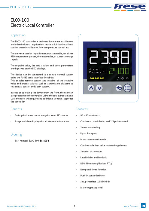
Frese ELCO 100 PID 控制器说明书

Electric Local ControllerFeatures• 96 × 96 mm format• Continuous modulating and 2/3 point control •Sensor monitoring • Up to 5 outputs • Manual/automatic mode• Configurable limit value monitoring (alarms)• Setpoint changeover • Level inhibit and key lock • RS485 interface (Modbus RTU)• Ramp and timer function • Push-in controller insert • Setup interface (USB Mini-B)•Marine type approvalApplicationThe ELCO-100 controller is designed for marine installations and other industrial applications - such as lubricating oil and cooling water installations, flow temperature control etc.The universal analog input is user programmable, for either RTD temperature probes, thermocouples, or current/voltage signals.The setpoint value, the actual value, and other parameters are displayed on the LED displays.The device can be connected to a central control system using the RS485 serial interface (Modbus).This enables remote control and reading of the setpoint value and process value as well as transmission of alarms to to a central control and alarm system.Instead of operating the device from the front, the user can also programme the controller using the setup program and USB interface; this requires no additional voltage supply for the controller.Benefits• Self-optimisation (autotuning) for exact PID control •Large and clear display with all relevant informationOrdering•Part number ELCO-100: 58-8958Electric Local ControllerFunctional descriptionSelf-optimisation (autotuning)Standard features include the tried and tested self-optimization (oscillation method), which makes it possible for the controller to be matched to the control loop by a user who is not a control technology expert.Here,the reaction of the control path to the specific variable changes is evaluated and the controller parameters proportional band, reset time, derivative time, cycle time, and filter time constant are calculated.Ramp functionThe ramp function is used for a constant change of setpointvalue w up to the ramp limit value SP (entered setpointvalue).A rising or a falling edge arises depending on the actualvalue at the time of ramp start t0.The slope is defined by a gradient which is entered duringthe controller configuration.Limit value monitoringThe controller is equipped with two limit value monitoring functions, each with eight configurable alarm functions. Any analog signals can be selected as actual and setpoint value froma selector. When a limit value is exceeded, a signal can be displayed or an internal controller function initiated. With the limit value monitoring, extensive alarm and limit value functions can be implemented.TimerThe timer is started manually or automatically (after power on, for example). When the timer expires, the timer output signal changes its state (configurable). The timer can be used to implement functions like time-limited control or setpoint changeover.Setup programThe setup program provides the user with an easy and comfortable way to configure the controller using a PC.The PC has to be connected to the controllers USB interface (Mini-B type) with a USB cable.Thereby the controller is powered over the USB interface. As a result, no mains supply is required during the configuration.Electric Local ControllerTechnical data ∙ ELCO-100 ControllerPower consumption: Max. 6.6 WVoltage Supply:AC 110 to 240V, +10/-15 %, 48 to 63HzMeasuring accuracy:≤ 0.1 % of measuring rangeAmbient temperature:-10 °C to 55°CStorage temperature:-30°C to 70°CWeight:220 gProtection class:Acc. to DIN EN 60529 , Front IP65/Rear IP20Dimensions:See drawing next pageOperating position:Any positionL,J,U,T,K,E,N,S,R,B,C,D,A1,L,KAnalog Input:ThermocouplePt100/Pt1000/KTYRTDResistance / Potentiometer (0 to 4000Ω)0(2) to 10V (500kΩ input resistance)0(4) to 20mA (< 2.5V burden voltage)Digital Input:Potential-free contactAnalog Output:0(2)(>500Ωload)10Vto0(4) to 20 mA (<450Ω load)Digital Outputs:Relays (N/O contacts) [Max 3A at AC230V or DC30V, resistive load]Logic output 0/14V (Max output current 20mA)RS485 interface:Modbus RTU (Galvanic isolated)controllerController type:Continousmodulating2/3 point controllerDisplay:Two 18-segment LCD display + Pixel matrix LCD for textUpper display: 25mm Color: White / Lower display: 12mm Color: Green Electrical connection:On the back via spring-cage terminalsApproval: c UL us (UL 61010-1 (3. Ed.), CAN/CSA-22.2 No. 61010-1 (3. Ed.))DNV GL (DNVGL-CG-0339)Alarm:Limit value in relation to setpoint valueFixed limit valueElectric Local ControllerDimensionsDisplay and control elements1. 18-segment LCD display (e.g. actual value), 4-digit2. 18-segment LCD display (e.g. setpoint value), parameters,values and text); display ”OK” when exiting editing mode (with change)3. Activity display for ramp function/program, timer, manualmode4. For type ELCO-100: pixel matrix LCD display for displaying menuitems, parameters and values as well as customer-specific text 5. Switching of the digital outputs (yellow = active)6. Up (in the menu: increase value, select previous menu item orparameter; in basic status: increase setpoint value)7. Down (in menu: reduce value, select next menu item orparameter; in basic status: reduce setpoint value)8. Back (in menu: back to previous menu level, exit editing modewithout change; in basic status: configurable function)9. Menu/OK (call up main menu, switch to submenu/level, switchto editing mode, exit editing mode with change)Electric Local ControllerTechnical dataConnection diagramThe connection diagram in this Technote provides preliminary information about the connection possibilities.For the electrical connection use the operating manual delivered with the product.The knowledge and the correct technical execution of the safety information/instructions contained in these documents are mandatory for installation, electrical connection, and startup as well as for safety during operation.The terminal strips on the device rear are equipped with screw terminals. Please refer to the technical data for specifications concerning the conductor cross section.(1)(2)(3)(4)Electric Local ControllerApplication temperature sensorScrew-in RTD temperature probe for marine applications.Temperature Range from -50 to +400 °CThe RTD temperature probes for standard and marine applications is commonly used for measuring temperatures in liquids and gases in pipes and tanks.Application areas:• Ballast water management • Water treatment systems• Generators, motors, and compressors • Heating and air-conditioning industry • For nearly all applications on shipsBenefits• Quick response times – a reduced probe tip allows response times of t0.9 = 14 s to be reached in water • Increased safety – thanks to successful testing by Bureau Veritas•Flexible and time-saving startup – due to availability of different standardized process connections Features• The connection head is suitable for ambient temperatures up to 100 °C.• Normally fitted with a Pt100 temperature sensor according to DIN EN 60751, Class B in 4-wire circuit connections.•The intelligent design of the RTD temperature probe with a fixed measuring insert allows temperatures to be measured under standard conditions.• Versions of class A or AA are also possible.• Versions with a reduced probe tip are available for quicker response times.• A transmitter can be integrated into the terminal head as an option.•The RTD temperature probes are certified according to Bureau Veritas.Electric Local ControllerTechnical data ∙ RTD temperature sensorTerminal head Form B DIN EN 50446, die-cast aluminum, M20 × 1.5Seal IP65Measuring insert Pt100 temperature sensor DIN EN 60751, cl. B, 4-wire circuit, permanently installed Response times t0.5 = 5 s, t0.9 = 14 s in water 0.4 m/s; ø6 mm Transmitter Accessories Programmable transmitter, output 4 to 20 mA or 20 to 4 mA Operating temperature -50°C to +400°C Measuring insert Protection pocket,Tolerance class Class B (Standard) Class A & AA (Optional)Protection tube Stainless steel 1.4571 (316Ti) in ø6 mm Process connection Screw connection G 1/2 B Environmental influences Admissible temperature at connection head -40°C to +100°C -40°C to +85°C (with transmitter)Permissible torque moment: 130 Nm Permissible flow velocities: Air: 25 m/s Hot steam: 25 m/s Water: 3 m/s Reaction times at liquid velocity = 0.4 m/sec: t 1/2: 5 s t 9/10: 14 s (t = total temperature step) Max. pressure: 165 bar Max. temperature: 400 °C Weight:280 gApprovals/approval marksElectric Local ControllerF rese A/S assumes no responsibility for errors, if any, in catalogues, brochures, and other printed matter. F rese A/S reserves the right to modify its products without prior notice, including already ordered products, if this does not alter existing specifications. All registered trademarks in this material are the property of Frese A/S. All rights reserved.Frese A/STel: +45 58 56 00 00*************Types and Operation DataDimensionsFitting length L: See table below Diameter probe D: ø6 mm Connection thread G:G 1/2 B。
