进口SMC旋转气缸说明书
SMC气缸样本

尺寸 (ømm)
最大行程(mm)*
轴导杆
直线导轨
6
50
50
8
-
150
10
75
-
12 16
250
150 200
20
400
250
25
500
洁净
低速,低摩擦
3点停止 耐热
缓和冲击,3点停止
系列
CRB2 CRBU2 CRB1
动作方式 单叶片 双叶片 单叶片 双叶片 单叶片 双叶片
MSUB MSUA
单叶片 双叶片 单叶片
摆动气缸
扭矩 (0.5MPa时)
N·m 最大摆动
0.04 0.1 0.2 0.3 0.7 1 2 3 5 7 10 20 30 40 70 角度
3
3 气缸速度
(mm/s)
ø6 ø10 ø16 ø20 ø25 ø32 ø40 ø50 ø63 ø80 ø100 ø120 ø160 ø180 ø200
标准气缸
50~750
50~750
50~1000
50~500
低摩擦气缸
— 1~300
0.5~300
—
高速气缸
各系列皆有耐热规格可选
E-MY2
2
!"#
下表为气缸的基本特性,各型号的详细内容请参考综合样本《中文四版》。
1 缸径选择
由下表大致预选缸径
搬送质量 (kg)
缸径 (ømm)
最大行程 (mm)
SMC气缸选型手册

双杆型
CJ2W B 缸径 - 行程
杆不回转型
CJ2K B 缸径 - 行程
低摩擦型
CJ2Q B 缸径 - 行程
行程可调气缸 (伸出可调型)
调程范围:0~15mm
CJ2 B 缸径 - 行程 -XC8
行程可调气缸 (缩回可调型)
调程范围:0~15mm
CJ2 B 缸径 - 行程 -XC9
双行程气缸 (双杆型)
!
CJ1 (ø2.5 ø4)
CJ1B4-20SU4
CJ1B4-15SU4 CJ1B4-10SU4
CJ1B4-5SU4
CJ1B2-5SU4
CJ1B2-10SU4
标准规格
缸径 (mm) 使用流体 最高使用压力 最低使用压力 环境和流体温度 活塞速度 缓冲 行程公差 mm
!
!"#$%&
2.5
4
空气
0.7 MPa
缸径(mm) 2.5
记号 行程
S
5
10
16.5
25.5
Z
5
10
29
38
使用ø4/ø2.5聚氨酯管(TU0425)或 软尼龙管(TS0425)
60 -0.5
缸径(mm)
记号
S
Z
行程
5
10
15
20
5
10
15
20
4
19.5 28.5 37.5 46.5
40
49
58
67
11..011
!(
)
!
CJP (ø6 ø15)
!"=E F
行程 缸径 6 ø6mm 10 ø10mm 16 ø16mm
缓冲 无记号 橡胶缓冲
SMC行程可读气缸 CE1中文操作手册

! 注意
1.避免信号线与动力线的平行配线。 因有由噪音造成误动作的可能性,请避免信号 线和输出线的平行配线,或通过同一个配线 管。
2.配线时的走线和固定 端子部、电缆的取出口部会使电缆形成锐角的 弯曲,故请充分考虑配线时的走线。不合理的 走线会造成断线、误动作等。固定电缆时,固 定点应尽量靠近端子,使端子不会受到过大的 力。
本使用说明书,因有在来不及通知而进行更改的情况,敬请谅解。
0
第1章 使用前必读
这里所指的注意事项,记载了产品应如何安全正确的使用,以防止对您及他人造成损伤。根据其潜 在的危险程度,将有关注意事项分成“注意”,“警告”和“危险”三种标志。不论哪种标志,都是 与安全相关的重要内容,故在遵守此内容的同时,也必须遵守ISO 4414※1)、JIS B8370※2)以及其他安 全规则。
-2-
气源 ! 警告
1.请勿使用规格范围外的压力和温度。 会成为元件破损和动作不良的原因。 ① 使用压力:φ12:0.07~1.0MPa φ20~φ63:0.05~1.0MPa ②使用流体温度及环境温度:0~60℃
2.请使用洁净的空气 压缩空气中若含有化学药品,及含有机溶剂的 合成油、盐分、腐蚀性气体和劣化的空压机油 等场合时,由于会造成破损、动作不良等,请 勿使用。
-3-
配管 ! 注意
1.配管前的处理 配管前应对配管进行充分的吹净(冲洗) 或 洗 净 ,除 去 管 内 的 切 粉 、切 削 油 及 粉 尘 等。特别要注意过滤器的2次侧不能有切 粉、切削油及灰尘等。
2.配管时的注意事项 ①不要混入异物,会成为动作不良的原因。 ②在配管和管接头为螺纹连接时,注意配管螺 纹部的切粉或密封材不要混入阀体的内部。 在使用密封带时请空出螺纹头部的1.5~2个 螺距。
SMC系列电缸控制器简易操作手册

LECP/A6系列电缸简易操作手册LEC系列控制器为SMC开发的新型电缸控制器。
适用范围LE全系列直流步进、直流伺服电机:LES系列电动滑台LEY系列出杆式电缸LEF系列无杆式电缸LER系列电动摆台LEP系列微型电缸LEH系列电动夹爪1、产品特点:①内部可存储64步程序②可实现精确定位、力矩输出2、系统构成(以LES系列电动滑台+LEC系列控制器为例)3、产品结构4、各端口配线及功能详解4-1 CN1端口-DC24V电源接口4-1-1急停信号配线:(注意:常闭信号,闭合时正常使用,断开时急停)4-1-2解锁信号配线:(注意:闭合时解锁,断开时锁紧,适用于带锁型电缸手动解锁用,运动时无需解锁)4-2 CN2端口-电机电源接口/CN3端口-电机编码器接口/CN4端口-通信线缆接口以上3个端口均为标准插头,直接插入端口即可。
4-3 CN5端口-控制I/O 接口 CN5端口用标准线缆示意图:配线图(以NPN 型为例)注意:上表中粗体红字部分的线为必接线,否则电缸无法正常使用。
其余线缆可根据实际需要选接。
输出信号:5、编程软件的安装、使用5-1 编程软件的安装①将软件安装盘放入电脑光驱,然后用通信线缆将电脑与控制器联接。
②系统出现入如图所示提示,按照图中红圈指示操作。
③点击“NEXT”后将出现如下界面,按照图中红圈指示操作。
④点击“NEXT”后将出现如下界面,按照图中红圈指示操作。
⑤点击“FINISH”,完成软件安装。
⑥安装完成后,桌面上将出现如下图标。
双击即可进入编程软件。
5-2 通信端口匹配①在桌面的“我的电脑”图表上点击鼠标右键,选择“属性”,出现如下界面,按红圈指示操作。
②点击“设备管理器”查看系统分配给LEC系列控制器的端口编号(例:COM4),记录下来。
注意:如果在“设备管理器”下面的“端口(COM&LPT)”一栏下没有发现SMC产品项及端口号,请检查“设备管理器”界面下的“端口(COM&LPT)”及“通用总线串行控制器”两项中有无黄色问号项,如果有,则驱动未能完全安装。
SMC系列产品使用说明书
(图1)~(图9)所示为SMC、SMC/BA、SMC/HBC、SMC/JA普通型产品的外形主视图。上述产品的外形和法兰连接尺寸可参见我公司有关产品样本。所用电动装置的输出转矩、转速、转圈数、电动机功率等详见该电动装置的铭牌。
2.基本技术参数…………………………………………………………(1)
3.产品铭牌所示的主要内容……………………………………………(1)
4.主要结构………………………………………………………………(1)
5.安装与拆卸(相对于阀门)…………………………………………(7)
6.润滑……………………………………………………………………(7)
4.6转矩控制机构:用于控制电动装置的输出转矩。该机构由两部分构成,即蜗杆与转矩弹簧部套和转矩开关部套。
转矩开关(以下用T·SW表示)的基本型为开、关方向各一只常闭镶银大容量触点开关。若用户需要也可提供开、关方向具有常开、常闭触点型式的转矩开关。
当阀门选择“位置控制”时,T·SW起保护作用。若阀门需“转矩定位”关闭时,T·SW起控制作用。
拆卸时应先将电动装置吊装可靠再松开紧固螺栓,而后将其自阀门上取下。
5.4 SMC/HBC、SMC/JA部分回转产品的安装与拆卸方法是:
先将花键接头装到阀杆上,使电动装置二级减速机构的驱动轴位置与阀门所处位置相同。
(此时阀门在某一终端位置最理想)起吊电动装置,使其驱动轴与阀杆上的花键接头对准,同时应对准阀门与电动装置的连接螺孔。使驱动轴与花键接头配合装入,而后用螺栓将阀门与电动装置紧固可靠。
7.电气控制原理图和电气接线…………………………………………(8)
原装SMC气缸说明书

产品名称:原装SMC气缸说明书
SMC气缸引导活塞在其中进行直线往复运动的圆筒形金属机件。
工质在发动机气缸中通过膨胀将热能转化为机械能;气体在压缩机气缸中接受活塞压缩而提高压力。
涡轮机、旋转活塞式发动机等的壳体通常也称“气缸”。
气缸的应用领域:印刷(张力控制)、半导体(点焊机、芯片研磨)、自动化控制、机器人等等,气压传动中将压缩气体的压力能转换为机械能的气动执行元件。
气缸有作往复直线运动的和作往复摆动的两类(见图)。
作往复直线运动的气缸又可分为单作用、双作用、膜片式和冲击气缸4种。
将压缩空气的压力能转换为机械能,驱动机构作直线往复运动、摆动和旋转运动,直线运动往复运动的气缸、摆动运动的摆动气缸、气爪等。
SMC系列电缸控制器简易操作手册
LECP/A6系列电缸简易操作手册LEC系列控制器为SMC开发的新型电缸控制器。
适用范围LE全系列直流步进、直流伺服电机:LES系列电动滑台LEY系列出杆式电缸LEF系列无杆式电缸LER系列电动摆台LEP系列微型电缸LEH系列电动夹爪1、产品特点:①内部可存储64步程序②可实现精确定位、力矩输出2、系统构成(以LES系列电动滑台+LEC系列控制器为例)3、产品结构4、各端口配线及功能详解4-1 CN1端口-DC24V电源接口4-1-1急停信号配线:(注意:常闭信号,闭合时正常使用,断开时急停)4-1-2解锁信号配线:(注意:闭合时解锁,断开时锁紧,适用于带锁型电缸手动解锁用,运动时无需解锁)4-2 CN2端口-电机电源接口/CN3端口-电机编码器接口/CN4端口-通信线缆接口以上3个端口均为标准插头,直接插入端口即可。
4-3 CN5端口-控制I/O 接口 CN5端口用标准线缆示意图:配线图(以NPN 型为例)注意:上表中粗体红字部分的线为必接线,否则电缸无法正常使用。
其余线缆可根据实际需要选接。
输出信号:5、编程软件的安装、使用5-1 编程软件的安装①将软件安装盘放入电脑光驱,然后用通信线缆将电脑与控制器联接。
②系统出现入如图所示提示,按照图中红圈指示操作。
③点击“NEXT”后将出现如下界面,按照图中红圈指示操作。
④点击“NEXT”后将出现如下界面,按照图中红圈指示操作。
⑤点击“FINISH”,完成软件安装。
⑥安装完成后,桌面上将出现如下图标。
双击即可进入编程软件。
5-2 通信端口匹配①在桌面的“我的电脑”图表上点击鼠标右键,选择“属性”,出现如下界面,按红圈指示操作。
②点击“设备管理器”查看系统分配给LEC系列控制器的端口编号(例:COM4),记录下来。
注意:如果在“设备管理器”下面的“端口(COM&LPT)”一栏下没有发现SMC产品项及端口号,请检查“设备管理器”界面下的“端口(COM&LPT)”及“通用总线串行控制器”两项中有无黄色问号项,如果有,则驱动未能完全安装。
SMC 气动元件产品说明书
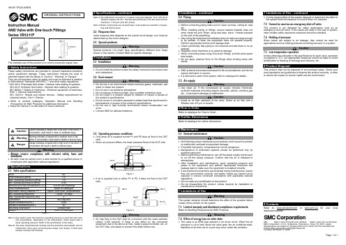
VR12F-TF222-005ENPage 1 of 1Instruction ManualAND Valve with One-touch FittingsThe intended use of this product is to control pneumatic signal lines.These safety instructions are intended to prevent hazardous situations and/or equipment damage. These instructions indicate the level of potential hazard with the labels of “Caution,” “Warning” or “Danger.” They are all important notes for safety and must be followed in addition to International Standards (ISO/IEC) *1), and other safety regulations. *1)ISO 4414: Pneumatic fluid power - General rules relating to systems. ISO 4413: Hydraulic fluid power - General rules relating to systems.IEC 60204-1: Safety of machinery - Electrical equipment of machines. (Part 1: General requirements)ISO 10218-1: Robots and robotic devices - Safety requirements for industrial robots - Part 1: Robots.• Refer to product catalogue, Operation Manual and Handling Precautions for SMC Products for additional information. • Keep this manual in a safe place for future reference.Warning • Always ensure compliance with relevant safety laws and standards.• All work must be carried out in a safe manner by a qualified person in compliance with applicable national regulations.2 SpecificationsNote 1) Use caution when the maximum operating pressure is used with soft nylonand polyurethane. Depending on the temperature, these tubes have a lower operating pressure. Refer to the specification of the tubes.Note 2) Two axes (horizontal and vertical) and two directions were tested, and nomalfunction of the valve occurred (pulse shape: sine shape), 3 times (test sample mounted with bracket).Note 3) No malfunction occurred in a sweep cycle test between 10 to 150 Hz atvibration sweep 0.35 mm. The test was performed in the two axes and two directions, 7 min per cycle (20 cycles).Note 4) Brass components are all electroless nickel plated as standard. (Copper-free and fluorine-free)2.2 Response timeValve response time depends on the overall circuit design, so it must be determined by the circuit designer. 2.3 Special productsWarningSpecial products (-X) might have specifications different from those shown in this section. Contact SMC for specific drawings.3 Installation3.1 InstallationWarning• Do not install the product unless the safety instructions have been read and understood. 3.2 EnvironmentWarning• Do not use in an environment where corrosive gases, chemicals, salt water or steam are present.• Do not use in an explosive atmosphere.• Do not expose to direct sunlight. Use a suitable protective cover.• Do not install in a location subject to vibration or impact in excess of the product’s specifications.• Do not mount in a location exposed to radiant heat that would result in temperatures in excess of the product’s specifications.• Do not use in high humidity environment where condensation can occur.• Contact SMC for altitude limitations.3.3 Operating pressure conditions• Only when air is supplied to both P1 and P2 does air flow to the OUT side.• When air pressure differs, the lower pressure flows to the OUT side.Figure 1.• If air is supplied only to either P1 or P2, it does not flow to the OUT side.Figure 2.Warning• Air may flow to the OUT side for a moment until the valve switches (About 1/100 second). If there is any effect on the connected equipment due to the above air flow, install a speed controller, etc, on the OUT side, and adjust to prevent this effect before use.3.4 PipingCaution• Before connecting piping make sure to clean up chips, cutting oil, dust etc.• When installing piping or fittings, ensure sealant material does not enter inside the port. When using seal tape, leave 1 thread exposed on the end of the pipe/fitting.• Stop using the equipment immediately when air leaks are large enough to be audible, or when the equipment does not operate properly. Perform appropriate function and leakage tests.• Check periodically that piping is not loosened and that there is no air leakage.• Regularly check that there is no external damage.• When connecting tubes using One-touch fittings, provide some spare tube length.• Do not apply external force to the fittings when binding tubes with bands.Caution• SMC products have been lubricated for life at manufacture, and do not require lubrication in service.• If a lubricant is used in the system, refer to catalogue for details. 3.5 Air supplyWarning• Use clean air. If the compressed air supply includes chemicals, synthetic materials (including organic solvents), salinity, corrosive gas etc., it can lead to damage or malfunction.Caution• Install an air filter upstream of the valve. Select an air filter with a filtration size of 5 μm or smaller.4 How to OrderRefer to catalogue for ‘How to Order’.5 Outline DimensionsRefer to catalogue for outline dimensions.6 Maintenance6.1 General maintenanceCaution• Not following proper maintenance procedures could cause the product to malfunction and lead to equipment damage.• If handled improperly, compressed air can be dangerous.• Maintenance of pneumatic systems should be performed only by qualified personnel.• Before performing maintenance, turn off the power supply and be sure to cut off the supply pressure. Confirm that the air is released to atmosphere.• After installation and maintenance, apply operating pressure and power to the equipment and perform appropriate functional and leakage tests to make sure the equipment is installed correctly.• If any electrical connections are disturbed during maintenance, ensure they are reconnected correctly, and safety checks are carried out as required to ensure continued compliance with applicable national regulations.• Do not make any modification to the product.• Do not disassemble the product, unless required by installation or maintenance instructions.7 Limitations of UseWarningThe system designer should determine the effect of the possible failure modes of the product on the system.7.1 Limited warranty and disclaimer/compliance requirements Refer to Handling Precautions for SMC Products.Warning7.2 Effect of energy loss on valve state• The valve is an AND logic element in an all-air circuit. When the air pressure is cut to both inputs the valve goes into an undefined state. Backflow of air from out to in port may occur under this condition.• It is the responsibility of the system designer to determine the effect in the system when air pressure is cut and when it is restored. 7.3 Cannot be used as an emergency shut-off valveThis product is not designed for safety applications such as an emergency shut-off valve. If the valves are used in this type of system, other reliable safety assurance measures should be adopted.7.4 Holding of pressureSince valves are subject to air leakage, they cannot be used for applications such as holding pressure (including vacuum) in a system.Caution7.5 Low temperature operationUnless otherwise indicated in the specifications for each valve, operation is possible to -5˚C, but appropriate m easures should be taken to avoid solidification or freezing of drainage and moisture, etc.8 Product DisposalThis product shall not be disposed of as municipal waste. Check your local regulations and guidelines to dispose this product correctly, in order to reduce the impact on human health and the environment.9 ContactsRefer to or www.smc.eu for your local distributor/importer.URL : https:// (Global) https:// www.smc.eu (Europe) SMC Corporation, 4-14-1, Sotokanda, Chiyoda-ku, Tokyo 101-0021, JapanSpecifications are subject to change without prior notice from the manufacturer. © 2022 SMC Corporation All Rights Reserved. Template DKP50047-F-085MORIGINAL INSTRUCTIONS2 (OUT)(IN) 1 (IN) 1IN P 1 IN P 2 OUT OUTOUT IN P 1 IN P 2 IN P 1 IN P 2。
- 1、下载文档前请自行甄别文档内容的完整性,平台不提供额外的编辑、内容补充、找答案等附加服务。
- 2、"仅部分预览"的文档,不可在线预览部分如存在完整性等问题,可反馈申请退款(可完整预览的文档不适用该条件!)。
- 3、如文档侵犯您的权益,请联系客服反馈,我们会尽快为您处理(人工客服工作时间:9:00-18:30)。
产品名称:进口SMC旋转气缸说明书
SMC气缸引导活塞在其中进行直线往复运动的圆筒形金属机件。
工质在发动机气缸中通过膨胀将热能转化为机械能;气体在压缩机气缸中接受活塞压缩而提高压力。
涡轮机、旋转活塞式发动机等的壳体通常也称“气缸”。
气缸的应用领域:印刷(张力控制)、半导体(点焊机、芯片研磨)、自动化控制、机器人等等,气压传动中将压缩气体的压力能转换为机械能的气动执行元件。
气缸有作往复直线运动的和作往复摆动的两类(见图)。
作往复直线运动的气缸又可分为单作用、双作用、膜片式和冲击气缸4种。
将压缩空气的压力能转换为机械能,驱动机构作直线往复运动、摆动和旋转运动,直线运动往复运动的气缸、摆动运动的摆动气缸、气爪等。