基本 RIP 配置
RIP配置实验
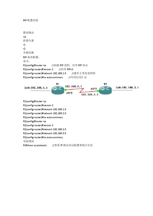
RIP配置实验静态路由rip距离矢量r1r2负载均衡RIP基本配置:命令:R1(config)#router rip //创建RIP进程,启用RIP协议R1(config-router)#version 2 //启用RIPv2R1(config-router)#network 192.168.1.0 //通告主类直连网段R1(config-router)#no auto-summary //关闭自动汇总R1(config)#router ripR1(config-router)#version 2R1(config-router)#network 192.168.1.0R1(config-router)#network 192.168.2.0R1(config-router)#no auto-summaryR2(config)#router ripR2(config-router)#version 2R2(config-router)#network 192.168.2.0R2(config-router)#network 192.168.3.0R2(config-router)#no auto-summary实验调试R1#show ip protocols //查看IP路由协议配置和统计信息R1#debug ip rip //查看RIP路由协议的动态更新过程R1#clear ip route *RIPv1、RIPv2兼容试验:接口特性优于进程特性,对于本实验,如果在进程中配置了(version 1或version 2),但是在接口上配置了ip rip receive version 1 2,则版本1和版本2的路由更新该接口都可以接收。
send receive默认模式: 1 1、2RIPv1: 1 1RIPv2: 2 2命令:R2(config-if)#ip rip send version 1 2 //设置R2即发送v1又发送v2R2(config-if)#ip rip receive version 1 2 //设置R2即接收v1又接收v2基本配置略。
RIP基本配置

RIP基本配置实验拓扑:实验环境:路由器两台R1、R2主机:Host1、Host2实验步骤:1.主机IP地址配置:2.基本接口配置:R1:[H3C]sysname R1[R1]int s1/0[R1-Serial1/0]ip add 192.168.1.1 255.255.255.0 [R1-Serial1/0]undo shutdown[R1-Serial1/0]quit[R1]int g0/0[R1-GigabitEthernet0/0]ip add 192.168.0.1 255.255.255.0[R1-GigabitEthernet0/0]undo shutdown[R1-GigabitEthernet0/0]R2:<H3C>system-viewSystem View: return to User View with Ctrl+Z.[H3C]sysname R2[R2]int s1/0[R2-Serial1/0]ip add 192.168.1.2 255.255.255.0[R2-Serial1/0]undo shutdown[R2-Serial1/0]quit[R2]int g0/0[R2-GigabitEthernet0/0]ip add 192.168.2.1 255.255.255.0[R2-GigabitEthernet0/0]undo shutdown[R2-GigabitEthernet0/0]使用displayer ip routing-table查看路由表:R1通过路由学到了直连的路由及网段-192.168.0.0/24、192.168.0.1/32、192.168.1.0/24、192.168.1.0/32、192.168.1.1/32、192.168.1.2/32,但是发现没有学到对端路由器192.168.2.0/24网段R2通过路由学到了直连的路由及网段-192.168.1.0/24、192.168.1.0/32、192.168.2.0/32、192.168.2.0/24、192.168.2.1/32、,但是发现没有学到对端路由器192.168.0.0/24网段在Hots1上使用ping命令测试网络连通性:C:\Users\qikang>ping -S 192.168.0.2 192.168.0.1正在Ping 192.168.0.1 从192.168.0.2 具有32 字节的数据:来自192.168.0.1 的回复: 字节=32 时间<1ms TTL=255来自192.168.0.1 的回复: 字节=32 时间<1ms TTL=255来自192.168.0.1 的回复: 字节=32 时间<1ms TTL=255来自192.168.0.1 的回复: 字节=32 时间<1ms TTL=255192.168.0.1 的Ping 统计信息:数据包: 已发送= 4,已接收= 4,丢失= 0 (0% 丢失),往返行程的估计时间(以毫秒为单位):最短= 0ms,最长= 0ms,平均= 0msC:\Users\qikang>ping -S 192.168.0.2 192.168.1.1正在Ping 192.168.1.1 从192.168.0.2 具有32 字节的数据:来自192.168.1.1 的回复: 字节=32 时间<1ms TTL=255来自192.168.1.1 的回复: 字节=32 时间<1ms TTL=255来自192.168.1.1 的回复: 字节=32 时间<1ms TTL=255来自192.168.1.1 的回复: 字节=32 时间<1ms TTL=255192.168.1.1 的Ping 统计信息:数据包: 已发送= 4,已接收= 4,丢失= 0 (0% 丢失),往返行程的估计时间(以毫秒为单位):最短= 0ms,最长= 0ms,平均= 0msC:\Users\qikang>ping -S 192.168.0.2 192.168.1.2正在Ping 192.168.1.2 从192.168.0.2 具有32 字节的数据:请求超时。
实验4.3 RIP协议基本配置
实验4.3 RIP 协议基本配置*【实验目的】•理解RIP 的基本配置【实验过程】假设在校园网在地理上分为 2 个区域,每个区域内分别有一台路由器连接了 2 个子网,需要将两台路由器通过以太网链路连接在一起并进行适当的配置,以实现这 4 个子网之间的互联互通。
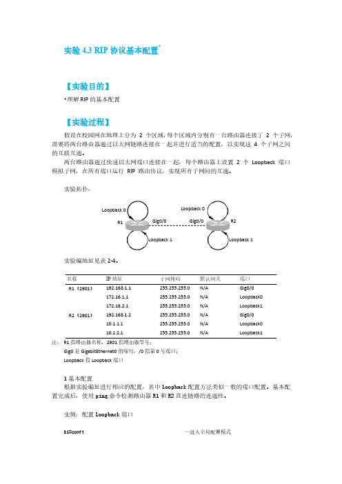
两台路由器通过快速以太网端口连接在一起,每个路由器上设置 2 个 Loopback 端口模拟子网,在所有端口运行 RIP 路由协议,实现所有子网间的互通。
实验拓扑:实验编地址见表2-4。
名称 IP 地址 子网掩码 默认网关 端口 R1(2901) 192.168.1.1 255.255.255.0 N/A Gig0/0 172.16.1.1 255.255.255.0 N/A Loopback0172.16.2.1 255.255.255.0 N/A Loopback1 R2(2901) 192.168.1.2 255.255.255.0 N/A Gig0/0 10.1.1.1 255.255.255.0 N/A Loopback010.1.2.1255.255.255.0N/ALoopback1注: R1指路由器名称,2901指路由器型号;Gig0是GigabitEthernet0的缩写,/0指第0号端口; Loopback 指Loopback 端口1基本配置根据实验编址进行相应的配置,其中Loopback 配置方法类似一般的端口配置。
基本配置完成后,使用ping 命令检测路由器R1和R2直连链路的连通性。
实例:配置Loopback 端口R1#conf t~进入全局配置模式Gig0/0Loopback 0R1R2 Gig0/0Loopback 0Loopback 1Loopback 1Enter configuration commands, one per line. End with CNTL/Z.R1(config)#int Loopback0~进入端口配置模式R1(config-if)#ip address 172.16.1.1 255.255.255.0 ~配置端口IP地址,掩码R1(config-if)#no shutdown~开启该端口(非常重要!)%LINK-5-CHANGED: Interface Loopback0, changed state to upR1(config-if)#end~结束配置%SYS-5-CONFIG_I: Configured from console by consoleR1#show int loopback0~查看端口状态Loopback0 is up, line protocol is up (connected)Hardware is LoopbackInternet address is 172.16.1.1/24 ~显示IP地址配置正确•••R1#Loopback是路由器软件虚拟的端口,是逻辑上的一个端口,它没有物理的存在。
实验8 基本的RIP V2配置

实验名称基本的RIP V2配置。
实验目的掌握在路由器和三层交换机上配置RIP V2。
实现功能通过RIP2协议实现网络的互连互通,从而实现信息的共享和传递。
实验设备锐捷R2624路由器2台,网线2根,V35线缆1对。
背景描述一个公司总部和销售公司分处在两个地方,现为了搭建公司的OA系统,需要将两地的网络连在一起。
本实验以两台R2624路由器为例来模拟该环境,路由器1和2通过V35线缆连接。
PC1连着Router1,PC2连着Router2.PC1的网络地址为192.168.11.0/24,两个路由器的串口地址为192.168.12.0/24,PC2的网络地址为192.168.13.0/24.实验步骤1.对Router1进行基本配置:configure terminalhostname Router1interface fa1/0ip address 192.168.11.1 255.255.255.0no shutdowninterface S1/2ip address 192.168.12.1 255.255.255.0clock rate 64000no shutdownexitshow ip interface brief2.对Router2进行基本配置:configure terminalhostname Router2interface fa1/0ip address 192.168.13.1 255.255.255.0no shutdowninterface S1/2ip address 192.168.12.2 255.255.255.0no shutdownexitshow ip interface brief3.对Router1配置路由协议rip2:Configure terminalRouter rip(开启RIP路由协议)Version 2(定义RIP路由协议的版本为2)Network 192.168.11.0(定义与本路由器相连的关联网络)Network 192.168.12.0(定义与本路由器相连的关联网络)EndShow ip route(显示路由表)4.对Router2配置路由协议rip2:Configure terminalRouter ripVersion 2Network 192.168.12.0Network 192.168.13.0EndShow ip route5.测试网络的连通性,将两台计算机的IP地址设为所属网段的地址,网关设为所连路由器的以太网口的地址。
RIP配置及排错大全

查看接口状态
总结词
检查RIP协议运行的接口是否正常工作
详细描述
使用命令`show interfaces`查看接口状态, 确保接口处于up状态并且没有错误。
使用debug命令
总结词
诊断RIP协议的通信问题
详细描述
使用debug命令如`debug ip rip`来开启RIP调试,观察RIP协议的通信过程,查找可能 的问题。
RIP版本1和版本2的比较
RIP版本2支持认证和子网掩码,而RIP版本1不支持。
RIP版本2的认证
RIP版本2支持明文和MD5认证,可以增加网络的安全性。
RIP的子网掩码
RIP版本2使用子网掩码来确定路由的下一跳地址。
RIP的广播模式和网络模式
在RIP的广播模式下,路由器会向所有邻居发送路由更新;在网络模 式下,路由器会向所有邻居发送请求,请求邻居发送路由更新。
简单性 配置简单
RIP与OSPF比较
复杂性
02
OSPF
01 03
配置相对复杂
资源占用较多
04
05
适用大型网络
RIP与EIGRP比较
RIP
01
02
路由汇总
路由协议中的汇总路由可以减少路由器的 资源占用和网络中的路由条目数量,提高
网络的稳定性。
03
不使用路由汇总
05
04
EIGRP
06
EIGRP是一种相对复杂的路由协议,它不 使用路由汇总,而是通过其他方式来减少 路由器的资源占用和网络中的路由条目数 量。
在小型企业网络中,RIP协议配置相对 简单,只需要在相关设备上启用RIP协 议,并正确配置网络接口即可。
校园网络
01
RIP基本配置

拓扑图的构建:# Simple labautostart = false[localhost][[7200]]image = C:\Program Files\Dynamips\images\unzip-c7200-js-mz.123-20.bin ram = 96nvram = 96disk0 = 64disk1 = 64npe = npe-400cnfg = Noneconfreg = 0x2102mmap = false#idlepc = 0x60490168(3640)#idlepc = 0x6068802cexec_area = 16[[ROUTER R1]]model = 7200s1/0 = R2 s1/0[[ROUTER R2]]model = 7200s1/1 = R3 s1/1[[ROUTER R3]]model = 7200配置步骤一:R1的配置:Router>enRouter#conf tRouter(config)#host R1R1(config)#no ip domain-loR1(config)#line con 0R1(config-line)#logg synR1(config-line)#exec-time 0 0R1(config-line)#exitR1(config)#R1(config)#int lo0R1(config-if)#ip add 1.1.1.1 255.255.255.0R1(config-if)#exitR1(config)#R1(config)#int s1/0R1(config-if)#ip add 192.168.12.1 255.255.255.0 R1(config-if)#clockrate 64000R1(config-if)#no shutR1(config-if)#exitR1(config)#R1(config)#router ripR1(config-router)#version 2R1(config-router)#no auto-summaryR1(config-router)#netw 1.0.0.0R1(config-router)#netw 192.168.12.0R1(config-router)#endR1#R2的配置:Router>enRouter#conf tRouter(config)#host R2R2(config)#no ip domain-loR2(config)#line con 0R2(config-line)#logg synR2(config-line)#exec-time 0 0R2(config-line)#exitR2(config)#R2(config)#int s1/0R2(config-if)#ip add 192.168.12.2 255.255.255.0 R2(config-if)#clockrate 64000R2(config-if)#no shutR2(config-if)#exitR2(config)#R2(config)#int s1/1R2(config-if)#ip add 192.168.23.2 255.255.255.0 R2(config-if)#clockrate 64000R2(config-if)#no shutR2(config-if)#exitR2(config)#R2(config)#router ripR2(config-router)#version 2R2(config-router)#no auto-summaryR2(config-router)#netw 192.168.12.0R2(config-router)#netw 192.168.23.0R2(config-router)#endR2#R3的配置:Router>enRouter#conf tRouter(config)#host R3R3(config)#no ip domain-loR3(config)#line con 0R3(config-line)#logg synR3(config-line)#exec-time 0 0R3(config-line)#exitR3(config)#R3(config)#int lo0R3(config-if)#ip add 3.3.3.3 255.255.255.0R3(config-if)#exitR3(config)#R3(config)#int s1/1R3(config-if)#ip add 192.168.23.3 255.255.255.0R3(config-if)#clockrate 64000R3(config-if)#no shutR3(config-if)#exitR3(config)#R3(config)#router ripR3(config-router)#version 2R3(config-router)#no auto-summaryR3(config-router)#netw 3.0.0.0R3(config-router)#netw 192.168.23.0R3(config-router)#endR3#配置步骤二(验证)R1#show ip routeCodes: C - connected, S - static, R - RIP, M - mobile, B - BGPD - EIGRP, EX - EIGRP external, O - OSPF, IA - OSPF inter areaN1 - OSPF NSSA external type 1, N2 - OSPF NSSA external type 2E1 - OSPF external type 1, E2 - OSPF external type 2i - IS-IS, su - IS-IS summary, L1 - IS-IS level-1, L2 - IS-IS level-2 ia - IS-IS inter area, * - candidate default, U - per-user static route o - ODR, P - periodic downloaded static routeGateway of last resort is not setC 192.168.12.0/24 is directly connected, Serial1/01.0.0.0/24 is subnetted, 1 subnetsC 1.1.1.0 is directly connected, Loopback03.0.0.0/24 is subnetted, 1 subnetsR 3.3.3.0 [120/2] via 192.168.12.2, 00:00:12, Serial1/0R 192.168.23.0/24 [120/1] via 192.168.12.2, 00:00:12, Serial1/0R1#R1#R1#ping 3.3.3.3 source 1.1.1.1Type escape sequence to abort.Sending 5, 100-byte ICMP Echos to 3.3.3.3, timeout is 2 seconds:Packet sent with a source address of 1.1.1.1!!!!!Success rate is 100 percent (5/5), round-trip min/avg/max = 12/37/60 msR1#R2#R2#show ip routeCodes: C - connected, S - static, R - RIP, M - mobile, B - BGPD - EIGRP, EX - EIGRP external, O - OSPF, IA - OSPF inter areaN1 - OSPF NSSA external type 1, N2 - OSPF NSSA external type 2E1 - OSPF external type 1, E2 - OSPF external type 2i - IS-IS, su - IS-IS summary, L1 - IS-IS level-1, L2 - IS-IS level-2 ia - IS-IS inter area, * - candidate default, U - per-user static route o - ODR, P - periodic downloaded static routeGateway of last resort is not setC 192.168.12.0/24 is directly connected, Serial1/01.0.0.0/24 is subnetted, 1 subnetsR 1.1.1.0 [120/1] via 192.168.12.1, 00:00:23, Serial1/03.0.0.0/24 is subnetted, 1 subnetsR 3.3.3.0 [120/1] via 192.168.23.3, 00:00:09, Serial1/1C 192.168.23.0/24 is directly connected, Serial1/1R2#R3#R3#show ip routeCodes: C - connected, S - static, R - RIP, M - mobile, B - BGPD - EIGRP, EX - EIGRP external, O - OSPF, IA - OSPF inter areaN1 - OSPF NSSA external type 1, N2 - OSPF NSSA external type 2E1 - OSPF external type 1, E2 - OSPF external type 2i - IS-IS, su - IS-IS summary, L1 - IS-IS level-1, L2 - IS-IS level-2 ia - IS-IS inter area, * - candidate default, U - per-user static routeo - ODR, P - periodic downloaded static routeGateway of last resort is not setR 192.168.12.0/24 [120/1] via 192.168.23.2, 00:00:08, Serial1/11.0.0.0/24 is subnetted, 1 subnetsR 1.1.1.0 [120/2] via 192.168.23.2, 00:00:08, Serial1/13.0.0.0/24 is subnetted, 1 subnetsC 3.3.3.0 is directly connected, Loopback0C 192.168.23.0/24 is directly connected, Serial1/1R3#R3#R3#ping 1.1.1.1 source 3.3.3.3Type escape sequence to abort.Sending 5, 100-byte ICMP Echos to 1.1.1.1, timeout is 2 seconds: Packet sent with a source address of 3.3.3.3!!!!!Success rate is 100 percent (5/5), round-trip min/avg/max = 16/36/52 ms R3#。
RIP基本配置

背景描述
• 假设校园网通过一台三层交换机连接到校园网出口路 由器,路由器再与校园网外的另一路由器连接,现在 要做适当配置,实现校园网内部与校园网外表主机相 互通讯。 • 本实验以两台R2624路由器、1台S3550三层交换机 为例。S3550上划分VLAN10和VLAN50,其中 VLAN10用于连接Router1,VLAN50用于连接校 园网主机。 • 路由器分别命名为Router1和Router2,路由器之间 提高串口采用V35 DCE/DTE电缆连接。 • PC1的IP和网关分别为172.16.5.11和172.16.5.1, PC2的IP和网关分别为172.16.3.22和172.16.1.1, 网络掩码都是255.255.255.0
步骤3 验证3台设备路由表
• 验证3台设备路由表,查看是否自动学习 其他网段的路由信息。 • 在每台设备特权模式下:使用show ip route查看设备路由表。
步骤4. 测试网络连通性。
• 在PC1、PC2上设置好IP和网关,然后 在PC1上pingPC2或在PC2上 pingPC1. • 网关就是pc与之相连接口的IP
实验拓扑
s3550
Vlan10
R1
R2
F0 F0/5 Vlan50 F0/1 S1DT S1DC E E R1.F0=172.16.1.1/24 R1.S1=172.16.2.1/24 R2.F0=172.16.3.1/24 R2.S1=172.16.2.2/24 S3550.vlan10=172.16.1.2/24 S3550.vlan50=172.16.5.1/24 PC1IP=172.16.5.11/24 PC1GW=172.16.5.1 PC2IP=172.16.3.22/24 PC2GW=172.16.3.1 F0
基本RIP配置

基本RIP 配置任务1:准备网络任务2:执行基本路由器配置。
任务3:配置并激活串行地址和以太网地址。
步骤1:配置R1、R2 和R3 的接口。
使用拓扑图下方表格中的 IP 地址配置R1、R2 和R3 路由器上的接口。
步骤2:检验IP 编址和接口。
使用show ip interface brief 命令检验IP 编址是否正确、接口是否处于活动状态。
完成后,务必将运行配置保存到路由器的NVRAM 中。
步骤3:配置PC1、PC2 和PC3 的以太网接口。
使用拓扑图下方表格中的IP 地址和默认网关配置PC1、PC2 和PC3 的以太网接口。
步骤4:通过从PC ping 默认网关来测试PC 配置。
任务4:配置RIP。
步骤1:启用动态路由。
要启用动态路由协议,请进入全局配置模式并使用router 命令。
在全局配置提示符处输入router ? 可查看路由器上可用路由协议的列表。
要启用RIP,请在全局配置模式下输入命令router rip。
R1(config)#router ripR1(config-router)#步骤2:输入有类网络地址。
进入路由配置模式,使用network 命令输入每个直连网络的有类网络地址。
R1(config-router)#network 192.168.1.0R1(config-router)#network 192.168.2.0R1(config-router)#步骤3:使用router rip 和network 命令在R2 路由器上配置RIP。
R2(config)#router ripR2(config-router)#network 192.168.2.0R2(config-router)#network 192.168.3.0R2(config-router)#network 192.168.4.0R2(config-router)#end%SYS-5-CONFIG_I:Configured from console by consoleR2#copy run start完成RIP 配置后,返回特权执行模式并将当前配置保存到NVRAM 中。
- 1、下载文档前请自行甄别文档内容的完整性,平台不提供额外的编辑、内容补充、找答案等附加服务。
- 2、"仅部分预览"的文档,不可在线预览部分如存在完整性等问题,可反馈申请退款(可完整预览的文档不适用该条件!)。
- 3、如文档侵犯您的权益,请联系客服反馈,我们会尽快为您处理(人工客服工作时间:9:00-18:30)。
云南大学软件学院实验报告实验5.6.1:基本 RIP 配置场景A任务1:准备网络。
步骤1:构建一个类似拓扑图所示的网络。
您可以在实验中使用任何路由器,只要它具备拓扑图中所要求的接口即可。
注意:如果您使用1700、2500 或2600 路由器,则路由器输出和接口描述会与本文档中提供的有所不同。
步骤2:清除路由器上的现有配置任务2:执行基本路由器配置。
根据下面的指导执行R1、R2 和R3 路由器的基本配置:1.配置路由器路路路。
2. 禁用DNS 查查。
3. 配置执行配配口令。
4. 配置置置置息标置。
5. 配置配配配连接的口令。
R1(config)# line console 0R1(config-line)# password classR1(config-line)# login6.配置VTY 连接的口令。
R1(config-line)# line vty 0 15R1(config-line)# password classR1(config-line)# login任务3:配置并激活串行地址和以太网地址。
步骤1:配置R1、R2 和R3 的接口。
使用拓扑图下方表格中的IP 地址配置R1、R2 和R3 路由器上的接口。
步骤2:检验IP 编址和接口。
使用show ip interface brief 命令检验IP 编址是否正确、接口是否处于活动状态。
完成后,务必将运行配置保存到路由器的NVRAM 中。
步骤3:配置PC1、PC2 和PC3 的以太网接口。
使用拓扑图下方表格中的IP 地址和默认网关配置PC1、PC2 和PC3 的以太网接口。
步骤4:通过从PC ping 默认网关来测试PC 配置。
任务4:配置RIP。
步骤1:启用动态路由。
要启用动态路由协议,请进入全局配置配配并使用router 命令。
在全局配置提示符处输入router ? 可查看路由器上可用路由协议的列表。
要启用RIP,请在全局配置配配下输入命令router rip。
R1(config)#router ripR1(config-router)#步骤2:输入有类网络地址。
进入路由配置配配,使用network 命令输入每个直连网络的有类网络地址。
R1(config-router)#network 192.168.1.0R1(config-router)#network 192.168.2.0R1(config-router)#network 命令的作用如下:•对属于该网络的所有接口启用RIP。
这些接口将开始发送和接收RIP 更新。
•在每30 秒一次的RIP 路由更新中向其它路由器通告该网络。
完成RIP 配置后,返回特权执行配配并将置前配置保存到NVRAM 中。
R1(config-router)#end%SYS-5-CONFIG_I:Configured from console by consoleR1#copy run start步骤3:使用router rip 和network 命令在R2 路由器上配置RIP。
R2(config)#router ripR2(config-router)#network 192.168.2.0R2(config-router)#network 192.168.3.0R2(config-router)#network 192.168.4.0R2(config-router)#end%SYS-5-CONFIG_I:Configured from console by consoleR2#copy run start完成RIP 配置后,返回特权执行配配并将置前配置保存到NVRAM 中。
步骤4:使用router rip 和network 命令在R3 路由器上配置RIP。
R3(config)#router ripR3(config-router)#network 192.168.4.0R3(config-router)#network 192.168.5.0R3(config-router)#end%SYS-5-CONFIG_I:Configured from console by consoleR3#copy run start完成RIP 配置后,返回特权执行配配并将置前配置保存到NVRAM 中。
任务5:检验RIP 路由。
步骤1:使用show ip route 命令检验是否每配路由器的路由表中都包含拓扑图中的所有网络。
通过RIP 获知的路由在路由表中标记有代码R。
如果路由表未收敛于如图所示的状态,请对您的配置进行故障排除。
您是否确定所配置的接口处于活动状态?您是否正确配置了RIP?返回到任务3 和任务4 以回顾达到收敛所需的步骤R1#show ip routeCodes: C - connected, S - static, I - IGRP, R - RIP, M - mobile, B - BGPD - EIGRP, EX - EIGRP external, O - OSPF, IA - OSPF inter areaN1 - OSPF NSSA external type 1, N2 - OSPF NSSA external type 2E1 - OSPF external type 1, E2 - OSPF external type 2, E - EGPi - IS-IS, L1 - IS-IS level-1, L2 - IS-IS level-2, ia - IS-IS inter area* - candidate default, U - per-user static route, o - ODRP - periodic downloaded static routeGateway of last resort is not setC 192.168.1.0/24 is directly connected, FastEthernet0/0C 192.168.2.0/24 is directly connected, Serial0/0/0R 192.168.3.0/24 [120/1] via 192.168.2.2, 00:00:04, Serial0/0/0R 192.168.4.0/24 [120/1] via 192.168.2.2, 00:00:04, Serial0/0/0R 192.168.5.0/24 [120/2] via 192.168.2.2, 00:00:04, Serial0/0/0R1#R2#show ip routeR 192.168.1.0/24 [120/1] via 192.168.2.1, 00:00:22, Serial0/0/0C 192.168.2.0/24 is directly connected, Serial0/0/0C 192.168.3.0/24 is directly connected, FastEthernet0/0C 192.168.4.0/24 is directly connected, Serial0/0/1R 192.168.5.0/24 [120/1] via 192.168.4.1, 00:00:23, Serial0/0/1R2#R3#show ip routeR 192.168.1.0/24 [120/2] via 192.168.4.2, 00:00:18, Serial0/0/1R 192.168.2.0/24 [120/1] via 192.168.4.2, 00:00:18, Serial0/0/1R 192.168.3.0/24 [120/1] via 192.168.4.2, 00:00:18, Serial0/0/1C 192.168.4.0/24 is directly connected, Serial0/0/1C 192.168.5.0/24 is directly connected, FastEthernet0/0R3#步骤2:使用show ip protocols 命令查看有关路由进程的信息。
show ip protocols 命令可用来查看有关路由器上正在运行的路由进程的信息。
其输出可用于检验大多数RIP 参数,从而确认:•是否已配置RIP 路由•发送和接收RIP 更新的接口是否正确•路由器通告的网络是否正确•RIP 邻居是否发送了更新R1#show ip protocolsRouting Protocol is "rip"Sending updates every 30 seconds, next due in 16 secondsInvalid after 180 seconds, hold down 180, flushed after 240Outgoing update filter list for all interfaces is not setIncoming update filter list for all interfaces is not setRedistributing: ripDefault version control: send version 1, receive any versionInterface Send Recv Triggered RIP Key-chainFastEthernet0/0 1 2 1Serial0/0/0 1 2 1Automatic network summarization is in effectMaximum path: 4Routing for Networks:192.168.1.0192.168.2.0Passive Interface(s):Routing Information Sources:Gateway Distance Last Update 192.168.2.2 120 Distance: (default is 120)R1#R1 确实配置了RIP。
R1 正在FastEthernet0/0 和Serial0/0/0 接口上发送和接收RIP 更新。
R1 正在通告网络192.168.1.0 和192.168.2.0。
R1 有一个路由信息源。
R2 正在向R1 发送更新。
步骤3:使用debug ip rip 命令查看发送和接收的RIP 置息。
Rip 更新每30 秒钟发送一次,所以您可能需要稍等片刻才能看到调试信息。
R1#debug ip ripR1#RIP: received v1 update from 192.168.2.2 on Serial0/0/0192.168.3.0 in 1 hops192.168.4.0 in 1 hops192.168.5.0 in 2 hopsRIP: sending v1 update to 255.255.255.255 via FastEthernet0/0 (192.168.1.1)RIP: build update entriesnetwork 192.168.2.0 metric 1network 192.168.3.0 metric 2network 192.168.4.0 metric 2network 192.168.5.0 metric 3RIP: sending v1 update to 255.255.255.255 via Serial0/0/0 (192.168.2.1)RIP: build update entriesnetwork 192.168.1.0 metric 1调试输出显示R1 接收到一条来自R2 的更新。