studer 961962 调音台资料
雅马哈01V96V2数字调音台进阶应用指南_五_
在《雅马哈01V 6V2数字调音台进阶应用指南(四)》[1]中讨论了内部效果器的使用,并说明了效果库的内容。
接下来继续深入地了解其更为详尽的设置与操作。
这部分对其输入/输出通道的一些主要设置的灵活应用进行详解。
1 输入通道的门限动态处理在01V 6的每个输入通道,都有一个单独的噪声门(GATE)可用,相当于内置了32台噪声门设备已。
在多支话筒同时打开的情况下,合理地设置通道噪声门,可避免话筒线路带来的本底噪声,以及多支话筒并用造成的传声增益下降易啸叫的问题。
作用类似智能话筒混音器。
01V 6的门限触发还可由非本通道信号来实现(其他输入通道或AUX 发送通道)。
利用这个功能,将门限类型设为限制器,还可实现类似会议系统的主席优先模式,即某路话筒的信号会触发其他所有话筒信号的限幅。
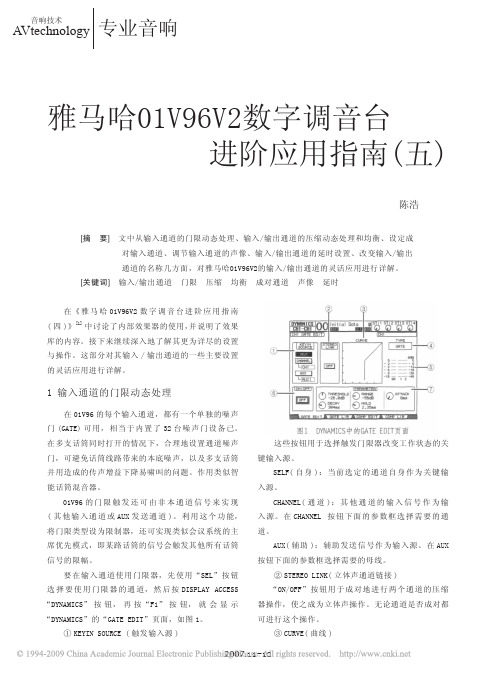
要在输入通道使用门限器,先使用“SEL”按钮选择要使用门限器的通道,然后按DISPLAY ACCESS “DYNAMICS”按钮,再按“F1”按钮,就会显示“DYNAMICS”的“GATE EDIT”页面,如图1。
①KEYIN SOURCE (触发输入源)这些按钮用于选择触发门限器改变工作状态的关键输入源。
SELF(自身):当前选定的通道自身作为关键输入源。
CHANNEL(通道):其他通道的输入信号作为输入源。
在CHANNEL 按钮下面的参数框选择需要的通道。
AUX(辅助):辅助发送信号作为输入源。
在AUX 按钮下面的参数框选择需要的母线。
②STEREO LINK(立体声通道链接)“ON/OFF”按钮用于成对地进行两个通道的压缩器操作,使之成为立体声操作。
无论通道是否成对都可进行这个操作。
③CURVE(曲线)雅马哈01V 6V2数字调音台进阶应用指南(五)图1 DYNAMICS中的GATE EDIT页面[摘 要] 文中从输入通道的门限动态处理、输入/输出通道的压缩动态处理和均衡、设定成 对输入通道、调节输入通道的声像、输入/输出通道的延时设置、改变输入/输出 通道的名称几方面,对雅马哈01V 6V2的输入/输出通道的灵活应用进行详解。
studer_Vista_8_prodinfo_en[1]
![studer_Vista_8_prodinfo_en[1]](https://img.taocdn.com/s3/m/1dc38685bceb19e8b8f6ba1c.png)
Studer Vista 8Digital Audio Console Information29th July 20041INTRODUCTION (3)2GENERAL SYSTEM OVERVIEW (3)2.1 S YSTEM B LOCK D IAGRAM (3)2.1.1Block Diagram showing system utlising D21m IO System (3)2.2 C ONTROL S URFACE (V ISTA 8) (4)•Momentary/Latching Activation of all Buttons (5)•Ganging (5)•Fast Copy/Paste and Half-Lit Keys (5)•Banking with Scrolling Navigation (5)C ORE (6)2.3 DSP2.4 I NPUT/O UTPUT S YSTEM (7)2.4.1Available D21m Audio IO Cards (7)2.4.2D21m Stagebox System (7)2.5 M ONITORING, T ALKBACK AND S IGNALLING (8)2.5.1Monitoring (8)2.5.2Talkback and Signalling (8)2.6 E XTERNAL S YNCHRONISATION (9)3TROUBLESHOOTING (9)3.1 S YSTEM S URVEYOR (9)3.2 S ERVICE I SSUES (10)4REDUNDANCY (11)4.1.1Power Supplies (11)4.1.2DSP Core (11)4.1.3MADI Links (12)4.1.4Control System (12)4.1.5Control Surface (12)4.1.6Mastersync Unit (13)D ESCRIPTION (13)4.2 N-15TECHNICAL SPECS (14)5.1 V ISTA 8 C ONTROL S URFACE D IMENSIONS (14)5.2 P OWER C ONSUMPTION (14)1 IntroductionThis document outlines some of the key features of the Studer Vista 8 Digital Audio Console.2 General System OverviewThe system structure of the Vista 8 Digital Console can be separated into 5 main areas:1. Control Surface2. DSP Core3. IO4. Monitoring & Signalling5. External Synchronisation2.1 System Block Diagram2.1.1 Block Diagram showing system utlising D21m IO SystemGlobal Wiring Overview Vista 8 (with D21m I/O)Vista 8 Desk (with built-in Control System)TB Int D21m StageboxStagebox IO(Option: Mastersync Unit)PLEASE NOTE: This is a general System Block Diagram. Actual number of D21 IO frames will depend on customer requirements.2.2 Control Surface (Vista 8)The Control Surface of the Vista 8 is shown below (only 1 fader bay shown):The control surface features the industry acclaimed Vistonics User Interface which offers a “where you look is where you control” philosophy. The Studer developed Vistonics technology mounts rotary controls and switches on TFT Screens. This then offers the user the benefits of screen technology (Touchscreen, colour, icons and text) without the limitations of having to access physical controls away from the where the control is displayed. A touch and access philosophy combined with Channel strip orientated operation offers a friendly and intuitive operating concept.This extremely intuitive and fast to learn operational concept is further enhanced by 4 other key operational features that frees the users mind from working on the console and allows more thought to be placed on the work at hand. These key features are:• Momentary/Latching Activation of all ButtonsThe console recognizes and senses the button-push duration and responds accordingly. The buttons therefore act momentarily or latchingly depending on how they were pressed (pressed-and-held or briefly tapped). In addition to Talkback, PFL, EQ on/off, etc., the functions affected include those accessed by the touch-screen - such as viewing of audio function - as well as the monitoring source selectors and the machine control.• GangingThe ganging function in the mixer allows the operator to quickly apply functions to multiple channel strips because channels within the gang act as one. This can be used, for example, for Mute, Automation mode changes, faders, Bus assign and much more to increase speed and comfort in operation. Creating a gang over the console makes the set-up quick and easy.• Fast Copy/Paste and Half-Lit KeysThe console incorporates dedicated copy/paste keys for each audio function including EQ, dynamics, panorama and delay. A simple button-press in the original channel and another in the target channel copies the settings across. Copy/Paste is guided up by the half-lit buttons: if one button has been pressed and the desk is awaiting a second button-press, all available target buttons illuminate at half brightness until one of them has been selected. Also, complete channels can be cloned to one or many target channels. Setting up the Studer Vista 7 for a production becomes a quick and easy task. Non-productive time is reduced considerably.• Banking with Scrolling NavigationDSP channels not visible on the physical desk are accessed by scrolling the channels available in the DSP core. The channel order is freely assignable: channels can be grouped or even shown repeatedly on the surface. This ensures physical orientation on the desk so that the operator is always clearly informed as to what is happening. Channel Bays with, for example, the master channels can also be locked in place.The Vista 8 also includes a completely redesigned Control Bay. While talkback and monitoring functionality, trackball and a motorized joystick have been maintained from the previous Vista consoles, dedicated control elements have been introduced for operation of outputs. 12 motorizedfaders and a Vistonics™ screen with 40 rotaries have been added. Multiple user definable assignments of these 12 faders and Vistonics™ controls are possible to be recalled by one button press, giving up to 52 directly accessible level controls for controlling all sorts of outputs such as master, groups or matrix outputs. Two of the faders will act as “grand masters” without alternate pages, allowing instant influence on all console outputs if needed. The other 10 fader strips as well as all 40 rotaries with their pushbuttons will allow also SOLO/PFL, MUTE as well as TALKING to each masters individually. Metering has also been extended: 40 meters are visible on the Vistonics and the corresponding level controls are immediately available on the rotary controls next to them. Looking at levels and correcting them therefore is just a fraction of a second away.Another major improvement is the “reverse operation” of masters and their busses. Vista 8 can show all channels contributing to a specific master bus on the Vistonics™ screen and allows level adjustment of all those channels instantly - without physically accessing the contributing channels themselves on the fader bay.Furthermore the control group functionality (VCA style) will be extended to form control groups with different levels of control (hierarchical control groups). Each channel strip allows the possibility to flip a single fader to a second layer without flipping the whole console. Dynamic Automation is also a feature of the desk. You can boot the desk in one of two modes; Snapshot automation for live on-air or dynamic automation for production use. New dual colour metering is provided on each channel to give better headroom indication which is definable.2.3 DSP CoreThe DSP core of the Studer Vista 8 builds on Studer‘s well-proven digital technology. It incorporates an excellent reliability record and inspires a high degree of confidence enjoyed by the numerous users operating systems in mission-critical applications. The DSP core uses parallel processing architecture with integrated floating point circuitry and an internal word length of 40 bits. No overloads will ever occur within the console, since floating point architecture is even used in the summing busses. The system can be used in 48 kHz or 96 kHz mode.The DSP Core is based on modular cards and the more DSP cards that have been fitted in the core, the more DSP power is available. DSP Boards can have 8 AES IO incorporated per board.An offline Configuration Editor tool is also available which allows the available DSP Power to be reconfigured by the customer. This includes changing the number of channels, audio processing and bussing structure of the console for a particular project. Extensive import functions allows the user to adapt existing configurations to meet changing needs. In addition, the combination of modular DSP cards and the configuration editor means that future console expansion is as simple as adding more DSP cards and making new larger configurations with the configuration editor.2.4 Input/Output SystemThe D21m high-density audio interface system is like a hub to the Vista 8 DSP Core. The 19” Frame can hold up to 12 interface cards where audio is collected from or distributed to all standard professional industry audio formats.Up to 384 inputs and outputs from 12 audio card slots are collected in the center of the 3U D21m Frame where one or two High Density Cards can be placed. These cards provide the link to the DSP Core of the console using standard CAT 5 cable connections. Each connection carries up to 96 channels into the Performa DSP Core and 48 channels out in 24 bit 96Khz quality. The system automatically detects newly inserted cards and assigns the appropriate number of Input/Output channels to it. A status display on the front panel informs the user if a card is present or if the card has failed or been removed. The Frame may also be ordered with redundant power supplies. In addition, all D21m audio cards are hot-pluggable.2.4.1 Available D21m Audio IO Cards• Microphone Card: 4 x microphone Preamp with 24 bit Converter (split output available as standard)• AES/EBU Card: 8 x AES/EBU in and 8 x AES/EBU Out• AES/EBU Card with Input and Output SFC: Same as above but with asynchronous sampling Frequency converters on both inputs and outputs.• Line In Card: 8 channel D/A Converter Board (Specs?)• Line Out Card: 8 channel A/D Converter Board (Specs?)• ADAT Card: 2 optical input and 2 optical output interfaces• TDIF Board: 2 TDIF Interfaces• MADI IO Board: 1 x 56 or 64 channel MADI Input and Output. A Second input and output is available and can be used as a redundant MADI or to provide a split MADI signal of Output 1.2.4.2 D21m Stagebox SystemThe D21m Stagebox system utilises a D21m Hub which sits local (10m) to the DSP Core and stageboxes which collect all the remote IO signals and convert them to a single 56 or 64 channel MADI signal. The Hub then receives the MADI signals from the stageboxes and sends them to the DSP core via a single CAT 5 cable. The hub can handle up to a maximum of 6 stageboxes. A D21m Hub can also handle any of the local IO. Any stageboxes with Microphone Preamp cards will require some control data from the Vista Control Surface. This control data is first sent to the D21m Hub where the control data is merged with the MADI stream. The system can automatically detect stageboxes with microphones and send the correct Control Data from the desk making operational handling incredibly simple. This auto detection mechanism means that sharing stageboxes between different Consoles is extremely easy requiring no user administration.2.5 Monitoring, Talkback and SignallingA single 3U rack unit is utilised for housing all of the Monitoring and Signaling cards of the system.2.5.1 MonitoringThe monitoring is controlled in the analogue domain. Some fixed AES/EBU outputs are utilized from the Vista 8 DSP Core and are fed to converters built into the monitoring frame. 5.1 monitoring is standard on the Vista 8 with Dolby EX Monitoring as an option. The Control Room monitoring section on the control surface provides control of up to three different speaker systems (Two multi-channel and one stereo) and 76 source selectors. All internal digital sources can be assigned to any of the source selector keys as mono, stereo or multichannel sources. The 2 Studio Monitors are configurable in the same way as the CR Monitor section, although as standard only stereo studio loudspeaker feeds are supported. Surround studio feeds are available with a custom monitoring frame.A headphone socket is also available on the control surface for use in the control room.2.5.2 Talkback and SignallingAn extensive talkback system is implemented within the Vista. The talkback source can either be the built in desk operator microphone or an external producer microphone. Several destinations, such as buses, direct outs, auxillaries, groups and master outputs are available on block. The block diagram below shows the talkback and signaling possibilities of the Vista 8.Talkback and signaling blockdiagram2.6 External SynchronisationExternal digital synchronization of the console is provided by a Studer Mastersync Unit. This single 19 inch 1U unit will allow the console to be synchronized to an external video black burst, wordclock or AES signal.A second mastersync unit may be used as a redundant unit with an automatic switchover should a problem occur with the first unit.3 Troubleshooting3.1 System SurveyorThe software graphical controller has a built in real/time system surveyor. This surveyor monitors the status of all of the communication between the various parts of the system and provides a visual indication to the user of the status. This is extremely re-assuring for the user who not only has a continuous visual performance indication, but if there is a problem, clicking on the icon will show the user where problems have occurred. See the screenshot of the surveyor window below. It also surveys all of the IO racks and displays the status of each individual IO Card and Power supply in the D21m Frames.This is also extremely useful for service issues. A log file is also kept which logs any system errors. In some instances, this can then be sent to the factory (via e-mail) for fault finding assistance.3.2 Service IssuesAs far as the control surface is concerned, each bay is a single module which opens up like a car bonnet to access inside the console (See picture). All cable connections to the control surface are on the front of the console for easy access.The DSP, IO and monitoring are all made up of have modular cards.4 RedundancyThere are 5 areas where redundancy is available:Power suppliesDSP CoreMADI LinksComplete Control SystemControl SurfaceMastersync Unit4.1.1 Power SuppliesWithout exception, throughout all parts of the system redundant power supplies that automatically switch in case of failure of the primary supply are provided. This includes: Control SurfaceDSP CoreMonitoringAll I/O FramesControl System (Installed as standard)4.1.2 DSP CoreThe DSP Core is the audio heart of any Digital Mixing Console and therefore if a problem is to occur in this part of the system, it will usually result in some audible problems. It is therefore essential that some redundancy is available to ensure continuous and seemless audio even in the event of failure of part of the DSP Core.The Studer Vista 8 DSP core is based on mature technology with over 250 broadcast consoles worldwide utilising the DSP core in round the clock use. The design of the Vista 8 DSP Core provides seemless audio flow with no disruption to the operator in the case of a DSP Card failure. Both the physical design and DSP architecture mean that, assuming a redundant card is available in the DSP Core, the redundant card will instantly take the role of a failed card with a worse case scenario of a small mute in audio. A failed card may then be physically replaced with a new card in a hot pluggable manner, again once installed assuming the role of a redundant card. The replaced DSP card is auto detected in the system with no need for reboot of any part of the system. If a DSP card is to fail, the worst case scenario in terms of audio is a small mute (less than 1 sec) and the operator is simply informed of the failure by a pop up window in the Graphic Controller. In terms of operation, the user is not affected and can continue undisturbed.The amount of redundancy is dependent on the number of ‘idle’ cards that are available in the DSP core and this in turn is dependent on the configuration1 that is currently loaded. If two DSP cards lay idle, then this gives the possibility for two cards to fail without interruption.It should be mentioned that if a DSP Card with AES inputs and outputs fails, the processing will automatically switch but the 8 AES IO for that card, however will still be hardwired to the failed card. This would mean the loss of the IO signals which were connected to the failed card although the DSP processing will still swap to the redundant card.It should also be noted, the DSP Core configuration is stored within the DSP Core itself. This means that in the rare event of a problem with the Control System, audio will pass through the DSP Core. In fact, the control system need not be running at all for audio to pass through the DSP Core. The other advantage of this is that audio passes through the DSP Core in a matter of seconds from DSP Core Power up.4.1.3 MADI LinksEvery IO frame with a MADI Link can have a second redundant MADI link which would switch automatically if an invalid MADI signal is received.4.1.4 Control SystemThe Control System is central to the communication and control of the different parts of the system. For this reason, redundant Power Supplies and Raid 0 removable hard drives are fitted as standard.A second, fully equipped Control System housed underneath the console is available as an option offering full 100 % redundancy and peace of mind. The user has the ability to switch to the redundant Control System for emergency reasons. The data is backed up with an adjustable time interval and automatically accessed by the redundant System when the emergency switch is activated. Both Systems can be accessed from the same keyboard. It is possible to switch GC screen and keyboard/trackball easily back and forth between both Control Systems. If the emergency switch is activated, the keyboard/trackball/GC is automatically switched to redundant Control Systems as well. The emergency switch is located in the meterbridge and must be pressed several seconds in order to activate the emergency switch. After switching, the user must boot the application from the redundant PC before he has control. This takes approx 20 seconds. Both Control Systems may be switched on and off separately, but are normally linked together by a jumper, located within the meterbridge.4.1.5 Control SurfaceThe Control Surface is made up of a number of modular Fader bays. Should one of these bays fail, all other bays will continue as normal. The concept of navigation allows totally free allocation of DSP Channels to physical channel strips. In this instance, the user can quickly and easily re-arrange the strip layout in the Graphical Controller of the control system to re-assign the channels that were represented on the failed bay. In addition, the navigation philosophy allows scrolling of the virtual desk in front of the user. This also provides very fast navigation in such events.4.1.6 Mastersync UnitThe Mastersync unit provides the clock reference for all parts of the system. The unit can either synchronise to an external clock or generate it’s own clock. The unit can have two separate and different clock sources connected to it and will automatically switch to the redundant input should there be a problem with the primary clock source.A complete standby mastersync unit is available as an option that will instantly take over should the main unit have a failure.4.2 N-1 DescriptionThe N-1 System for the Vista 8 is based on a bussing system. Any number of N-1 busses can be configured which means that each outside source or telephone hybrid can be assigned to be the owner of one bus. Any channel on the console can be routed to these n-1 busses (except the owner to the relevant bus) and assignment is typically pre setup. By using the quick bus assign functionality, a channel can be quickly de-assigned from a particular bus. All control of overall level, N-1 On/Off and talkback are provided on the channel itself. In addition it is possible to adjust the send level of a particular source to all of the n-1 busses. This is particularly useful for 2 track sources which the outside source wants to hear but at a lower level. In addition, a bus owner splits its’ input meter for the left hand side of the meter to show the return level and the right hand side of the meter the N-1 Send.One further feature of the N-1 system is the ability to send the outside source an off-air signal whilst waiting to go live. This is achieved by the simple activation of the ‘Alt N-1’ button on the relevant N-1 owner channel. When the operator opens the fader of the outside source, the appropriate N-1 bus output is then automatically sent to the outside source without the user having to manually de-select the off-air signal.An off-air conferencing (MPX) function is also available allowing any number of outside sources to talk together whilst off air. When one of the outside sources is put on-air, they are automatically removed from the conference and fed their correct N-1 bus without operator intervention.5 Technical Specs5.1 Vista 8 Control Surface Dimensions5.2 Power ConsumptionApproximate figuresControl Surface:150W for Control System and Control Bay. 60 Watts in addition per fader bay. Example: 40 faders (3 fader bays and 1 Control Bay) = 150 + (3x60) = 330W DSP Core:20 Processing cards = 800 WattsMonitoring Frame = 100 WattsD21m IO Frames = 150W per frame。
声艺 SI2~3 调音台中文说明书

数字实况调音台快速操作指南介绍首先,感谢您选择Soundcraft Si 系列数字实况调音台!这本《快速操作指南》将为您介绍Si 系列调音台的主要功能及特性,并指导您在最短的时间内设置并使用调音台。
本指南将为您介绍如何: 1. 开启调音台;2. 建立一个新文件SHOW ;3. 熟悉OLED 数字显示屏;4. 连接一个输入信号源;5. 使用GLOBAL MODE (全局模式)调整Gain 和Pan ;6. 调整EQ 和Dynamics ;7. 使用内置Lexicon 效果器;8. 设置Aux 和Sub ‐Group 混音母线; 9. 设置Matrix 矩阵母线;10. 设置VCA 压控编组和Mute 哑音编组; 11. 存储并重命名Snapshot 场景快照。
重要提示!在第一次使用您的调音台之前,请仔细阅读本指南。
好,让我们开始吧!在本章节的介绍中,我们先假设使用调音台的左/右主输出通道连接功放及扬声器系统。
开机按下调音台前面板上的SYSTEM ON/OFF按钮,等待调音台开机。
建立一个新文件SHOW按下前面板的MENU按键,在触摸屏上选择SHOW按键。
然后按下NEW SHOW按键。
注意!当按下NEW SHOW按键时,将自动清除现在的Show和Cue List。
调音台上的设置将被清空,回到出厂状态。
为SHOW命名按下EDIT SHOW按键,并选择至Show Name区域。
按下ADJUST旋钮,调出字母/数字键盘。
键入新的名字后,按下APPLY键进行存储。
OLED 数字显示屏OLED (有机LED )数字显示屏是Si 调音台操作和控制的核心,它上面显示了关于输入通道及屏幕上方旋钮的全部信息。
每个OLED 显示屏可以分为三个部分,最上方的区域(橙色部分)指示了当前屏幕上方旋钮的功能。
最下方的区域(绿色部分)显示了屏幕下方通道的名字。
注意!如果你按下‘i’按键,屏幕上会显示每个输入通道的物理连接接口位置。
雅马哈01V96i数字调音台说明书

雅马哈01V96i数字调⾳台说明书仅需连接1条USB数据线即可进⾏多轨录⾳在01V96VCM的基础上,新增了⽀持96kHz采样的16in/16out USB⾳频流功能。
考虑到扩声对现场录⾳的要求不断提⾼这⼀最新动向,不必使⽤⾳频接⼝或Mini-YGDAI扩展卡,只需直接连接已有的USB 端⼝与PC,便可实现多轨录⾳。
当然多轨环境下的回放也更加完善。
还附赠了PC上所需的DAW软件、Steinberg公司的“Cubase AI 6”,可⽅便地准备好录⾳环境。
⽽且,USB端⼝可双向发送、接收MIDI数据。
与外接设备的协作也更加顺畅。
麦克风主扩扬声器LR舞台返听扬声器及其它例)MY8-DA96吉他96kHz 16通道输⼊输出(可⽤于录⾳/回放)⽀持MIDI控制数据传输Cubase AI6(附赠)合成器...基于独⾃理念的“VCM EFFECTS ”&“REV-X ”CHANNEL STRIP 插件拥有5种模型,且均配置1970年代最具代表性的压缩器和EQ 。
完整再现模拟设备所独具的饱和感(FET 、真空管、变压器等设备的特性),并配置可实现最佳调⾳的参数。
可简单获取在实际设备的操作中难以获得的理想⾳效。
最新VCM 效果器V I N T A G E S T O M P 模拟了以前有名机之称的Phaser 。
与其他VCM 效果器⼀样,准备了多台不同状态的实体机,并认真分析了电阻、电容器、光耦合器等内部设备。
经过反复试验,终于成功的实现在PC 平台上再现。
不妨在吉他或键盘上试⽤,定使您仿佛穿越到70年代,“那个声⾳”的世界渐渐在眼前复苏。
MASTER STRIP 的插件“OPEN DECK ”运⽤VCM 技术,并忠实模拟了被称为名机的开盘式录⾳机模拟电路和模拟磁带的特性。
使⽤这个插件可获取并掌控终极的模拟声⾳。
除4种机型外,还带有磁带的新旧、磁带速度、乖离率、EQ 等选项,同时录⾳与播放可选择不同的唱盘,并可随意更改声⾳、失真、饱和等特性,仅需⼀按便可构筑⾳响师追求的独特的混⾳质感。
调音台

4、调音台的分类
)、按用途分类 (2)、按用途分类 录音调音台 扩声调音台 直播调音台 外采便携式调音台 DJ调音台 DJ调音台
录音调音台
录音调音台是用于一般性如语言、 录音调音台是用于一般性如语言、文学作品 等录音的小型调音台和用于音乐制作的大型 调音台。 调音台。 语言录音调音台都是比较小的, 语言录音调音台都是比较小的,录音的主要 内容是语言和配乐, 内容是语言和配乐,所以音质加工处理比较 简单,通路的频率补偿点较少,一般EQ EQ均衡 简单,通路的频率补偿点较少,一般EQ均衡 只有2~3 2~3段 外界周边设备功能比较低, 只有2~3段,外界周边设备功能比较低,有平 衡和非平衡两种输入方式。 衡和非平衡两种输入方式。 961,具有很高的稳定性。 STUDER 961,具有很高的稳定性。
MIDAS XL8
STUDER VISTA 8
声艺) Soundcraft (声艺)
.
LAWO MC(德国朗沃)
直播调音台
直播调音台专门用于广播电台、电视台, 直播调音台专门用于广播电台、电视台,它 首先要具有很高的电声指标, 首先要具有很高的电声指标,一般都要达到 广播级的水平;其次必须具有很高的可靠性, 广播级的水平;其次必须具有很高的可靠性, 能长时间、不间断地工作, 能长时间、不间断地工作,一般都配备双电 源系统。如果某一通道出现问题时, 源系统。如果某一通道出现问题时,不会影 响整个调音台的工作状态; 响整个调音台的工作状态;不必关机就可以 更换有问题的通道模板, 更换有问题的通道模板,确保高质量的安全 播出。 播出。
ONSTUDER ON-AIR
外采便携式调音台
外采便携式调音台主要用于外出录音、 外采便携式调音台主要用于外出录音、采访 和影视剧同期声音响的录制。 和影视剧同期声音响的录制。 特点:结构简单,轻便小巧。 特点:结构简单,轻便小巧。 虽然输入线路少, 虽然输入线路少,但电声指标要求达到专业 性能要稳定。 级,性能要稳定。 附加功能的模块少,操作简单,质量要求高。 附加功能的模块少,操作简单,质量要求高。
RME 9632 使用指南

RME 9632使用指南简介完全版的9632(带有两个扩展子卡)有16个输入通道,16个输出通道,16个内部通道。
独立版的9632(不带扩展子卡)有12个输入通道,12个输出通道,12个内部通道。
(扩展子卡需要另外购买。
注意能用于9632的模拟IO扩展卡有很多,而9632专用的只有两种:模拟输入扩展卡AI4S-192和模拟输出扩展卡AO4S-192)外部输入口包括:1个数字光纤输入口(ADAT和SPDIF共用,在控制软件里选择是使用ADAT还是SPDIF)(注:1个ADAT有8个通道,1个SPDIF有2个通道)1个数字同轴口(SPDIF)6个模拟输入口(不装输入扩展卡的时候是2个)1个midi输入外部输出包括:1个数字光纤输出口(ADAT和SPDIF共用,在控制软件里选择是使用ADAT还是SPDIF)(注:1个ADAT有8个通道,1个SPDIF有2个通道)1个数字同轴口(SPDIF)6个模拟输出口(不装输出扩展卡的时候是2个)1个midi输出内部回放通道是16个(不装输出扩展卡的时候是12个)所有输入通道和内部回放通道可以任意分配到输出通道上。
9632支持的驱动有:ASIO 2.0 ,GSIF 2 ,MME 。
目前该声卡不支持DirectSound,预计今后将会加上。
9632支持Windows2000、XP操作系统,支持Mac OS 操作系统。
安装与普通声卡的安装过程完全相同。
如果实在搞不定,只需找一个会安装Windows的人来帮忙装一下即可。
具体步骤:1,关机2,插上声卡3,开机4,系统会自动发现新硬件,提示你找驱动。
按照提示安装即可5,重新启动电脑注意,一定要安装网上公布的最新驱动!请到RME网站下载最新驱动:/english/download/drivers.htm或者到本站RME俱乐部下载最新驱动:请经常上网查看有没有最新驱动,以保证声卡正常工作以及获有最好的性能。
基本设置与普通声卡不同,9632不能被Windows 所控制,它有自己的控制软件。
日本YAMAHA(雅马哈)01RV96数字调音台

01V96 数字调音台-突出特点●32-bit/96kHz高品质采样系统●16条模拟输入通道,8条数字输入通道,内置光纤接口。
●20条混音母线,99个场景记忆。
●100mm电动推子●整合音频工作站控制功能●支持多种环绕声制作01V96 数字调音台-详细特性Yamaha旗舰级数字调音台是举世公认的标准,如用于扩声、广播、剧院等场合的PM1D,用于音频录音和音乐制作的DM2000, DM1000和02R96等。
现在,01V96以更加小巧的体型,带给你同样出色的性能和高可靠性。
01V96 继承了顶级产品DM2000的混音功能和效果系统,并为小型录音室做了充分的考虑,更适宜家庭或个人工作室等小型录音场合。
其音质、通道容量、操作和兼容性方面与许多大型调音台相同。
您再也找不到比它更小巧的、具有如此优异性能和灵活性的调音台了。
24-bit/96-kHz采样使音质达到下一代标准传统的44.1 kHz采样在声音听感上比较“粗糙”和“冰冷”,而更高一级的24-bit/96-kHz采样则很好地解决了这个问题,这是当前业界普遍推崇的标准。
01V96 可提供多种采样频率选择―― 44.1 kHz, 48 kHz, 88.2 kHz, 或96 kHz。
01V96具有你想象不到的清澈音质和极其宽阔的动态范围,其内置的立体声效果器也都是工作在96-kHz /32-bit标准。
24 条模拟和数字输入通道…可扩展到40条01V96提供16条模拟输入通道,其中12条通道内置有高品质的话筒前置放大器,内置的ADAT光纤接口提供8条数字输入通道。
前面的12条模拟通道兼容平衡(话筒)和非平衡(线路)两种接线模式,余下的4条通道为线路电平标准,既可单独作单声道输入,也可结对作立体声输入。
同样,它们也兼容平衡和非平衡两种接线模式。
因此,勿需其他任何设备,你可以在01V96上同时实现模拟和数字两种输入。
如果需要增加通道,Yamaha还可提供Mini-YGDAI扩展卡,将该卡插入01V96的扩展槽后,可获得更多的I/O口(包括ADAT、AES/EBU和模拟格式等)。
雅马哈01V96V2数字调音台及使用
雅马哈01V96V2数字调音台的使用一、实验目的1、掌握数字调音台的基本使用;2、掌握场景的存储和调用;3、了解计算机对调音台的遥控操作。
二、实验器材1、雅马哈01V96V2数字调音台 1台2、话筒 1只3、耳机 1副4、连接线若干5、计算机 1台三、实验原理及实验简介(一)调音台及功能介绍1、调音台是电声系统中最重要的设备之一,又称混音控制器。
调音台常被誉为专业电声系统的“中枢”,以它为中心,连接各种信号源设备和音频输出设备,将音频信号进行调节、加工及处理,使音响效果达到高保真,符合艺术性的要求。
2、调音台的功能介绍01V96小型数码调音台提供无损的24位/96 kHz数字音频处理功能,以及同时40通道同步的混音能力。
01V96广泛的应用于多轨录音、立体声缩混和环绕声制作。
在硬件特点上,它有17个100毫米的电动衰减器,用于控制输入通道、辅助发送和母线输出。
而且衰减器的功能可以有由四个可选软件层来决定。
从320x240像素的液晶显示屏上,在选中通道可以直接通过按钮和控制器等调节均衡参数。
面板上提供8个可以自定义的功能键,可以控制01V96的各种内部参数。
它提供ADAT光纤接口,用来作为传输数字音频的标准,还有扩展槽用于安装选购的数字I/O卡、AD卡和DA卡。
在通道配置上,一次最多可混音32个输入通道和4个ST IN通道,可以将多个通道组合在一起并对通道进行配对用于立体声。
它有8个母线输出和8个AUX发送,可以将母线输出1-8跳线到立体声母线作为编组母线使用。
它可以为用于存储和调用每个输入通道和输出通道的通道设置通道库,每通道均带有四波段均衡器和动态处理器(不包括立体声输入通道),同时,动态处理器和均衡器的设定可以存储在库中共需要时调用。
在效果应用上,它拥有4个高品质的多通道效果器,可以通过辅助发送和通道插入来使用,它提供的效果库可以存储和调用效果设定,而且可以用于增加效果的可选的附加效果包,附加效果包利用了多种多样的的新算法。