结构力学英文课件 Chapter7
合集下载
结构力学英文

(1)Geometrically stable system
Under the action of the loads, the system still maintains its shape and remains its location if the small deformations of the members are neglected as shown in Fig.2.1
2.2 the concept of degrees of freedom and restraints
In the analyzing geometric construction of structures, it is very feasible to consider one part of the members or joints of a system as an object which possesses degrees of freedom, whereas other part of the members or joints of the system as restraints which restricts the movement of the object. The relationship of these two parts are then analyzed and whether or not the system will be determined. Accordingly, the concept of degrees of freedom and restraints of a system is discussed first of all
(2)Geometrically unstable system Under the action of the loads, the system will change its shape and its location if the small deformations of the members are neglected as shown in fig,2.2 Corresponding to geometrically stable and unstable system, there are internally stable and unstable systems as well. A structure is considered to be internally stable, or rigid, if it maintains its shape and remains a rigid body when detached from the supports
结构力学(英) Chapter2 Equilibrium and Geometric Stability PPT精品课件

P1 m
A
m
a
XA
l
YA V
M
N
YA
V
M N
P2 P3 B
YB
YB
6
Statically Determinate Structures
P
A
C
B
a
RA Pb l
Pb / l
b l
RB
Pa l
P
Pa / l
Shear Diagram
The equations of statics alone are sufficient to compute the reactions and the distribution of internal forces.
M1 M2
+ Mx = M1,x M2,x = 0
z
+ My = M1,y M2,y = 0
+ Mz = M1,z M2,z = 0
x
3
Equilibrium of Planar Structure
4
External Forces
External Forces are the actions of other bodies to the structure under consideration.
n = number of structural components r = number of unknown reaction components If r = 3n, the structure is statically determinate If r > 3n, the structure is statically indeterminate
结构力学课件
2016/1/14
A
(b)刚结点
A
(c) 组合结点 图 1-5
34
结构力学
1-2-6
支座的简化及分类
理论力学中已经引入了支座的计算简图,现 归纳、补充如下: 支座是将结构和基础联系起来的装置,其作 用是将结构固定在基础上,并将结构上的荷载传
递到基础和地基。支座对结构的约束力称为支座
反力,支座反力总是沿着它所限制的位移方向。
在结构计算中,为了简化,对组成各构件的材 料一般都假设为连续的、均匀的、各向同性的、完 全弹性或弹塑性的。
2016/1/14
结构力学
42
1-2-8
荷载的简化
结构承受的荷载可分为体积力和表面力两大类。 在杆件结构中把杆件简化为轴线,因此不管是体积 力还是表面力都可以简化为作用在杆件轴线上的力。 荷载按其分布情况可简化为集中荷载和分布荷 载。
2016/1/14
结构力学
5
在水工结构方面: ① 公元前256-251年秦朝修建的岷江水利枢纽工程都江堰创 造了用竹笼装卵石堆砌的堤坝结构,使用至今,其结构 之简单,规模之宏伟,堪称世界之最。 在桥梁结构方面: ① 公元605-617年隋朝修建的河北赵县安济桥(也称赵州桥) 为敞肩石拱桥,造型优美、结构合理。 ② 宋代的广东潮州广济桥(开关活动式)。 ③ 福建泉州万安桥(即洛阳桥,筏形基础,砺房胶固), 其独特结构型式在世界上都绝无仅有。
2016/1/14
ห้องสมุดไป่ตู้
结构力学
17
结构力学研究对象涉及较广,根据所涉及范围, 通常将结构力学分为“狭义结构力学”、“广义结
构力学”和“现代结构力学”。
狭义结构力学 其研究对象为由杆件所组成的体系。
这种体系能承担外界荷载作用,
A
(b)刚结点
A
(c) 组合结点 图 1-5
34
结构力学
1-2-6
支座的简化及分类
理论力学中已经引入了支座的计算简图,现 归纳、补充如下: 支座是将结构和基础联系起来的装置,其作 用是将结构固定在基础上,并将结构上的荷载传
递到基础和地基。支座对结构的约束力称为支座
反力,支座反力总是沿着它所限制的位移方向。
在结构计算中,为了简化,对组成各构件的材 料一般都假设为连续的、均匀的、各向同性的、完 全弹性或弹塑性的。
2016/1/14
结构力学
42
1-2-8
荷载的简化
结构承受的荷载可分为体积力和表面力两大类。 在杆件结构中把杆件简化为轴线,因此不管是体积 力还是表面力都可以简化为作用在杆件轴线上的力。 荷载按其分布情况可简化为集中荷载和分布荷 载。
2016/1/14
结构力学
5
在水工结构方面: ① 公元前256-251年秦朝修建的岷江水利枢纽工程都江堰创 造了用竹笼装卵石堆砌的堤坝结构,使用至今,其结构 之简单,规模之宏伟,堪称世界之最。 在桥梁结构方面: ① 公元605-617年隋朝修建的河北赵县安济桥(也称赵州桥) 为敞肩石拱桥,造型优美、结构合理。 ② 宋代的广东潮州广济桥(开关活动式)。 ③ 福建泉州万安桥(即洛阳桥,筏形基础,砺房胶固), 其独特结构型式在世界上都绝无仅有。
2016/1/14
ห้องสมุดไป่ตู้
结构力学
17
结构力学研究对象涉及较广,根据所涉及范围, 通常将结构力学分为“狭义结构力学”、“广义结
构力学”和“现代结构力学”。
狭义结构力学 其研究对象为由杆件所组成的体系。
这种体系能承担外界荷载作用,
结构力学第七章-位移法(一)

由 M B = 0 同理可得,
FQAB 6i 6i 12i F A B 2 FQAB l l l
结构力学 第七章 位移法
2015年9月12日星期六
§7-2 等截面直杆的转角位移方程
等截面直杆的转角位移方程:
一端固端一端铰支的等截面直杆:
B端角位移不独立。
C
B A
AB:一端固定一端定向滑动 BC:一端固定一端定向滑动 BD:一端固定一端铰支
C
EI=c D B A
AB:两端固定 BC:一端固定一端定向滑动 BD:一端固定一端铰支
C
EI=c D B A
AB:两端固定 BC:两端固定 BD:一端固定一端铰支
C
EI=c D EI=c B A
AB:两端固定 BC:一端固定一端定向滑动 BD:两端固定
R1 = 0 R2 = 0 R3 = 0
R11 Z1
R21
R31
R12
R22 Z2
R32
R13
R23
R1P R33
R2P
P2
R3P
D EI=c A
E
F
D EI=c
E
F
D EI=c
E
F
P1
D EI=c A
E
F
B
C
A
B
C
A
B
C
B
C
(a)基本结构只发生 Z1
(b)基本结构只发生 Z 2
EI 1
B’ O
B
A’
EI
EI
EI
A EI
EI 1
不考虑杆件伸缩变形,AB 不能转动,无结点角位移
结构力学 第七章 位移法
清华大学土木工程系结构力学(英)Chapter7_812904391

14
Basic Concepts for the Force Method Construction of M,V,N diagrams
M - diag. 1) Direct-plotting 2) superposition
M M1 X 1 M 2 X 2 M P
V - diag. 1) Direct-plotting 2) Superposition N - diag. 1) Direct-plotting 2) Superposition
12
Basic Concepts for the Force Method
11 1n X1 D1P Flexibility matrix D NP n1 nn X N
q C
B
C
q
B X1
X2
Compatibility Equation:
A
A
Primary
D 1 11 X1 12 X 2 D 1 p 0 D 2 21 X1 22 X 2 D 2 p 0
Disp. due to X2 = 1
Disp. due to load
ij
— Non-diagonal coefficients
ij ji
Reciprocal theorem:
13
Basic Concepts for the Force Method
Several points:
(5) The force method = the method of consistent displacement
结构力学英文课件 Chapter7培训资料

In the last chapter (force method), the unknowns of primary structure are forces. After obtaining unknown force, displacement of the structure can be solved.
(1)、Rotation displacements unknown
(2)、 Translation uasic assumptions
A
(1)、Small displacement is supposed. (2)、Axial force and shearing force are disregarded.
When indeterminate structure is analyzed by using displacement method, every member is considered as a statically indeterminate beam with single span. So the primary structure is that every member is changed into an indeterminate beam with single span. A rigid arm is added at every rigid joint to prevent rotation of the joint (but can not prevent translation) at the same time, a link is added at joint where translation is possible. The link prevents translation of the joint.
结构力学(英) Chapter4 Analysis of Statically Determinate Beam and Frame Structures PPT精品课件

MA 0:
YB
q0l 3
MB 0:
YA
q0l 6
11
Section Method for Internal Loadings
q0a l Vc
A
q0 B
Mc
c a
YA q0l
l
6
Vc
YA
1 2
q0a l
a
q0
l 2 3a2 6l
Mc
YA
a
1 2
•Axial Force:
+
NN
Positive axial force tends to elongate the segment.
9
Sign Convention (2)
•Shear Force:
+
VV
Positive shear force tends to rotate the segment clockwise.
Moment——Algebraic sum of moments against the considered point produced by loads acting to its left/right
(concave upward-positive, convex upward-negative)
q0 l
a
a
a 3
q0a
l2 a2 6l
12
Internal loadings over a beam
We frequently need to plot internal loading diagrams to describe the variation of shear and moment over a beam structure.
结构力学理论英文课程课件 CVG3140【Tutorial】
Tutorial #1
CVG3140 – Theory of Structures 1 Example #3
Tutorial #1
CVG3140 – Theory of Structures 1 To find X (M=0 ) :
Tutorial #1
CVG3140 – Theory of Structures 1 Example #4:
CVG3140 – Theory of Structures 1
Tutorial #1
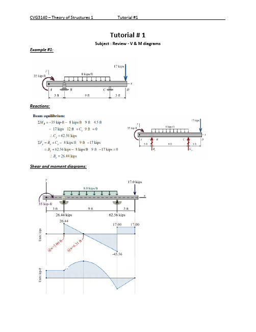
Tutorial # 1
Subject : Review - V & M diagrams Example #1:
Reactions:
Shear and moment diagrams:
CVG3140 – Theory of Structures 1 Example #2:
Area
(A )
i
(h )i
( A)i ∗ (h
)
Alternative: table
i
∫ f ( x) ∗ f
1 0
L
2
( x)dx
1
Example # 4 - Frame Use virtual work to calculate the vertical displacement at point “c” of the frame shown given that EI is given as 1X 10⁵ Kn-m2 .
SI = (3m + r ) -(3j +ec)
m= # of members r = # reactions j= # of frame joints • support = joint • where two or more members meet = joint • free end = joint
- 1、下载文档前请自行甄别文档内容的完整性,平台不提供额外的编辑、内容补充、找答案等附加服务。
- 2、"仅部分预览"的文档,不可在线预览部分如存在完整性等问题,可反馈申请退款(可完整预览的文档不适用该条件!)。
- 3、如文档侵犯您的权益,请联系客服反馈,我们会尽快为您处理(人工客服工作时间:9:00-18:30)。
3 6 2 8 2
so translation unknowns of original structure are 2.
4, Degree of indeterminacy
nn n The degree of indeterminacy (n) is:
n426
5, Primary structure
(a) Standing on the side of deformation, joint 1 can’t rotate (Z1) due to rigid arm; translation (Z2) at joint 2 can’t exit due to link in the primary structure. But , Z1, Z2 are existences in original structure. In order to eliminate the difference, a rotation Z1 and translation Z2 can be enforced at joint 1 and joint 2 respectively in primary structure.
Shearing force —— clockwise is positive about isolating body (free body).
Rotation angle —— clockwise is positive
The following sign is established: Translation —— clockwise rotation of the whole member is positive.
Suppose end B is hinged.
3
M 0 2i(2 AB)
M BA
BAl
F 0
AB
1( 3 AB1 F )
M B 2 A
l 2i BA
The following sign is established: Bending moment —— clockwise is positive relative to end of member; counterclockwise is negative relative to rigid joint or support.
C
C
C
B
D
3、How to decide the number of primary unknowns
(1)、The number of rotation displacements ( n ) is equal to the number of
rigid joints. (2)、The number of translation unknowns ( n ) The method of determining the translation unknowns is as following.
11
2
l
( l 1) 1
11
22 E I 2
3
3E I
1 (1 l 1) 1 1 l
12
21
EI 2
3
6EI
l 1 ( B )
1p E I
l
l 1 ( A )
2p
EI
l
1
(R • C ) (R
AC
1
R
BC
)
2
(1 0 1
l
l
)
AB
Fig.shows a beam, it is fixed at two ends. EI is constant. The beam is subjected
to a force P, rotation at end A is , and rotation at end B is
, the
A
B
translation at end B relative end A is A B , bending moments at end A, B are
desired.
Solution: let solve it using force method.
(1) The primary structure
Ml l l Ml l l F A B 2 2(2B A )
B F A 2 2(2A B )
if original structure is that one end is fixed and the other end is hinged, its
slope-deflection can be deduced .
All rigid joints (including fixed supports) are changed into hinges; calculate degree of freedom of the new structure. The degree of freedom of the new structure is equal to the number of translation unknown of the original structure.
AB
l
2
(R • C )
ABlLeabharlann We havel l
3
E
I
l 1 6EI
B AB
2 EI •l l
A
l
l 6EI
l 1 3EI
A AB
2 EI •l l
B
2EI (2
1
l
A
3 l l l B
AB ) l
2
2
(2
B
)
A
2
2EI l
(2
B
3 l l l A
In the last chapter (force method), the unknowns of primary structure are forces. After obtaining unknown force, displacement of the structure can be solved.
(a) A (b) A (c) A (d) A
q øB
B øB
l
l
øB B
q
øB
B øB
Bq
C Notice: (1) The flexural deformation of the flexural members in the frame is taken into account, but the shearing and axial deformations of which are
AB ) l
2
2
(2
A
)
B
let i E I
l
linear rigidity
We have
3
M 2i(2 AB)
M AB
A
B
l
F AB
M 2i(2
3 AB)
F
M BA
B
A
l
BA
is referred to as “slopedeflection equation”
Solution: (1) It is indeterminate to the second degree (2) Primary Structure:
(3)Canonical equations In order to solve this problem, we must find out the differences between original structure and primary structure at first.
The end moment, end shearing force and end reaction are listed in table for convenience.
Section 4 Analysis of indeterminate Structure using displacement method
Chapter 7 Slope-Deflection Method
Section 1 Introduction
Slope-deflection method (or simply the displacement method) is another method to analyze the statically indeterminate structure.
(2) Canonical equations
1
11 1
12 2
13 3
1p
1
A
2
21 1
22 2
23 3
2p
2
B
Because
M
3
0
11 1
12 2
1p
1
A
21
1
22
2
2p
2
B
Solution:
(3) Determine coefficients (Graph Multiplication)
When indeterminate structure is analyzed by using displacement method, every member is considered as a statically indeterminate beam with single span. So the primary structure is that every member is changed into an indeterminate beam with single span. A rigid arm is added at every rigid joint to prevent rotation of the joint (but can not prevent translation) at the same time, a link is added at joint where translation is possible. The link prevents translation of the joint.