
40GQSFP+光模块介绍
40G QSFP+ AOC
40G QSFP+ AOC应用
高速光互连产品40Gbps QSFP+ AOC 和120Gbps CXP AOC不再采纳传统可插拔收发器中TOSA/ROSA 的结构设计,而使用高度集成的阵列光引擎核心器件技术。实现一体化模式—封装小,速率高, 功耗低(QSFP+功耗低于1.5W,CXP功耗低于2.5W)。在发射端,阵列光学引擎同时处理多个高速 电通道, 将其转换为多路光信号, 再将这些光信号组合在一起, 通过一条12芯(24芯)MPO高密 度光缆将这些信息传送到云计算系统或数据中心机房的下一个节点。在接收端,阵列光学引擎 将MPO光缆内的光信号转换回电信号,将多路电信号传送至设备上处理. 这些产品完全适用 infiniband互联应用场景,同时符合以太网IEEE 802.3ba.在数据中心和云计算系统领域,阵列光 学引擎技术已经广泛应用于有源光缆产品——服务器和交换机之间互联。
MPO与MTP连接头的区别
当今市面上存在MTP和MPO两种光纤连接系统,它们非常相似,在一定程度上能相互兼容。MTP 连接器被描述为高性能的MPO连接器。
MPO (Multi-fiber Pull Off)是日本NTT通信公司设计的第一代弹片卡紧式的多芯光纤连接器,现在 是几家公司生产的一种多芯连接头的名称,这种连接头的插芯有超过1根纤芯,通过机械方式卡 入到位。而MTP,是由美国USConec 公司注册的品牌,专门指其生产的MPO连接器独特的类型。 MTP连接器是一种具有多重创新设计的高性能的MPO连接器,相对于一般的MPO连接器来说, MTP光纤连接器在光学性能和机械性能上都得到了加强。
综上所述,40G SR4 QSFP+光模块适用于短距离的传输,在数据中心中常用来与OM3/OM4带 状光缆一起连接以太网交换机。而40G LR4 QSFP+光模块和40G LR4 PSM光模块则适用于长距离 传输。单就这两个光模块相比较而言,40G LR4 QSFP+光模块更具性价比。因为在长距离的传 输中,40G LR4 QSFP+光模块仅仅只需要两根单模光纤,而40G LR4 PSM光模块需要八根单模光 纤。
QSFP+转4*SFP+高速有源光缆
QSFP+转4*SFP+高速有源光缆产品,一端是40Gbps的QSFP+接口,另一端是4个10Gbps SFP+接口, 中间通过12芯的MPO高密度光缆连接,然后根据客户对于两端线缆长度的需求,在MPO线缆中间 加入分支器,实现一路40G光信号分为四路10G信号。光缆一端采用40G QSFP连接头,符合SFF8436要求;另一端采用4路10G SFP+连接头,符合SFF-8432要求, 是最经济简单的实现交换机端口转换。 传输长度达到1~100米的,对于分支器两端的光缆长度可以自由选择。同理,120G CXP转3个40G QSFP+的互连产品可以解决CXP和QSFP设备互连的问题,需要提出的是中间通过24芯的MPO高密 度光缆扇出3条4芯的产品,完成完美转接。
40G QSFP+ 120G CXP
10G SFP+
40G QSFP原理
40G SR4 QSFP+光模块在40G数据传输中常与MPO/MTP接头一起使用。和40G LR4 QSFP+光模块不 同的是,这种光模块经常用于多模光纤的传输,能支持OM3跳线的100米左右的信号传输和OM4 跳线的150米左右的信号传输。在发送端传输信号时,首先激光器阵列会将电信号转换为光信号, 经过带状多模光纤平行发送。接收端在接收到信号时,光电检测器阵列再将并行光信号转换成 并行电信号。
40G LR4 PSM光模块
40G LR4 PSM光模块主要是根据QSFP+多源协议设计的外观、光/电连接和数字诊断接口。作为 一款高度集成4通道光模块,它拥有更高的端口密度的优势,同时,也为整个系统的运行节省 了不少成本。这种光模块的光口采用了并行单模技术PSM(Parallel Single Mode),利用4路并 行设计的MPO/MTP接口,可实现10,000m的有效传输。40G LR4 PSM光模块的工作原理和 40G SR4 QSFP+光模块的工作原理相同,都是通过激光器阵列将电信号转换为光信号,再由光 电检测器阵列将光信号转换为电信号。不同的是,40G LR4 PSM光模块常用于与单模带状光纤 接头相连,也就是说,并行的光信号是通过8根单模光纤进行平行发送的。
40G QSFP+ LR4工作原理
40G LR4 QSFP+光模块一般与LC接头连接,能支持的单模光纤最大传输距离可达10km。这种光模 块有四个相互独立的发射和接收光信号通道,需使用MUX或DEMUX来对光信号进行复用和解复 用。在接收端,四个传输速率为10Gbps的通道会同时传输。当这些串行数据流被传递到激光驱 动器时,激光驱动器会使用直接调制激光器(Directly Modulated Lasers,DMLs)对波长进行控 制。被直接调制激光器调制过的光信号再经过复用器,被组合在一起在一根单模光纤上进行传 输。快到达接收端时,这些传输的信号再被解复用器被分解成四个传输速率为10Gbps的通道。 然后PIN探测器或互阻放大器对每一个数据流进行恢复,最后蒋光信号传送出去。
40G QSFP+ 光模块
40G QSFP+ 接口规范
QSFP+光模块的两个基本接口规范分别是40GBASE-SR4和40GBASE-LR4。前者用在多模应用中, 后者用在单模应用中。
40G BASE-LR4 QSFP+ 光模块符合802.3ba(40GBASE-LR4)标准,与LC光纤连接器一起使用,传 输速率可达到40Gbps。这种光模块有4个数据传输通道,每个传输通道的传输速率约为 10.3125Gbps,4个通道同时传输数据可实现40Gbps传输。40GBASE-LR4 QSFP+光模块通常用在 数据中心和因特网交换点之间,与单模光纤一起使用,传输距离最高可达10km。
有源光缆AOC--40G QSFP+应用新形式
有源光缆AOC(Active Optical Cable)主动式光纤缆线,也叫做带芯片的光缆。传统的数据中心互联主要是基 于同轴电缆,AOC有源光缆与互联铜缆相比拥有许多显著的优势。比如在系统链路上的传输功率更低,重量 仅为直连铜缆四分之一,体积约为铜缆的一半,并且在机房布线系统中具有更好的空气流动散热性,光缆的 弯折半径比铜缆做得更小,传输距离更远(可以达到100~300米),且产品传输性能的误码率也更优,BER 可以达到10^-15。与光收发模块相比,AOC有源光缆由于存在不外露的光接口,不存在光接口清洁和被污染 的问题,系统稳定性和可靠性大大提升,并且降低机房维护成本。相对于40G DAC铜缆,40G AOC有源光缆 在7米以上的数据传输环境下具备不可比拟的优势,包括体积更小,重量更轻,更容易弯曲,更容易管理, 信号传输距离更长等。 基于光引擎技术的有源光缆产品是实现数据中心高速光互连的最佳解决方案,是一种芯片间的互连结构。目 前市场主流高速光互连AOC产品包括10Gbps SFP+ AOC、40Gbps QSFP+AOC、56G QSFP+AOC 和120Gbps CXP AOC等。
40GBASE-SR4 QSFP+ 光模块符合802.3ba D3.2(40GBASE-SR4)标准,与MPO/MTP光纤连接器 一起使用可实现40Gbps的光学连接。这种光模块也是通过四个通道进行传输,传输速率同 LR4一致。在数据中心,40GBASE-SR4 QSFP+光模块可以和多模OM3/OM4光纤一起使用,达到 100m(OM3)和150m(OM4)的传输,实现两个以太网交换机间的互连。
高速线缆DAC--40G QSFP+应用新形式
QSFP+光模块还可以与QSFP+分支光缆相连,形成一种高密度的解决方案。 根据光缆传输介质的不同,一般又将其分为有源光缆(AOC)和高速线缆(铜质电缆, DAC)。 40G QSFP+ AOC:由一根光纤和两只40G QSFP+光模块相连构成。 40G QSFP+ DAC:由一根铜芯电缆和两只40G QSFP+光模块相连构成,高速线缆传输距离较 短,一般源电缆的最大传输距离在5m左右,而有源电缆传输距离可达15m。目前我司 40G QSFP+ DAC支持最大传输距离为7米,10G SFP+ DAC支持最大传输距离为10米。 DAC 优势:1、由于其采用了光模块和光缆的无缝连接形式,降低了成本的同时确保光口不 外露,减少了灰尘和其他污染物对光缆的影响,提高了传输效率,广泛应用于网络布线中。 2、在材质方面,高速线缆内部由铜芯制成。铜缆具有天然散热器的作用,散热效果好,节 能环保。3、在功耗方面,高速线缆功耗低。由于无源电缆不需要电源,耗电量几乎为0;有 源电缆耗电量一般在440mW左右。跟有源光缆的2W相比,高速线缆在耗能方面具有一定优 势。4、在成本上,铜缆价格远低于光纤,因此,使用高速线缆也会降低整个数据中心的布 线成本。 作为一种40G光模块的低成本替代方案,QSFP+高速线缆已在万兆网卡、万兆交换机、服务 器、超级计算机、云计算、云存储网络等短距高速互联中得到广泛应用。
40G 100G接口、光模块介绍

日期:
密级: 杭州华三通信技术有限公司
以太网带宽的发展历程
虚拟化、数据中心、高性能计算、 视频点播等等技术需求推动以太网 朝着更高、更快的方向快速发展。 2010年6月,IEEE 802.3ba 40G/100G标准
2002年6月,IEEE 802.3ae 10G以太网标准发布
附:什么是MPO连接器
简单来说,MPO连接器就是多合一的转接器,现在主流的是12芯连接器。
LC/SC 一体化
100G:2芯
一体化
*MPO连接器就是多合一的转接器,详细介绍见后。
40G、100G光纤互联说明
传统10G接口常见采用LC接口形式,采用双芯互联。 而40G以太网规范则要求8芯互联,4发4收,建议采用12芯光缆布线解决方案,每 个信道拥有4条专用发射光纤和4条专用接收光纤,中间四条光纤保持闲置。 100G以太网解决方案规定使用24条光纤,分为两个12芯阵列,一个阵列专用于发 射,另一阵列专用于接收。每个阵列中,中间10条光纤用于传输流量,而两端2条光 纤闲置。
Package
CFP QSFP X2 XFP Xenpak SFP/SFP+
Dimension(L*W*H)
144.75×82×13.6 76.4×18.35×8.5 100×36×12 77.95×18.35×8.5 126×36×17 56.5×13.7×8.6
常见光模块封装类型一览
40G 100G 光模块
1998年,IEEE通过了802.3z千兆标准
1995年,IEEE通过了802.3u标准,将以太网的带宽扩大为100Mbps。
1983年IEEE 802.3工作组发布10BASE-5"粗缆"以太网标准,这是最早的以太网标准。
什么是40G QSFP+光模块

一、概念1、40G QSFP+光模块40G QSFP+光模块是传输速率为40Gbps的四通道小型可插拔光模块,可以实现网络设备(如交换机、路由器、媒体转换器等类似设备)与光缆或铜缆之间的互连,其结构比CFP光模块更紧凑,因此更适合端口密度大的应用。
二、分类1、40G QSFP+光模块40G QSFP+光模块比较常见的可分为40GBASE-SR4光模块、40GBASE-LR4光模块、40GBASE-ER4光模块以及40G LR4 PSM光模块。
40G SR4 QSFP+光模块的接口是MPO/MTP,拥有4个独立的全双工通道,常与多模光纤一起使用,与OM3光纤跳线一起使用时的传输距离是100m,与OM4光纤跳线一起使用时的传输距离是150m。
40G LR4 QSFP+光模块的接口是LC双工,具有高密度、高速率、大容量、低成本、低功耗的优势,一般与LC单模光纤跳线一起使用,传输距离最大可达10km。
40G LR4 PSM光模块的接口是MPO/MTP,采用了Parallel Single Mode(并行单模技术,PSM),利用4路并行设计的MPO/MTP接口,传输距离是10km,具有端口密度高、成本低的特点。
40G ER4 QSFP+光模块与40G LR4 QSFP+光模块一样,一般与LC单模光纤一起使用,不同的是,40G ER4 QSFP+光模块将4个10G数据的输入通道转换为4个CWDM光信号通道,每个通道的速率高达11.2Gbps,并将它们多路复用为单通道,用于40G光传输,主要应用于40GBASE-ER4以太网链路、InfinibandQDR和DDR互连、客户端40G电信连接。
三、特点40G QSFP+光模块:1、采用半导体封装技术,内置4个激光器、探测器,可以支持客户高密度单板的需求。
2、需要增加带宽时网络运营商可以在不中断网络服务的情况下增加新的QSFP+光模块。
3、功耗低于3.5W,而旧式CFP模块功耗为8W。
易飞扬40G QSFP+ PSM AOC有源光缆介绍

40G QSFP+ PSM AOC有源光缆产品概要40G QSFP+ PSM AOC有源光缆,光口侧采用了8根单模光纤的PSM(Parallel Single Mode)并行单模技术,利用4路并行设计的MPO/MTP接口,实现了2公里的有效传输。
同时40G QSFP+PSM IR4的模块可以直接和远端的10G SFP+ LR(10GBASE-LR模块相连接。
当数据中心距离传输超过300米的时候,与普通40G QSFP+ LR4相比,40G PSM技术提供低成本的解决方案,让客户灵活方便地拓宽其数据中心的规模。
产品特性✧全双工4频道1310纳米光学平行活跃✧电缆✧传输数据率11.3 gbit / s /通道✧设定触发器- 8436 QSFP +兼容✧热插拔电接口✧微分AC-coupled高速数据接口✧4频道1310海里FP阵列✧4频道PIN光探测器阵列✧最大链接长度的2公里G652单模光纤(SMF)✧最大功耗3.5 w✧住房与连接器✧操作情况下温度0°C + 70°C✧ 3.3 v电源电压✧RoHS 6兼容应用场景✧Infiniband连接特别提款权DDR /日程✧10/40千兆以太网✧2/4/8 Gbps光纤通道✧数据中心和存储阵列描述QSFP PSM AOC是一个高性能、低功耗、长达到互连的解决方案支持40 g以太网光纤通道作为PCIe。
这是符合QSFP对MSA和40 gbe PSM4。
QSFP AOC PSM的组装4全双工通道,其中每个车道能够传输数据atrates 10 gb / s,提供一个聚合的速度40 gb / s。
ModSelL销ModSelL输入销。
低了主机时,模块响应2线串行通信命令。
ModSelL允许使用多个QSFP模块在一个2线接口总线。
当ModSelL“高”,该模块不会回应任何2线接口与主机通信。
ModSelL在模块内部上拉。
ResetL销重置。
LPMode_Reset在模块内部上拉。
40GQSFP+光模块的介绍

40G LR4 PSM光模块
40G LR4 PSM光模块主要是根据QSFP+多源协议设计的外观、光/电连接和数字诊断接口.作为一 款高度集成4通道光模块,它拥有更高的端口密度的优势,同时,也为整个系统的运行节省了不少 成本.这种光模块的光口采用了并行单模技术PSM〔Parallel Single Mode,利用4路并行设计的 MPO/MTP接口,可实现10,000m的有效传输.40G LR4 PSM光模块的工作原理和40G SR4 QSFP+光 模块的工作原理相同,都是通过激光器阵列将电信号转换为光信号,再由光电检测器阵列将光信 号转换为电信号.不同的是,40G LR4 PSM光模块常用于与单模带状光纤接头相连,也就是说,并行 的光信号是通过8根单模光纤进行平行发送的.
MPO与MTP连接头的区别
当今市面上存在MTP和MPO两种光纤连接系统,它们非常相似,在一定程度上能相互兼容.MTP连接 器被描述为高性能的MPO连接器.
MPO <Multi-fiber Pull Off>是日本NTT通信公司设计的第一代弹片卡紧式的多芯光纤连接器,现在是 几家公司生产的一种多芯连接头的名称,这种连接头的插芯有超过1根纤芯,通过机械方式卡入到 位.而MTP,是由美国USConec 公司注册的品牌,专门指其生产的MPO连接器独特的类型.MTP连接器 是一种具有多重创新设计的高性能的MPO连接器,相对于一般的MPO连接器来说,MTP光纤连接器 在光学性能和机械性能上都得到了加强.
Cisco兼容40G QSFP+ 光模块用户指南说明书
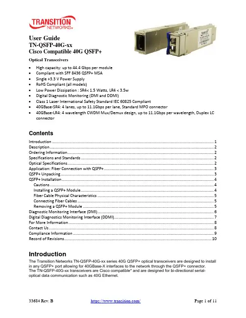
User GuideTN-QSFP-40G-xxCisco Compatible 40G QSFP+Optical Transceivers•High capacity: up to 44.4 Gbps per module•Compliant with SFF 8436 QSFP+ MSA•Single +3.3 V Power Supply•RoHS Compliant (all models)•Low Power Dissipation : SR4< 1.5 Watts, LR4 < 3.5w•Digital Diagnostic Monitoring (DMI and DDMI)•Class 1 Laser International Safety Standard IEC 60825 Compliant•40GBase-SR4: 4 lanes, up to 11.1Gbps per lane, Standard MPO connector•40GBase-LR4: 4 wavelength CWDM Mux/Demux design, up to 11.1Gbps per wavelength, Duplex LC connectorContentsIntroduction (1)Description (2)Ordering Information (2)Specifications and Standards (2)Optical Specifications (2)Application: Fiber Connection with QSFP+ (3)QSFP+ Unpacking (3)QSFP+ Installation (4)Cautions (4)Installing a QSFP+ Module (4)Fiber Cable Physical Characteristics (5)Connecting Fiber Cables (5)Removing a QSFP+ Module (5)Diagnostic Monitoring Interface (DMI) (6)Digital Diagnostics Monitoring Interface (DDMI) (7)For More Information (8)Contact Us (8)Compliance Information (9)Record of Revisions (10)IntroductionThe Transition Networks TN-QSFP-40G-xx series 40G QSFP+ optical transceivers are designed to install in any QSFP+ port allowing for 40GBase-X interfaces to the network through the QSFP+ connector.The TN-QSFP-40G-xx transceivers are Cisco compatible* and are designed for bi-directional serial-optical data communication such as 40G Ethernet.DescriptionTransition Networks’ QSFP+ modules fully comply with the Multi-Sourcing Agreement (MSA).This compliance allows our QSFP+ modules to be used in all other MSA compliant QSFP+ platforms. In addition, TN QSFP+ modules are also compatible with all Cisco QSFP+ based routers and switches, as well as Cisco’s IOS software. TN QSFP+ modules are not Cisco OEM brand modules. Ordering InformationProduct Number DescriptionTN-QSFP-40G-LR4 QSFP+ 40GBase-LR4, 1271nm, 1291nm, 1311nm, 1331nm, single mode (LC)[10km/6.2mi.] Link Budget: 7.0 dBTN-QSFP-40G-SR4 QSFP+ 40GBase-SR4, 850nm multimode (MPO) [400m/1313ft. on OM4, 300m/985ft. on OM3] Link Budget: 2.3 dBTN-QSFP-40G-LR4-3 QSFP+ 40GBase-LR4, 1271nm, 1291nm, 1311nm, 1331nm single mode (LC)[30km/18.7mi.] Link Budget: 9.0 dBSpecifications and StandardsThe TN-QSFP-40G-xx was designed to meet these standards and specifications:Optical SpecificationsThe Optical Specs for all Transition Networks’ SFPs are available on our Optical Devices webpage.Application: Fiber Connection with QSFP+Applications include: 40G Ethernet, 10G Ethernet, and Data Center Aggregation Connection.QSFP+UnpackingBefore you start installing the TN-QSFP-40G-xx, verify that the package contains the following items: o One TN-QSFP-40G-xx SFPo Two protective foam pieceso One Documentation PostcardNotify your sales representative immediately if any of the above items is missing or damaged. Save the packaging for possible future use.The optical ports of the QSFP+ transceiver must be terminated with an optical connector or with a dust plug. The QSFP+ transceiver must be operated within the specified temperature and voltage limits.QSFP+ InstallationCautions•The QSFP+ tranceiver module is keyed to only be installed one way. However, if forced the wrong way, damage may occur. •Avoid getting dust or other contaminants into the fiber bore of the QSFP+ transceiver module. •Clean the optic surfacees of the optical fiber before you plug them back in to the optical bores of another QSFP+ tranceiver module. • Each port must match the wavelength specifications on the other end of the cable, and the cablemust not exceed the specified cable length for reliable communications.Installing a QSFP+ Module1. Attach an ESD-preventive wrist strap to your wrist and to the ESD ground connector or a bare metalsurface on your chassis.2. Remove the QSFP+ transceiver module from its protective packaging. Note: Do not remove theoptical bore dust plugs until directed to do so in a later procedure.3. Check the slot orientation. Note that for some devices (e.g., S4224) some slots are “upside down”compared to other slots.4. Position the QSFP+device at the desired installation slot, with the label facing correctly.5. Carefully slide the QSFP+ device into the slot, aligning it with the internal installation guides.Triangleindicates bottomof SFP cageSFP Module Label side top of SFP moduleBaleClasp SwitchFully Inserted SFPSwitch 6. Ensure that the QSFP+device is firmly seated against the internal mating connector. To verify that theQSFP+ is seated and latched properly. a ) Grasp the QSFP+ by the sides and try to remove it without releasing the latch. b) If the QSFP+ can not be removed, it is installed and seated properly. If the QSFP+ can be removed, reinsert it and press harder with your thumb; repeat if necessary until it is latched securely into the socket.7. Connect the fiber cable to the fiber port connector of the QSFP+ device. Make sure the QSFP+release latch is in the up (closed) position when you insert the cable connector into the QSFP+.8. Remove the dust plug from the connector. Save the dust plug for future use.9. Attach an appropriate cable into the QSFP+ module port.10. Attach the other end of the cable into the other device.11. Observe the status LED(s). See the related manual for details.Fiber Cable Physical CharacteristicsThe fiber cable physical characteristics must meet or exceed IEEE 802.3ae specifications:•Single mode fiber (recommended): 9 μm•Multimode fiber (recommended): 62.5/125 μm•Multimode fiber (optional): 100/140, 85/140, 50/125 μmWarning: Visible and invisible laser radiation when open. DO NOT stare into laser beam or view directly with optical instruments. Failure to observe this warning could result in damage to your eyes or blindness. Connecting Fiber CablesTo install the fiber cable, do the following:1. Locate the appropriate fiber cable.2. Install the cable as shown below.Removing a QSFP+ModuleCaution: Be careful when removing the QSFP+ from a device. Some QSFP+ transceiver module temperatures may exceed 160°F (70°C) and be too hot to touch with bare hands. Note: Do not remove and replace the QSFP+ modules more often than necessary; excessive QSFP+ removing and replacing can shorten the useful life of the QSFP+.1. Attach an ESD-preventive wrist strap to your wrist and to the ESD ground connector or a bare metalsurface on your chassis.2. For future reattachment of fiber-optic cables, note which connector plug is send (TX) and which isreceive (RX).3. Remove the QSFP+ transceiver module:a. If the QSFP+ transceiver module has an actuator button latch, gently press the actuator buttonon the front of the QSFP+ transceiver module until it clicks and the latch mechanism releases the QSFP+ transceiver module from the socket connector. Grasp the actuator button between your thumb and index finger, and carefully pull the QSFP+ transceiver module straight out of the module slot.b. If the QSFP+ transceiver module has a bail clasp latch, pull the latch out and down to eject theQSFP+ transceiver module from the socket connector. If the bail clasp latch is obstructed and you cannot use your index finger to open it, use a small, flat-blade screwdriver or other long, narrow instrument to open the bail clasp latch. Grasp the QSFP+ transceiver module between your thumb and index finger, and carefully remove it from the socket.4. Replace the Dust Plug.5. Place the removed QSFP+ transceiver module in an antistatic bag or other protective package.Diagnostic Monitoring Interface (DMI)The following DMI port screen and explanation table contains brief definitions of the DMI support offered on some QSFP+ transceiver modules. For further information, see the help option on the CPSMM-xxx, SNMP agent, or Transition Networks Focal Point or ION System GUI. Note: This feature is not availableon all devices and may vary between products. See the related manual for more information.DMI Parameter Description DMI Rx PowerMeasured receive optical power in microwatts and in decibels relative to 1mW. DMI Rx PowerAlarmAlarm status of measured receive optical power. DMI Temp Internally measured temperature of transceiver in degrees Celsius and degreesFarenheit.DMI Temp Alarm Alarm status for internally measured temperature of the transceiver.DMI Bias Current Measured transmit bias current in microamperes.DMI Bias Alarm Alarm status for measured transmit bias current for the interface.DMI Tx Power Measured transmit power in microwatts and in decibels relative to 1mW. DMI Tx Power Alarm Alarm status of measured transmit power.Rx Power Intrusion Threshold Tells the converter to stop passing traffic when the receive power drops belowthe new threshold. This feature is sometimes referred to as 'Intrusion Detection,' since tapping into a fiber to intercept traffic leads to a reduction in receive power.This value can be entered in microwatts or in decibels relative to 1mW.TN-QSFP+ distances, TX power, RX power, and link budgets can be found on Transition Netwoks’ website, document “SFP/XFP Fiber and Copper Connectors.” See at https:///. The fiber optic transmitters on this device meet Class I Laser safety requirements per IEC-825/CDRH standards and comply with 21 CFR1040.10 and 21CFR1040.11.WARNING: Visible and invisible laser radiation when open. Do not stare into the beam or view the beam directly with optical instruments. Failure to observe this warning could result in an eye injury or blindness. IMPORTANT: Copper based media ports such as Twisted Pair (TP) Ethernet, USB, RS232, RS422, RS485, DS1, DS3, Video Coax, etc., are intended to be connected to intra-building (inside plant) linksegments that are not subject to lightening transients or power faults. Copper-based media ports such as Twisted Pair (TP) Ethernet, USB, RS232, RS422, RS485, DS1, DS3, Video Coax, etc., are NOT to be connected to inter-building (outside plant) link segments that are subject to lightening transients or power faults.Digital Diagnostics Monitoring Interface (DDMI)DDMI (Digital Diagnostics Monitoring Interface) provides enhanced digital DMI for optical transceivers which allows real time access to device operating parameters.This section contains brief definitions of the DDMI support offered on some QSFP+ transceiver modules. For further information, see the help option or User Guide for the S3290, S4140, S4212, and S4224. Note: This feature is not available on all devices and may vary between products.The Transceiver Information and DDMI Information sections are described below. DDMI ParameterDescription DMIRx Power (uW) Intrusion Threshold; a level for Rx Power on the Fiber port. If the DMI read value falls below the preset value, an intrusion is detected, and a trap is generated. The default is 0 uW. The range is 0 - 65,535 uW. PortThe device’s port number. VendorThe QSFP+ vendor’s name (e.g., Transition ). Part NumberThe QSFP+ vendor Part number provided by the QSFP+ vendor (TN-10GSFP-SR ). Serial NumberThe QSFP+ Vendor Serial number provided by the QSFP+ vendor (e.g., 8672105). RevisionThe QSFP+ vendor Revision level for part number provided by the QSFP+ vendor. Data CodeThe vendor's manufacturing date code (e.g ., 2011-08-09). TranseiverThe Transceiver compatibility (e.g., 1000BASE_SX or 10G ). CurrentThe current value of temperature, voltage, TX bias, TX power, and RX power. High Alarm ThresholdThe high alarm threshold value of temperature, voltage, TX bias, TX power, and RX power. High Warn ThresholdThe high warn threshold value of temperature, voltage, TX bias, TX power, and RX power. Low Warn ThresholdThe low warn threshold value of temperature, voltage, TX bias, TX power, and RX power. Low Alarm Threshold The low alarm threshold value of temperature, voltage, TX bias, TX power,and RX power.For More InformationTechnical information in this document is subject to change without notice. For more information see the TN SFP webpage.40 Gigabit Ethernet ("40GbE" or "40G") Port Types (40GBASE-CR4, 40GBASE-KR4, 40GBASE-SR4, 40GBASE-LR4, 40GBASE-ER4, 40GBASE-FR, 40GBASE-T) ITU standards descriptions include:40GBASE-SR4 ("short range") is a port type for multi-mode fiber and uses 850 nm lasers. Its Physical Coding Sublayer 64b/66b PCS is defined in IEEE 802.3 Clause 82 and its Physical Medium Dependent PMD in Clause 86. It uses four lanes of multi-mode fiber delivering serialized data at a rate of 10.3125 Gbit/s per lane. 40GBASE-SR4 has a reach of 100 m on OM3 and 150m on OM4. There is a longer range variant 40GBASE-eSR4 with a reach of 300 m on OM3 and 400 m on OM4. This extended reach is equivalent to the reach of 10GBASE-SR.40GBASE-LR4 ("long range") is a port type for single-mode fiber and uses 1300 nm lasers. Its Physical Coding Sublayer 64b/66b PCS is defined in IEEE 802.3 Clause 82 and its Physical Medium Dependent PMD in Clause 87. It uses four wavelengths delivering serialized data at a rate of 10.3125 Gbit/s per wavelength.The amendment to IEEE Std 802.3-2008 includes changes to IEEE Std 802.3-2008 and adds Clause 80 through Clause 88, Annex 83A through Annex 83C, Annex 85A, and Annex 86A. This amendment includes IEEE 802.3 Media Access Control (MAC) parameters, Physical Layer specifications, and management parameters for the transfer of IEEE 802.3 format frames at 40 Gb/s and 100 Gb/s.EIA SFF-8436 Rev 4.8 section 5.5 Color Coding and Labeling of QSFP+ Modules: An exposed feature of the QSFP+ Module (a feature or surface extending outside of the bezel) shall be color coded as follows: Beige for 850nm, Blue for 1310nm, and White for 1550nm. For more information seeftp:///sff/SFF-8436.PDF.Contact UsTechnical Support: Technical support is available 24-hours a dayUS and Canada: 1-800-260-1312International: 00-1-952-941-7600Main Officetel: +1.952.941.7600 | toll free: 1.800.526.9267 | fax: 952.941.2322******************** | ************************** | ******************************AddressTransition Networks10900 Red Circle DriveMinnetonka, MN 55343, U.S.A.Compliance InformationClass I Laser ComplianceThis product has been tested and found to comply with the limits for FDA Class I laser for IEC60825,EN60825, and 21CFR1040 specifications.Translated Safety WarningsWarning Class I laser product. Advarsel Laserprodukt av klasse I.Waarschuwing Klasse-I laser produkt. Aviso Produto laser de classe I.Varoitus Luokan I lasertuote. ¡Advertencia! Producto láser Clase I.Attention Produit laser de classe I Varning! Laserprodukt av klass I.Warnung Laserprodukt der Klasse I. Aviso Produto a laser de classe I.Avvertenza Prodotto laser di Classe I. Advarsel Klasse I laserprodukt.FCC RegulationsThis equipment has been tested and found to comply with the limits for a Class A digital device, pursuant to Part 15 of the FCC rules. These limits are designed to provide reasonable protection against harmful interference when the equipment is operated in a commercial environment. This equipment generates, uses and can radiate radio frequency energy and, if not installed and used in accordance with the instruction manual, may cause harmful interference to radio communications.Operation of this equipment in a residential area is likely to cause harmful interference, in which case the user will be required to correct the interference at the user's own expense.Canadian RegulationsThis digital apparatus does not exceed the Class A limits for radio noise for digital apparatus set out on the radio interference regulations of the Canadian Department of Communications.Le présent appareil numérique n'émet pas de bruits radioélectriques dépassant les limites applicables aux appareils numériques de la Class A prescrites dans le Règlement sur le brouillage radioélectrique édicté par le ministère des Communications du Canada.European RegulationsWarningThis is a Class A product. In a domestic environment this product may cause radio interference in which case the user may be required to take adequate measures.Achtung !Dieses ist ein Gerät der Funkstörgrenzwertklasse A. In Wohnbereichen können bei Betrieb dieses Gerätes Rundfunkstörungen auftreten. In diesem Fäll is der Benutzer für Gegenmaßnahmen verantwortlich.Attention !Ceci est un produit de Classe A. Dans un environment domestique, ce produit risque de créer desinterférences radioélectriques, il appartiendra alors à l'utilsateur de prende les measures spécifiquesappropriées.In accordance with European Union Directive 2002/96/EC of the European Parliament and of theCouncil of 27 January 2003, Transition Networks will accept post usage returns of this product for proper disposal. The contact information for this activity can be found in the 'Contact Us' portion of this document.Der Anschluss dieses Gerätes an ein öffentlickes Telekommunikationsnetz in den EGMitgliedstaatenverstösst gegen die jeweligen einzelstaatlichen Gesetze zur Anwendung der Richtlinie 91/263/EWG zur Angleichung der Rechtsvorschriften der Mitgliedstaaten über Telekommunikationsendeinrichtungen einschliesslich der gegenseitigen Anerkennung ihrer Konformität.CAUTION: RJ connectors are NOT INTENDED FOR CONNECTION TO THE PUBLICTELEPHONE NETWORK. Failure to observe this caution could result in damage to the publictelephone network.Der Anschluss dieses Gerätes an ein öffentlickes Telekommunikationsnetz in den EGMitgliedstaatenverstösst gegen die jeweligen einzelstaatlichen Gesetze zur Anwendung der Richtlinie 91/263/EWG zur Angleichung der Rechtsvorschriften der Mitgliedstaaten über Telekommunikationsendeinrichtungen einschliesslich der gegenseitigen Anerkennung ihrer Konformität.Record of RevisionsRev Date NotesA 8/29/16 Initial release.B 9/6/16 Incorporate editorial changes.Trademarks: All trademarks and registered trademarks are the property of their respective owners.Copyright restrictions: © 2016 Transition Networks. All rights reserved. No part of this work may be reproduced or used in any form or by any means - graphic, electronic or mechanical - without written permission from Transition Networks.Transition Networks TN-QSFP-40G-xx User Guide33684 Rev. B https:///Page 11 of 11。
QSFP

H3C华三QSFP模块
QSFP 模块8.1 QSFP光模块8.1.1 外观图图8-1 QSFP光模块外观示意图8.1.2 具体型号及规格QSFP光模块的传输速率为40Gbps,采用MPO连接器。
表8-1 QSFP光模块属性对外型号中心波长(nm)Fiber Mode 光纤直径(m)模式带宽(MHz*km)传输距离接口指标
QSFP模块
8.1 QSFP光模块
8.1.1 外观图
图8-1 QSFP光模块外观示意图
8.1.2 具体型号及规格
QSFP光模块的传输速率为40Gbps,采用MPO连接器。
8.2 QSFP电缆
8.2.1 外观图
图8-2 QSFP电缆外观示意图
1: 插头2: 拉手
8.2.2 具体型号及规格
8.3 QSFP to SFP+电缆
8.3.1 外观图
QSFP to SFP+电缆:一端是1个QSFP模块;另一端分成4个SFP+模块。
QSFP to SFP+电缆外观示意如图8-3所示。
图8-3 QSFP to SFP+电缆示意图
1: QSFP插头2: QSFP拉手
3: SFP+插头4: SFP+拉手
8.3.2 具体型号及规格。
光模块sfp与sfp、xfp、qsfp、qsfp的区别及参数
光模块SFP+与SFP、XFP、QSFP、QSFP+的区别SFP收发器有多种不同的发送和接收类型,用户可以为每个链接选择合适的收发器,以提供基于可用的光纤类型(如多模光纤或单模光纤)能达到的"光学性能"。
可用的光学SFP模块一般分为如下类别:850纳米波长/550米距离的 MMF (SX)、1310纳米波长/10公里距离的 SMF (LX)、1550 纳米波长/40公里距离的XD、80公里距离的ZX、120公里距离的EX或EZX,以及DWDM。
SFP收发器也提供铜缆接口,使得主要为光纤通信设计的主机设备也能够通过UTP网络线缆通信。
也存在波分复用(CWDM)以及单光纤"双向"(1310/1490纳米波长上行/下行)的SFP。
商用SFP收发器能够提供速率达到4.25 G bps。
10 Gbps 收发器的几种封装形式为XFP,以及与SFP封装基本一致的新的变种"SFP+"。
GBIC(Gigabit Interface Converter的缩写),是将千兆位电信号转换为光信号的接口器件。
GBIC设计上可以为热插拔使用。
GBIC是一种符合国际标准的可互换产品。
采用GBIC接口设计的千兆位交换机由于互换灵活,在市场上占有较大的市场份额。
SFP (Small Form-factor Pluggable)可以简单的理解为GBIC的升级版本。
SFP支持SONET、Gigabit Ethernet、光纤通道(Fiber Channel)以及一些其他通信标准。
此标准扩展到了SFP+,能支持10.0 Gbit/s传输速率,包括8 gigabit光纤通道和10GbE。
引入了光纤和铜芯版本的SFP+模块版本,与模块的Xenpak、X2或XFP版本相比,SFP+模块将部分电路留在主板实现,而非模块内实现10G模块经历了从300Pin,XENPAK,X2,XFP的发展,最终实现了用和SFP一样的尺寸传输10G的信号,这就是SFP+。
易飞扬40G 100G QSFP 光模块测试仪器评测
40G/100G QSFP光模块及AOC误码测试评测相信很多设备商和贸易商在订购和进货的时候能立马通过什么来对这些光模块器件进行一些检查和对功能和性能的一些检测,看产品好不好,功能怎么样,心里没有底,不放心等心里暗示,下面介绍一款既方便携带又小巧的光模块测试仪器,确实很方便,我平时就放在包里。
先分享两张图片,确实小巧,大概一本小笔记本的大小。
这款测试仪器的前面板,左边QSFP1是 40G接口,右边的QSFP2接口支持三种速率的。
测试仪器的后面板就是通常见的USB数据线接口,电源线接口和散热口了PS:为了区分不同速率光模块的工作模式,这款仪器在40G模式时灯是不亮的,100G时灯是长亮的,112G时灯是闪烁的,这个在测试时注意看下就OK了。
因为我们的CHECKER的两个端口都支持40G,因此40G AOC/DAC测试时有两种方式,即单台CHECKER模式和双CHECKER模式,下图为单台CHECKER模式测试链接,很方便。
下图是40G AOC误码测试界面,DDM数据和误码信息一目了然,很简洁。
当然我们的设备也支持两台CHECKER 模式40GAOC/DAC测试链接,需要两个GUI界面显示数据,但是操作同样方便。
PS:40G AOC、DAC一端光模块接一台Checker任意端口,另一端光模块接另一台checker任意端口。
关于设备连接与启动下图是设备与PC链接显示图,无需安装驱动程序,仅需一条数据线和电源线,插入待测模块,打开我们为客户提供的客户端,即可实现测试,整个过程过程不到一分钟,操作非常简便,节省您宝贵的时间。
点击客户端(客户端是设备公司的,需要设备公司发个客户端给您),电脑界面显示框如下图总体界面,即模块刚插上去,GUI界面初始化后,左下角显示OK,左上角Type类型有40GQSFP+,100GQSFP28,112GQSFP28,100G QSFP28 A,112GQSFP28 A可选,相当于一台设备可实现多种封装模块的使用,为您省下费用,而且不用带一些列的测试设备,性价比超高同时减轻您的负担。
2019年最新QSFP+封装形式40G光模块的分类和接口类型
2019 年最新QSFP+封装形式40G 光模块的分类和接
口类型
由于,40G 网络在大型的数据中心是十分普遍,而光纤模块是数据中心
交换机互联条件之一,因为QSFP+光模块可以满足高密度、高速率可插拔的
解决方案需求。
接下来易天光通信(etulink)给大家普及有关于QSFP+封装
形式的40G 光模块分类和接口类型。
QSFP+光模块的分类40G QSFP+ SR4 光模块
40G QSFP+ SR4 光模块采用MPO/MTP 光纤连接器,中心传输波长850nm (多模),应用于40G 网络传输,与多模OM3 光纤跳线一起使用时的传输距
离是100m,与OM4 光纤跳线一起使用时的传输距离可达150m。
40G QSFP+ BiDi SR4 光模块
40G QSFP+ BiDi SR4 光模块采用LC 光纤连接器,中心传输波长850nm (多模),应用于40G 网络传输,传输距离是150m。
40G QSFP+ eSR4 光模块
40G QSFP+ eSR4 光模块采用LC 光纤连接器,中心传输波长850nm(多模),应用于40G 网络传输,传输距离是400m。
40G QSFP+ LR4 光模块
40G QSFP+ LR4 光模块采用的是MPO/LC 双工光纤连接器,具有高密度、高速率、大容量、低成本、低功耗的优势,其工作原理是激光驱动器对串行
数据的波长进行调制,复用器将调制过的光信号组合在一起进行传输,快到
达接收端时,这些传输的信号再被解复用器被分解成四个传输速率为10Gbps
的通道,然后PIN 探测器或互阻放大器对数据流进行恢复,再将光信号传送
出去,传输距离为10km。
40G网络应用下的QSFP+光模块 v
QSFP+是IEEE组织为40G网络定义的一种光模块封装类型,它极大地满足了市场对更高密度的高速可插拔解决方案的需求。
现在,40G网络已经在大多数数据中心十分普遍,而光模块是数据中心设备互连必不可少的组件之一,那么关于40G QSFP+光模块,你了解多少?一、40G QSFP+光模块基础知识40G QSFP+光模块符合SCSI、40G以太网、20G/40G Infiniband等多种标准,它有四个数据传输通道,每个通道的传输速率约为10Gbps,四个通道同时传输可以实现40Gbps的传输速率。
这种光模块主要有两种接口:LC 和MTP/MPO(如下图),分别用在单模应用和多模应用。
二、40G QSFP+光模块接口规范为了满足市场高密度、高速插拔解决方案的需求,QSFP+诞生了。
作为最常见的封装形式之一,40GQSFP+光模块在速度和密度上都优于4通道CX4接口。
QSFP+光模块的两个基本接口规范分别是40GBASE-SR4和40GBASE-LR4。
前者用在多模应用中,后者用在单模应用中。
40G BASE-LR4 QSFP+光模块符合802.3ba(40GBASE-LR4)标准,与LC光纤连接器一起使用,传输速率可达到40Gbps。
这种光模块有4个数据传输通道,每个传输通道的传输速率约为10.3125Gbps,4个通道同时传输数据可实现40Gbps传输。
40GBASE-LR4 QSFP+光模块通常用在数据中心和因特网交换点之间,与单模光纤一起使用,传输距离最高可达10km。
40GBASE-SR4QSFP+光模块符合802.3ba D3.2(40GBASE-SR4)标准,与MPO/MTP光纤连接器一起使用可实现40Gbps的光学连接。
这种光模块也是通过四个通道进行传输,传输速率同LR4一致。
在数据中心,40GBASE-SR4 QSFP+光模块可以和多模OM3/OM4光纤一起使用,达到100m(OM3)和150m(OM4)的传输,实现两个以太网交换机间的互连。