TR600 使用说明书
液体传感器数据协同 hunt TROLL 600 快速入门指南说明书
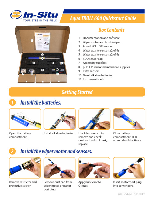
Box Contents1 Documentation and software2 Wiper motor and brush/wiper3 Aqua TROLL 600 sonde4 Water quality sensors (2 of 4)5 Water quality sensors (2 of 4)6 RDO sensor cap7 Accessory supplies8 pH/ORP sensor maintenance supplies 9 Extra sensors10 D-cell alkaline batteries 11 Instrument toolsGetting Started1Install the batteries.2 Install the wiper motor and sensors.Open the battery compartment.Install alkaline batteries.Use Allen wrench to remove and check desiccant color. If pink, replace.Remove restrictor and protective sticker.Remove dust cap from wiper motor or motor port plug.Apply lubricant to O-rings.Insert motor/port plug into center port.Close batterycompartment. LCDscreen should activate.Remove dust cap frompH/ORP sensor.Tighten screw at base ofeach sensor with Allenwrench.Apply a pea-sized drop oflubricant to O-rings.Replace restrictor withvent holes at base ofinstrument.Install sensor in port1. Sensor tongue mustslide into blue interlockgroove.Install remaining sensors. 3Connect the cable to the instrument.Remove protective capsfrom instrument andcable.Ensure O-ring oninstrument connectoris clean. Apply vacuumgrease to O-ring.Flat edge inside cableend must align withflat edge on instrumentconnector.Hold textured sleeve ofcable in one hand andinstrument in other. Pushand twist until click.When using a conductivity sensor and turbidity sensor together, install them side-by-side tomaximize performance.4 Connect the communication device.If desiccant is present, remove it from cable.Align TROLL Com connector with cable end. Push and twist until click.Connect VuSitu directly to instrument. Hold sonde vertically with sensors up. Screen will activate.or5 Connect to the software.Tap the serial number of the instrument or Wireless TROLL Com.VuSitu displays the Connected Instrument screen when pairing is complete.cdLaunch VuSitu and tap Connect .The app locates and displays nearby In-Situ devices.iOS AndroidAn iOS deviceautomatically connects to the closest In-Situ instrument.To connect to another instrument, press Disconnect and then Choose or Add Device . VuSitu displays a list of available connections.aabbYou must have the VuSitu mobile app to use the instrument with a mobile device. Download• Use D-cell alkaline batteries.• Do not use the Aqua TROLL 600 in any manner not specified by the manufacturer.• Do not use batteries of different ages or types.• Do not submerge the Wireless TROLL Com or your mobile device in liquid.• Ensure that sensors, or sensor plugs, are completely inserted into the ports, so that no liquid can enter the instrument.• Ensure that the RDO Sensor Cap is pressed firmly over the sensor lens and is flush with the instrument before submerging in liquid.• Replace the cable if insulation or connectors are damaged.• Make sure the probe and sensor O-rings are clean and free of damage.。
德信 DSA600TRMS 数字钳形电流表 使用说明书

Figure 1IMPORTANT: RECEIVING INSTRUCTIONSVisually inspect all components for shipping damage. If you find damage, notify the carrier at once.Shipping damage is NOT covered by warranty. The carrier is responsible for all repair or replacement costs resulting from damage in shipment.Clamp JawLightInput TerminalPeak Button (PEAK HOLD)HOLD / Backlight /Clamp LightDialFigure 21. FEATURES AND MEASUREMENT FUNCTIONS• 5999 count display• Contoured body provides comfortable single handed grip • Auto ranging• Clamp illuminating LED and backlit LCD to facilitate working in dimly lit situations • Auto shut off feature to extend battery life • Auto shut off disable feature • Low battery indicator • Data hold• Polarity indication: Automatic, + Implied, Negative Polarity Indicator • Over-range indication: ‘0L’ or ‘-0L’• Overload protection• Non-contact voltage detection: 50 to 500 VAC • T emperature measurement: -20°C to 1000°C (-4°F to 1832°F) The K type thermocouple provide (TP-01A) is rated 400°C max.• Resistance measurement: 0.1Ω - 60M Ω• Continuity check: Provides an audible indication above 50Ω• Diode check: Measure the forward voltage drop across a diode junction • Capacitance measurement: 1nF to 1mF • DC voltage measurement: 600 VDC max.• AC voltage measurement: 600 VAC max.• AC current measurement: 600A max.• Frequency measurement: up to 9.999MHz • Duty cycle measurement• Inrush current measurement: First 100ms from being triggered • Relative measurement: Used for comparative measurement• Peak Hold measurement: Captures the + Peak value, - Peak value and Peak to Peak value2. SAFETY WARNINGS• T his instruction manual contains warnings and safety rules which must be observed by the user to ensure safe operation of the instrument and retain it in safe condition.• Read through and understand the instructions contained in this manual before using the instrument.• Keep the manual at hand to enable quick reference whenever necessary.• The instrument is to be used only in its intended applications.• Understand and follow all the safety instructions contained in the manual.• It is essential that all safety instructions are adhered to.• Failure to follow the safety instructions may cause injury, instrument damageappears in the manual.DANGER• Never make measurement on a circuit in which voltage over 600V exists.• Do not exceed the CAT rating of the measuring device • D o not attempt to make measurement in the presence of flammable gases. The use of the instrument may cause sparking, which can lead to an explosion.• T ransformer jaw tips are designed to not short the circuit during a test. If equipment under test has exposed conductive parts extra precaution should be taken to minimize the possibility of shorting.• Never use the instrument if its surface or your hand is wet.• Do not exceed the maximum allowable input of any measuring range.• Never open the battery cover during a measurement.• T he instrument is to be used only in its intended applications or conditions.Use in other than as intended may cause instrument damage or serious personal injury.WARNING• N ever attempt to make any measurement if any abnormal conditions are noted, such as broken case, cracked test leads and exposed metal part.• Do not turn the function selector switch with plugged in test leads connected to the circuit under test.• D o not install substitute parts or make any modification to the instrument. Return the instrument to your distributor for repair or recalibration.• Do not try to replace the batteries if the surface of the instrument is wet.• Always switch off the instrument before opening the battery compartment cover for battery replacement.• Set the Function Switch to an appropriate position before starting measurement.• Firmly insert the test leads.• Disconnect the test leads from the instrument for current measurement.• Do not expose the instrument to the direct sun, high temperature and humidity or dewfall.• B e sure to power off the instrument after use. When the instrument will not be in use for a long period, place it in storage after removing the batteries.• U se only a soft cloth dampened with water or neutral detergent for cleaning the meter. Do not use abrasives, solvents or harsh chemicals. Allow to dry thoroughly before use.Measurement categories (Over-voltage categories)To ensure safe operation of measuring instruments, IEC61010 establishes safety standards for various electrical environments, specified as CAT I through CAT IV, and called measurement categories. Higher-numbered categories correspond to electrical environments with greater momentary energy, so a measuring instrument designed for CAT III environments can endure greater momentary energy than one designed for CAT II.• CAT I: Secondary electrical circuits connected to an AC electrical outlet through a transformer or similar device. • CAT II: Primary electrical circuits of equipment connected to an AC electrical outlet by a power cord. • C AT III: Primary electrical circuits of the equipment connected directly to the distribution panel, and feeders from the distribution panel to outlets. • C AT IV: The circuit from the service drop to the service entrance, and to the power meter and primary over current protection device (distribution panel).CAUTION3 . SPECIFICATION3-1. Measuring range & accuracy(Accuracy guaranteed at 23ºC ± 5ºC, humidity <75%)- Frequency range: 50HzAC CURRENT- I nput voltage range: ≥ 2mV AC (RMS)(Higher frequencies require a larger input voltage)- Input impedance: 10M Ω- Maximum/ input voltage: 250V AC (RMS)- Maximum input voltage: 600V DCDC VOLTAGE- Inrush measurement time: 100ms - Amperage range: 20 ~ 600A - Frequency range: 40 ~ 400HzSURGE CURRENT- Maximum input voltage: 600V AC (RMS)- Frequency range: 40 ~ 1000HzAC VOLTAGEDuty ratio (Clamp Jaws):- F requency response: 10 ~ 1kHz ; - Input current range: ≥20A AC (RMS)- Maximum input current: AC 600A Duty ratio (Test Leads):- F requency response: 10 ~ 10kHz; - Input voltage range: ≥ 60mV AC - I nput impedance: 10M Ω; - Maximum input voltage: 600V AC (RMS)Duty ratio HZ / % : - F requency response: 10 ~ 10MHz; - Input voltage range: ≥ 2V AC (RMS) (Higher frequencies require a larger input voltage)- Maximum /input voltage: 250V AC (RMS)TEMPERATURE MEASUREMENTCAPACITANCERESISTANCE3-3. Accessories• 1 red & 1 black 1000V, 20A test lead• 1 K-type thermocouple (Temperature probe)• 3 AAA batteries • Carrying case4. PREPARATION FOR MEASUREMENT 4-1. Check the condition of the meterDo not use a meter with visible signs of damage. Examine the meter housing before you use the product. Look for cracks, missing plastic or exposed metal. Carefully examine the insulation around the Common and Input terminals.4-2. Check the battery voltageStart with the dial in the “OFF” position then rotate the dial to any position. Confirm that the low battery symbol is not displayed on the LCD screen. If the low battery symbol is displayed follow the instructions in Section 7, Battery Replacement. (It is important to start from the "Off" position to ensure that a blank screen is not due to the auto off feature.)4-3. Check the battery coverThe battery cover must be in place and securely fastened before powering on the meter or connecting test leads to a circuit. See Section 7, Battery Replacement4-4. Check test lead condition, continuity and ratingDo not use damaged test leads. Examine the test leads for worn or cracked insulation. Check test lead continuity. Do not use test leads in applications that exceed their CAT rating. Check the CAT rating of the test lead and refer to Figure 3.4-5. Checking the switch setting & operationConfirm the dial is set to the correct position for the measurement function being performed. Confirm that the symbols displayed on the LED screen match the measurement function. (Refer to Figure 2). Ensure that the Data Hold feature is disabled.5. MEASUREMENT 5-1. Temperature1. Remove the test leads2. C onnect the supplied K-type thermocouple (Temperature probe) to the common and input terminals. Ensure that the red positive (+) side is connected to the input terminal.3. Rotate the dial to the °C °F position4. Contact the sensor (metal part) of K-type temperature probe to the object under test.5. The temperature of the object will be displayed on the LCD screen6. Press the SEL button to toggle between Celsius and Fahrenheit3-2. General Specification• The maximum voltage allowed between terminal and ground: 1000 VDC or 750 VAC • Altitude: Maximum 2000m• Display: 5999 count Backlit LCD • Sampling time: ~ 3 times / sec• Automatic power off: 15 Minutes (Unless disabled)• Power: DC 4.5V• Battery type: (3) 1.5V AAA• Temperature coefficient: <.1 x (specified accuracy) / °C • Operating temperature: 18˚C ~ 28˚C • Storage temperature: -10˚C ~ 50˚C • Size: 2.75” x 8.25” x 1.55”• Weight: ~266 grams (Including batteries, excluding leads)5-3. DC Voltage1. Install the test leads2. Rotate the dial to the position3. Confirm DC V is displayed on the LCD screen4. If DC V is not displayed press the SEL key to toggle between ACV and DCV5. Connect the test leads to the circuit6. The DC voltage will be displayed on the LCD screen5-4. AC Voltage1. Install the test leads2. Rotate the dial to the position3. Confirm AC V is displayed on the LCD screen4. If AC V is not displayed press the SEL key to toggle between DCV and ACV5. Connect the test leads to the circuit6. The AC voltage will be displayed on the LCD screen5-5. AC Current1. Remove the test leads2. Rotate the dial to the 60Ã or 600Ã position3. Press the trigger to open the clamp jaws and place the jaws around a single conductor.4. The current flowing through the conductor will be displayed on the LCD screen5-6. Frequency1. Set up the meter for an AC voltage or current measurement and press the Hz% button2. "Hz" should be displayed on the LCD screen3. Connect the test leads probes to the circuit2. The meter will display the measured frequency on the LCD screen5-7. Duty cycle1. Set up the meter for an AC voltage or current measurement and press the Hz% button2. "Hz" should be displayed on the LCD screen3. Press the Hz% button a second time and "%" should be displayed4. The meter will display the measured duty cycle on the LCD screen5-8. Inrush1. Remove the test leads2. Rotate the dial to the 60Ã or 600Ã position3. Press the INR/REL button for 2 seconds or more4. Confirm "INRUSH" is displayed on the LCD screen5. Turn off the device of which you will be checking the inrush current5-2. Resistance / Continuity / Diode / Capacitance Resistance1. Install the test leads2. Rotate the dial to the position3. Confirm “OL” is displayed on the LCD screen4. S hort the tips of the test leads together and confirm the LCD screen shows near zero5. C onnect the test leads across the device to be tested6. T he resistance of the device will be displayed on the LCD screenContinuity1. Install the test leads2. Rotate the dial to the position3. P ress the SEL button to toggle through the functions until is displayed on the LCD screen4. Confirm “OL” is displayed on the LCD screen5. S hort the tips of the test leads together and the LCD screen should show near zero and the meter should emit a tone6. Connect the test leads across the device to be tested7. A tone will be emitted if the resistance is < 50ΩDiode test1. Install the test leads2. Rotate the dial to the position3. P ress the SEL button to toggle through the functions until is displayed on the LCD screen4. Confirm “OL” is displayed on the LCD screen5. C onnect the test leads probes to the anode and cathode of the diode6. Record the measurement displayed7. R everse the connections and record the measurement displayed(The LCD screen should show ”OL” in one direction and a small forward voltage drop in the other. The forward voltage drop varies. Typical values are .7V for silicon diodes and .3V forgeranium diodes. Please refer to the diode datasheet for specific values. If there is a voltage drop in both directions the diode is shorted. If “OL” is displayed in both directions the diode is open)Capacitance1. Remove the capacitor from the circuit2. Ensure that the capacitor is properly discharged3. Install the test leads4. Rotate the dial to the position5. P ress the SEL button to toggle through the functions until "nF" is displayed on the LCD screen6. C onnect the test leads to the capacitor terminals. (It will take a few seconds for the capacitance to be displayed)6. OTHER FEATURES6.1. Clamp jaw light / Backlit LCD screen1. Rotate the dial to any position other than off2. Press and hold the HOLD button for 2 seconds or more3. The backlit LCD screen will illuminate4. If the meter is on either of the current settings the clamp jaw light will also illuminate5. T he backlit LCD screen and clamp jaw light will remain lit for 15 seconds, or press the HOLD button for 2 seconds to turn them off6.2. Auto shut off / Auto shut of disable1. The meter has an auto shut off feature to preserve battery life2. The meter will shut off after 15 minutes of non-use3. Data hold information will not be retained if the auto off feature is enacted4. I f the meter is turned off by this feature the operator should rotate the dial back to the "OFF" position to resume normal operation5. The auto shut off feature can be disable by holding down the "SEL" key when rotating the dial from the off position6.3. Low battery indicator1. The meter has a low battery indicator that will alert the user when the voltage is too low to provide accurate readings2. Replace the batteries when this indicator is displayed (See Section 7, Battery Replacement)6.4. Data hold1. The meter has a data hold feature that will retain the measured value on the LCD screen.2. Press the HOLD button momentarily to retain the measured value3. The symbol will be displayed while the value is being retained HOLD button again to resume normal operation6.5. Polarity indication1. The meter displays "-" for negative values, positive is implied6.6. Overload indication1. When the input exceeds the measuring range "OL" or "-OL" is displayed on the LCD screen6. P ress the trigger to open the clamp jaws and place the jaws around a single conductor. (Easily accomplished with the use of a line splitter)7. Turn on the device being tested8. The inrush current during the 100ms after start-up will be displayed on the LCD screen 9. Press the INR/REL button again to clear the display 10. Press and hold the INR/REL button to exit the function5.9. Relative measurement1. While taking a measurement press the INR/REL key2. This puts the meter in the relative value measurement mode.3. Pressing the INR/REL key makes the currently displayed value a reference value in memory.4. Subsequent measurements will be displayed as the measured value minus the stored value.5. The meter does not auto range during this function6. The meter will display “OL” if the measurement exceeds the range5-10. Peak Hold1. The Peak Hold function can be used in either the voltage or current settings2. The meter will capture and hold the highest and lowest values measured3. The meter does not auto range during this function4. Follow the first few steps for the measurement type being performed5. Press the Peak/Hold button after the meter is set to take the measurement6. "PMAX" will be displayed on the LCD screen7. Begin taking the measurement7. The highest value measured will be displayed on the LCD screen 8. If "OL" is displayed the range will need to be changed manually 9. T o change the range press and hold the Hz% button for two or more seconds followed by pressing the Peak/Hold button 10. "PMAX" will be displayed on the LCD screen 11. Retake the measurement12. If "OL" is still displayed repeat step 913. O nce the range is set properly the Peak/Hold button can be used to togglethrough PMAX, P MIN and PMAX-MINI peak T1. R otate the dial to the "OFF" position and remove the test leads2. R otate the 1/4 turn fastener CCW with a screwdriver or coin and remove the cover3. Replace the batteries observing correct polarity4. Use new R03 (AAA) or LR03 / 1.5V batteries.5. R einstall the door and rotate the 1/4 turn fastener CW to secure the cover.Replace the batteries when a low battery symbol is displayed on the LCD screen.When the battery is completely exhausted, the display will appear blank and no symbol will be shown.8. MAINTENANCECleaning: U se only a soft cloth dampened with water or neutral detergent for cleaning the meter.Do not use abrasives, solvents or harsh chemicals. Allow to dry thoroughly before use.7. BATTERY REPLACEMENTWARNING• Test on a known live source before use • E ven if the meter does not provide indication, potentially hazardous voltage could still be present (The meter will only detect voltages above 50VAC and only when conditions are correct)• T he meter can be affected by: Distance from voltage source, Condition of meter and batteries, Shielded wires, Metal enclosures, Insulation thickness, Static charge among other things 1. Remove the test leads2. Rotate the dial to the “NCV” position3. Confirm “EF” and “NCV” is indicated on the LCD screen4. Position the tip of the clamp jaws near the voltage source5. A continually cycling tone will be emitted and the clamp light will flash when the meter senses AC voltage greater than ~50V (The meter is sensitive to electrostatic fields. Occasionally a static charge may interfere with the meter detection and the meter may omit a tone momentarily.)6-7. Non-contact Voltage DetectionSPERRY INSTRUMENTS LIMITED LIFETIME WARRANTYSubject to the exclusions and limitations detailed below, Sperry Instruments provides a limited lifetime warranty on productsof its manufacture will be free from defects in materials and workmanship under normal use and service.LimitedLimited means that Sperry Instruments warrants to the original purchasers of products from Sperry Instruments authorized distributors at the time of shipment such products shall be free of defects in material and workmanship while the tool is used under normal working conditions. Standard wear and tear, dulling over time, overloading, misuse, and acts of God are not covered under warranty. This warranty does not cover batteries, fuses, or test leads.When a warranty claim arises, the purchaser must contact Sperry Instruments. If the defect comes under the terms of this limited warranty, Sperry Instruments will arrange, at its sole discretion, one of the following options:• Product will be replacedThe purchaser is solely responsible for determining the suitability of Sperry products for the purchaser’s use or resale, orfor incorporating them into articles or using them in the purchaser’s applications. The distributor is authorized to extend the foregoing limited warranty to its original purchasers in connection with the sales of Sperry products, provided that such products shall not have been altered by the distributor. The distributor shall be fully responsible for any warranties the distributor makes to its purchasers which are broader or more extensive than Sperry’s limited warranty.Lifetime WarrantyWarranty Limitation: The forgoing warranties are exclusive and are in lieu of all other express and implied warranties whatsoever, including but not limited to implied warranties of merchantability and fitness for a particular purpose. The foregoing warranties do not cover ordinary wear and tear, abuse, misuse, overloading, alterations, products which have not been installed, operated or maintained in accordance with Sperry’s written instructions. Test leads, fuses, batteries and calibration are not covered under any implied warranty. “Lifetime” of products that are no longer offered by Sperry will be either repaired or replaced with an item of Sperry Instruments choice of similar value. Lifetime is defined as 5 years after Sperry discontinued manufacturing the product, but the warranty period shall be at least ten years from date of purchase. Original proof of purchase is required to establish original ownership of product.No warranty will be honored unless an invoice or other proof of purchase date is provided to Sperry Instruments. Hand written receipts or invoices will not be honored.©2016 Product Power, LLC All rights reserved.- See more at: /en/resources/warranty-page#sthash.4sNKZu3b.dpufSperry Instruments800-645-5398Menomonee Falls, WI 53051。
Seagate 600 Pro SSD 商品说明书

600 Pro SSD Data SheetA Class Above Client SSDs• Delivers the highest IOPS/watt to improve system performance andreduce power and cooling costs for performance-hungry data centerand cloud applications• Fast, consistent performance and low latency over the warranty periodof the drive• Helps reduce performance gaps between storage I/O and CPU operations• Provides up to 480GB user capacity• Helps safeguard data against unexpected power loss• Helps protect data from undetected, unintentional corruption (silent errors)• One drive—many use casesBest-Fit Applications• Performance-hungry, read-intensive, data center applications, such as dataindexing, edge caching, data streaming, or gaming/software delivery• Cloud system builders, cloud service providers, content delivery networks andvirtualized enterprise environments that demand the highest IOPS/W value• Green IT and TCO reduction initiatives• Power- and space-constrained data centersAMERICAS Seagate Technology LLC 10200 South De Anza Boulevard, Cupertino, California 95014, United States, 408-658-1000 ASIA/PACIFIC Seagate Singapore International Headquarters Pte. Ltd. 7000 Ang Mo Kio Avenue 5, Singapore 569877, 65-6485-3888 EUROPE, MIDDLE EAST AND AFRICA Seagate Technology SAS 16–18, rue du Dôme, 92100 Boulogne-Billancourt, France, 33 1-4186 10 00© 2013 Seagate Technology LLC. All rights reserved. Printed in USA. Seagate, Seagate Technology and the Wave logo are registered trademarks of Seagate Technology LLC in the United States and/or other countries. All other trademarks or registered trademarks are the property of their respective owners. When referring to drive capacity, one gigabyte, or GB, equals one billion bytes and one terabyte, or TB, equals one trillion bytes. Your computer’s operating system may use a different standard of measurement and report a lower capacity. In addition, some of the listed capacity is used for formatting and other functions, and thus will not be available for data storage. Actual data rates may vary depending on operating environment and other factors. Seagate reserves the right to change, without notice, product offerings or specifications.DS1790.3-1310US, October 20131 One gigabyte, or GB, equals one billion bytes when referring to drive capacity.2 Per the JEDEC JESD218A standard using enterprise workload JESD219A with all LBAs allocated.3 Warranty period is either 5 years or when the device life indicator has shown that the device has exhausted its useful life, as defined in the product manual, whichever comes first.4 The drive physical dimensions conform to the Small Form Factor Standard (SFF-8201) found at . For connector-related dimensions, see SFF-8223.600 Pro SSDBeyond a client SSD, the Seagate ® 600 Pro SSD drive leverages proven enterprise expertise, an enterprise-tuned feature set and manufacturing excellence to deliver high levels of data integrity, manageability, interoperability and support. Optimized for NAND technology, Seagate multi-layered error recovery technology with advanced errordetection and correction encoding helps ensure data integrity. Seagate conducts extensive, rigorous failure condition and interoperability testing to deliver the quality and interoperability expected of a true enterprise-class SSD. And of course, this drive is backed by industry-leading support, deep supply chain relationships and global partner networks.。
TR系列力传感器说明书
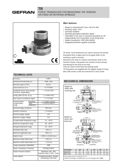
VPT02A10-6PT2 CONNECTOR
N° 4 M6 case screws to prevent the bearing support from rotating.
Direction of the axis of max. sensitivity of the load cell (Indicated by a red dot on the bearing support).
MECHANICAL DIMENSIONS
Model for rollers with revolving hub.
3
Neoprene Sleeve
FLA705 Std Flange
4 seats for M6 fixing screws of the cover
Model for rollers with fixed hub.
0,50%
Nominal full scale load (Ln)
100N...2kN
Nominal output at FSO
2mV/V
Output tolerance at Ln
<± 1% FSO
Combined errors: Non linearity Histeresis, Repeatibility
4 SEATS FOR M6 FIXING SCREW OF THE SUPPORT
CALCULATION OF RESULTANT APPLIED TO CELL
F = Resultant
T = Tension in laminate
P = Roll weight
The red point on the bearing support identifies the axis of maximum cell sensitivity and therefore the direction that F has to take with respect to the transducer.
全站仪 T-600说明书

引言感谢您购买 Johanna T-600系列全站仪。
为了更好地使用仪器,请仔细阅读本说明书,并妥善保管以便日后查阅。
安全使用注意事项:●若擅自拆卸或修理仪器,会有火灾、电击或损坏物体的危险。
拆卸和修理只有本公司和授权的代理商才能进行。
●会引起对眼睛的伤害或变盲。
不要用仪器的望远镜看太阳。
●激光束可能是危险的,使用不正确可能会对眼睛有伤害。
不要自己试图维修仪器。
(仅对应激光下对点仪器)●会引起对眼睛的伤害或变盲。
不要长时间盯看激光束。
(仅对应激光下对点仪器)●高温可能引起火灾。
不要在充电时将充电器盖住。
●火灾或电击的危险。
不要使用坏的电源电缆、插头和插座。
●火灾或电击的危险。
不要使用湿的电池或充电器●可能会发生爆炸。
不要将仪器靠近燃烧的气体、液体使用,不要在煤矿中使 仪器。
●电池可能会引起爆炸或伤害。
不要将电池放在火中或高温环境中。
●火灾或电击的危险。
不要使用非厂方指定的充电器。
●火灾的危险。
不要使用非厂方指定的电源电缆。
●电池短路可能会引起火灾。
存放电池时避免短路。
常规注意事项:在使用本仪器之前,务必检查并确认该仪器各项功能运行正常。
不要将仪器直接对准太阳将仪器直接对准太阳会严重伤害眼睛。
若仪器的物镜直接对准太阳,也会损坏仪器。
将仪器架设到脚架上在架设仪器时,若有可能,请使用木脚架。
使用金属脚架时可能引起的震动会影响测量精度。
安装基座若基座安装不正确,也会影响测量精度。
请经常检查基座上的调节螺旋,并确保基座联结照准部的螺杆是锁紧的。
基座上的中心固定螺旋旋紧。
使仪器免受震动当搬运仪器时,应进行适当保护,使震动对仪器造成的影响最小。
提仪器要点当提仪器时,请务必抓紧仪器的把手。
高温环境不要将仪器放在高温环境中的时间过长,否则会影响仪器的性能。
温度突变仪器或棱镜的温度突变会引起测程的缩短,如将仪器从热的汽车中取出,这时应将仪器放置一段时间使之适应环境温度,再开始测量。
电池检查在作业前请确认电池中所剩容量取出电池建议当处于仪器开机状态时不要取下电池。
TVR6000中文手册

1. 配件................................................................................................................3 MODEL TVR6000 主機配件. .......................................................................3 選購 MODEL AMP-MB/RG1 TRR 測試小機之所增配件. ..........................3
說明:.......................................................................................................... 34 應備工具 :...................................................................................................35 注意事項 :...................................................................................................35 校驗程序 :...................................................................................................35 AD/DA 校正.........................................................................................................36 D/A/ A/D 校正共分為二個步驟 : ..............................................................36
600系列说明书

600系列三相电力仪表(版本号:4.00)使用说明书(使用前请详细阅读此说明书)目录1、简述 (1)1.1 600的功能 (1)1.2 600功能描述 (1)1.3 600的特点 (1)2、安装、接线与配置 (2)2.1 尺寸与安装 (2)2.2 接线与配置 (3)3、界面显示说明 (5)3.1 显示模式下按键功能示意图 (5)3.2 编程模式下参数查询及修改按键功能示意图 (5)3.3 显示模式下功能显示灯指示说明 (6)4、操作说明 (6)4.1 循环显示说明 (6)4.2 键盘编程说明 (6)4.3 功能设置 (6)5、运输与贮藏 (7)6、保修期限及订货说明 (7)附表:常见故障排除 (8)1、简述1.1 600系列的功能600系列三相电力仪表是用于低压电力系统的智能化装置,该系列产品包括电流表、电压表、有功功率表、无功功率表、功率因数表、电度表等适合用户不同应用需求的仪表产品,该系列仪表可以完全替各种代指针式电力仪表,且精确度更好、性能更加稳定。
600系列三相电力仪表具有选配4路开关量输入、2路脉冲输出、RS485通讯接口,通讯协议为MODBUS通讯协议或其它指定通讯协议。
1.2 600系列功能描述1.2.2 通讯功能(扩展功能)600系列产品均可选配RS485通讯接口,通讯协议为MODBUS通讯协议或其它指定通讯协议。
可通过通讯口,可查询全部的测量监控信息。
面板带有带有LED指示灯,用于通讯收/发指示。
1.2.3 1~4路开关量输入功能(扩展功能)600系列产品均可选配1~4路开关量输入,为无源节点输入。
可在测量显示区查看开关量的状态。
1.2.4 模拟量输出功能(扩展功能)600系列部分产品可选配1~2路DC4~20mA,通过编程设置可将模拟量(DC 4-20mA)输出设置为与某一被测参数(定货时需指定)成比例的输出。
模拟量输出的最大负载为300Ω,可选择项为三相电流表的IA、IB、IC,三相电压表的UA、UB、UC。
做无死角女神卡西欧TR600自拍神器试用

做无死角女神卡西欧TR600自拍神器试用卡西欧TR系列的相机早就在广大爱美的年轻女孩子中间有着“自拍神器”的美称,我早年自用过TR150。
最近新出的TR600系列又掀起了一阵风潮。
下面就来感受一下新一代神器的不一般之处吧:新一代的自拍神器设计师依然保留了TR系列经典的外框设计,LCD液晶屏幕可实现多角度翻转取景。
这款自拍神器和苹果iPhone 6s手机差不多大小,对于各位女性用户出门来说,不会带来什么累赘,可以轻松地放在随身的包包中。
卡西欧TR600和iPhone 6s大小相当卡西欧为广大的用户设计了宝石粉、火彩金和欧泊白这三种配色,而我这次拿到的为宝石粉配色版本,相机摄像头部位采用几何线条切割的设计,拿在手中有着不一样的时尚感。
卡西欧TR600在摄像头方面有着4倍变焦的新设计,F2.8的大光圈和21mm的广角等效焦距。
在这样的参数下,人像拍摄可以达到柔美的背景虚化,自拍效果比单纯手机自拍提升了好几个档次。
卡西欧TR600相机正面卡西欧TR600相机背面卡西欧TR600相机闭合状态根据官网参数,卡西欧TR600的机内存储空间为49.9M,最高画质下只能存储不到10张照片,建议用户刚拿到新机器外出拍照时,一定要记得提前插好TF存储卡。
相机右侧有一个OPEN的按钮,轻按然后向下滑动后盖,便可以看到TF存储卡的插槽,插入存储卡便不用担心储存容量的问题,就可以愉快地拍照啦。
电池仓及存储卡槽卡西欧TR600自拍时界面效果相机的开关位于相机顶部,打开之后可以看到上面有一个省略号,点击红色的相机图标,有自动、极智模式和Best Shot等模式可以选择,这些模式都与卡西欧TR150等之前的系列大致相同,通常我们使用美颜模式就好了。
在操作方面,卡西欧TR600和前作TR550一样在侧面加入触控式自拍键。
机身一侧两个凸起的原点之间的区域就是触控区。
自拍时,用户双击自拍键将显示PAD图标,表示自拍键操作已启用,再次双击自拍键可禁用自拍键操作。
- 1、下载文档前请自行甄别文档内容的完整性,平台不提供额外的编辑、内容补充、找答案等附加服务。
- 2、"仅部分预览"的文档,不可在线预览部分如存在完整性等问题,可反馈申请退款(可完整预览的文档不适用该条件!)。
- 3、如文档侵犯您的权益,请联系客服反馈,我们会尽快为您处理(人工客服工作时间:9:00-18:30)。
TR600数字式应变电阻传感器变送器使用说明书LONGTEC 珠海市长陆工业自动控制系统有限公司用前须知:u初次使用前,请详细阅读本说明书,现场使用许多疑难问题,在本说明书中将找到答案。
u使用前,请检查称重系统其他部件是否匹配。
u使用本仪表,注意防晒、防雨水、防撞击。
u使用本仪表,请尽可能配备常用安装、检修工具:小型一字螺丝刀,数字式万用表,称重传感器模拟器(mV信号发生器)。
目录用前须知: (1)1概述 (5)1-1简介 (5)1-2有关术语 (5)1-3特点 (5)2技术参数 (6)2-1一般参数 (6)2-2数字部分 (6)2-3模拟部分 (6)3安装 (7)3-1安装注意事项 (7)3-2变送器输入灵敏度 (7)3-3传感器与变送器之连接法 (8)3-4变送器最长可联接的称重信号电缆长度表 (8)3-5称重传感器接线方式 (8)3-6安装尺寸图(单位:MM) (8)4显示面板及按键说明 (9)4-1前面板及打开保护盖示意图 (9)4-2保护盖 (9)4-3接线端子说明 (10)4-4数码显示说明 (10)4-5在称重状态下各功能键的说明 (10)4-6波特率选择说明 (10)4-7ID地址选择说明 (10)5功能设置 (11)5-1参数设定 (11)5-1-1“FUNC”进入设定 (11)5-1-2“F10”零位跟踪时间 (12)5-1-3“F20”动态检测范围 (12)5-1-4“F30”RS232/485通讯输出速率 (12)5-1-5“F40”小数点选择 (13)5-1-6“F50”分度间距 (13)5-1-7“F6 0”最大量程 (13)5-1-8“F70”数字滤波 (14)5-2经由RS232/RS485接口设定功能(配RS232或RS485有此功能) (15)5-2-1零位跟踪范围 (15)5-2-2动态检测范围 (15)5-2-3RS232/RS485通讯输出速率 (15)5-2-4小数点 (15)5-2-5分度间距 (16)5-2-6最大量程 (16)5-2-7数字滤波 (16)6.仪表标定 (16)6-1标定的意义 (16)6-2操作 (17)6-2-1零位标定 (18)6-2-2秤量间距标定 (18)6-2-3标定错误提示 (19)6-3经由RS232/RS485接口标定(配RS232或RS485有此功能) (20)6-3-1 TR600可经由RS232/RS485接口直接调校 (20)7.称重定值比较量设置按键操作: (21)7-1设置参数步骤 (21)7-2经由RS232/RS485设定比较值(配RS232或RS485有此功能) (23)8.通讯参数的设定 (23)8-1通讯格式说明 (23)8-2波特率的设定 (25)8-3通讯ID地址的设定 (25)9.输入/输出 (25)9-1控制输入 (25)9-1-1输入接口(内置) (25)9-1-2输入接口与外接开关的联接 (26)9-1-3输入接口与PLC的联接......................................................................................错误!未定义书签。
9-2输出控制接口(OC门). (26)9-2-1高低限报警控制输出 (26)9-2-2比较条件说明 (26)9-2-2输出接口与外部电路连接示例 (27)9-2-3输出接口与PLC的联接......................................................................................错误!未定义书签。
9-3通讯接口.. (27)9-1-1 单网络通讯接线示意图(一对一方式) (27)9-3-2 多网络通过RS-232相联接的示意图(一主多从方式) (27)9-3-3 多网络通过RS-485相联接的示意图(一主多从方式) (27)9-4模拟输出接口 (28)9-4-1 技术规格 (28)9-4-2引脚说明 (28)9-4-3输出实例 (29)10.附页 (30)10-1标准ASCII码一览表 (30)10-2TR600功能一览表 (30)11 记录 (31)注:本公司保留对此产品进行修改和改进的权力,因此,技术上的改进,恕不另行通知。
1概述1-1简介TR600应变传感器数字变送控制器(以下简称变送器)是一种多用途电子信号转换设备,集显示﹑变送和控制于一体,具有高低限报警输出,串行数字信号输出,模拟信号输出等多种功能,体积小﹑重量轻﹑性能好﹑价格低;适用于各种拉力、压力、张力测量、称重式料位,料斗秤、天车秤、吊秤、拉压力试验机等电阻应变式称重传感器的应用场合。
同时能满足模拟称量传感器的数字化升级,在粮食、轻工、冶金、建材、化工、有色、能源、机械等各行业工业过程称重与测力上广泛应用。
TR600经过严格的电磁兼容性测试,采用SMT生产,体积小,可靠性高。
1-2有关术语分度间距:指变送器显示值变化的单位数。
分度间距数值只能选择数值1、2、5、10﹑20﹑50中的其中一个。
激励电压:指由变送器提供用以驱动电阻应变式传感器的电压。
电阻应变式传感器输出比率:指从电阻应变式传感器输出的信号电压与激励电压的比率,亦称该电阻应变式传感器的输出灵敏度。
最大量程:指为变送器设置(略去小数点后)可显示的最大数值。
变送器分辨率:指变送器可以分辩处理的最小信号。
自重:指能使电阻应变式传感器产生输出电压的承载器本身的重量。
数字传感器:称重传感器直接配有数字处理器,可与上位机或专用仪表采用数字串口进行点对点的操作(设定、标定等)。
1-3特点Ø适用于所有的电阻应变式测力与称重传感器;Ø采用微处理器控制处理,具有高精度数字称重仪特征;Ø内置轻触式按键,可人工按键操作,亦可通过上位机驱动软件操作;Ø选用清晰、稳定的9.6mm 的6位LED 数码管显示;Ø对于重量显示,可选用如下不同的分度间距:1,2,5,10,20或50;Ø超载时,仪表显示“O.L”信息;Ø小数点位置可以根据需要进行设置,最多可设置4位小数;Ø零位自动跟踪;Ø采用Delta-Sigma 方法;Ø内部分辨率为16,000,000;Ø显示数值范围为500至10,0000;Ø采样速度大约为每秒100次;Ø接通电源时,仪表具有自我诊断功能;Ø具有二个定值控制开关输出;Ø具有极强抗电磁辐射能力;Ø采用开关电源,可宽电压工作(18V∽36V DC)Ø15台TR600通过RS232/RS485接口联网使用;Ø标准输出:u RS232或RS485 通讯口;u二个光耦控制输出,(耐压80VDC,300mA);u模拟输出接口,(4-20mA或0-5V可选择);Ø特殊要求软件可订制。
2技术参数2-1一般参数1.电源:直流18V∽36V ;2.消耗功率:≈8瓦;3.工作温度:从-5℃到45℃(23℉到117℉);4.湿度:≤90%相对湿度(无凝结水);5.重量:≈0.5kg;2-2数字部分1.数字显示:9.6mm的6位LED 数码管;2.负数显示:左边的数码管显示符号:“-”;3.超载显示:显示“O.L”;4.显示范围:500~100,000;5.显示分度间距:1,2,5,10,20或50;6.小数点位置:可选择4个不同位置2-3模拟部分1.适用之传感器类型:所有电阻应变式测力与称重传感器;2.传感器输入电压:直流电10V±5%,最大可提供150毫安的电流;3.仪表灵敏度范围:0.5µV/格~200µV/格;4.输入阻抗:DC 500V时,每个端子之间阻抗不能小于100MΩ;5.可调零位电压范围:0.05mV~15.0mV;6.温度系数:≤8ppm/℃7.非线性误差:≤满刻度的0.005%8.采样方法:Delta-sigma 方法9.采样速率:最高每秒100次10.内部分辩率:16,000,00011.最大显示分度数:10,000分度12.比较周期:约每秒100次13.耐压:在输入端(包括共点端、大地、光电耦输出端、模拟输出端),每两个端子之间为直流500伏(1分钟内的耐压)。
在电源输入端(包括共点端、大地、光电耦输出端、模拟输出端),每两个端子之间为交流1500伏(1分钟内的耐压)。
标准配件亦可选择:1.模拟输出:可选0~5V,0~10V,4~20mA2. 数字输出:可以选择RS232或RS4853安装3-1安装注意事项u不要将TR600安装在阳光直晒处,且需避免温度突然变化、振动;u当温度大约为20℃或68℉,且相对湿度约为50%时,仪表处于最佳工作状态;u本产品经过电磁兼容测试,具有高抗干扰能力,但是传感器的模拟输出和RS232/RS485的输入或输出讯号对电子噪音十分敏感,禁止将这些信号线与动力线捆扎在一起,否则仪表可能受到干扰。
同时请将这些信号线远离仪表或其它设备的交流电源。
并尽量缩短信号线或同轴电缆的长度;u称重系统最后的精度由称重传感器的选用、安装、秤体、信号连接、电源等多种因素共同决定,而不是其中一项;u模拟输出采用单独电源提供,其电源公共端不能与其它公共线(或蔽屏线)接到一起,以免短路,损坏仪表,也不能与动力接地线连在一起;u称重传感器屏蔽线必须与信号线/激励线、地线等不能组成回路,否则会造成仪表输入信号不稳。
3-2变送器输入灵敏度变送器输入灵敏度(A)可通过以下公式计算:(传感器在秤满负荷时的输出电压-传感器在秤处于空载时的电压)A= ╳分度间距(d)最大量程对于TR600,A必须大于或等于0.5μV/d.3-3 传感器与变送器之连接法称重传感器的连接方法如下表所示:称重传感器连接方法3-4 变送器最长可联接的称重信号电缆长度表★只作信号变送,联接多传感器时,各传感器应通过接线盒方式把多路称重信号并接成一路称重信号接至变送器,接线盒至变送器的电缆要求必须有金属屏蔽层,见下表:联接350欧姆传感器数量24号线(米) 20号线(米)16号线(米)1 240 600 1200 3 60 180 300 4(最多)40120200★当用作模拟传感器数字化改造时,须每只传感器配一个TR600,将此秤体各个传感器配的TR600通过串行口进上位机或专用仪表进行点对点标定操作。
3-5 称重传感器接线方式上图为四芯线称重传感器接线图上图为六芯线称重传感器接线图引脚端子编号讯号含义 EXC+ SIG+ SHD SIG- EXC-激励电压输出+ 信号输入+ 屏蔽 信号输入- 激励电压输出-3-6 外形图说明(单位:mm )A 向侧视图俯视图安装说明:采用DIN35导轨卡装。