液体点滴速度控制系统设计
液体点滴速度监控系统的设计说明

液体滴落检测与计数摘要输液是医院常用的治疗手段,传统输液过程中存在着输液速度不精确、需要人工监护等弊端。
本文的目标就是设计一种输液监控系统以解决此问题。
本文设计的液体点滴速度监控装置系统,实现了对输液速度的检测与控制,实现了对储液瓶中液面高度的检测报警,并且动态显示输液速度。
使用者可以通过按键设置输液速度,系统将自动对输液速度进行控制。
当输液结束或输液速度发生异常时,使用发光二极管和蜂鸣器进行报警,继而实现对输液瓶的控制。
系统以80C52单片机为核心,实现对输液瓶控制与液体点滴速度的显示和液体点滴速度的键盘控制;通过外围电路检测储液瓶中液面高度和液体点滴速度;通过实现对步进电机控制以实现对储液瓶高低的控制,来实现控制液体点滴速度。
在整体方案设计中,在保证设计系统能达到的题目要求的精度和稳定度的前提下,考虑到系统的轻便性、实用性、可靠性,经济性,对电路系统进行了优化。
关键词:点滴速度;光电传感器;步进电机;单片机目录任务与要求 (5)一、绪论 (5)1.1课题背景 (5)1.2课题研究的目的和意义 (6)1.3课题的思路与主要框图结构 (6)二、方案比较与论证 (7)2.1控制方案的比较 (7)2.2点滴检测方案比较 (7)2.3液位监测方案比较 (7)2.4速度控制方案 (8)2.5电机的选择 (8)三、系统的硬件设计 (9)3.1系统的硬件设计 (9)3.2.1中央处理单元 (9)3.2.2点滴信号检测单元 (10)3.2.3点滴信号的比较、滤波、整形电路 (11)3.2.4液位检测单元 (11)3.2.5检测电路的抗干扰措施 (12)3.2.6声光报警电路 (13)3.2.7步进电机驱动单元(高度调整单元) (14)3.2.8键盘单元 (14)3.2.9数码管显示单元 (16)3.3芯片时钟电路 (17)3.5复位单元 (17)3.6供电单元 (18)四、液体点滴监控系统的软件设计 (19)4.1各模块软件设计 (19)4.1.1主控模块设计 (19)4.1.2点滴速度测量模块设计 (19)4.1.3电机控制算法 (21)4.1.3.1电机控制原理 (21)4.1.3.2点滴速度控制 (21)4.1.5报警模块设计 (23)4.2.2输入键盘模块的设计 (24)4.4.3数码管显示模块的设计 (24)参考文献 (27)附录 (28)液体滴落检测与计数难度系数:1.0一、任务医用吊瓶注射如图所示,需要检测液体滴落速度和数量。
基于单片机的液体点滴速度监控系统的设计
由普通 电机及步进 电机特性比较,本系统中将使用步进 电机。将
判断处理 ,并 控制步 进电机 的转 动及 LCD显示屏 的显示 ,完成 系统 脉 冲信号转变为角位移或线位移的开 环控制元步进 电器件 即步 进电
装置智能控制 的任 务。该速度 控制模块 中主要包含两个 电路,即单片 机。在一般情况下,脉冲信号的频率和脉冲数决定了步进 电机的转 速
关曩 词 :光电传感器 独立式键盘 智能系统
系统硬件组成部分主要有显示系统、速 度检测系统 、速度控制系
液体速率的改变是利用步进电机改变储液瓶的上下来实现 。在本
统等组成,其中各系统又 由系统内部小件组成 。
系统中,液体的速度检测与液体的速度控制是由两部分不 同的系统构
速度检测模块 :在速度检测模块 中,主要依靠光电传感器对光信 成。其中,液体 速率控制系统是相对 简单 的,主要由 STC89C52芯片
节 目单等功 能。多重 审核、主备机 制可 以更好 的提高播 出安全性 。
责迁移服务的管理和执行,日志归档管理 ,策略管理 ,时钟 校时等服务。
(4)字幕子系统:包括三台网络字幕 机,在编辑站点完成字幕素 自动计审服务器 ,负责计审任务的管理分配和执行。MDC服务器 ,管
材 的编辑 ,保存到远程路径 供字幕播 出站点调 用,可以根据正播表编 理 近 线 存 储 。
号的采集处理,并传输至单片机芯片来进行 计数。速度 检测模 块仅仅 和 ULN2003步进 电机驱 动芯片及步进电机组 成,利用步进电机的正
包含了一个简单 电路 ,即点滴速度检测 电路。
反转 使储液瓶高度发生改变,并最 终使得液体速率改变。
速度控 制模 块 :该模块 中 STC89C52芯片对接 收到的数 据进行
基于单片机的输液滴速控制系统设计

流畅输液,用单片机控制滴速
输液是医院中常见的治疗手段之一,而输液滴速的控制对患者的
治疗有着至关重要的作用。
因此,设计一种基于单片机的输液滴速控
制系统就显得尤为重要。
下面,就来介绍一下本系统的设计理念和具
体实现步骤。
首先,我们需要清楚地了解输液滴速的控制原理。
在常见的输液
滴速控制装置中,滴速控制器通过手动调节,从而控制输液滴数和滴速。
但手动调节存在着误差和不方便的问题,因此,我们需要采用自
动控制的方式,利用单片机进行精确的控制。
接着,在硬件设计方面,我们需要选用高精度的流量传感器和电
磁阀,以确保输液精度和可靠性。
同时,我们将采用LCD1602液晶显
示屏来显示当前的滴速和设定的滴速值,使医护人员能够随时掌握输
液情况。
在软件设计方面,我们将采用PID算法来控制滴速。
PID算法是一种经典的控制算法,具有控制精度高、响应速度快等优点。
具体地,
我们将通过流量传感器实时采集流量数据,并通过PID算法进行处理,计算出当前的滴速值与设定的滴速值进行比较,从而控制电磁阀的开
启和关闭,实现准确的滴速控制。
最后,本系统还具有报警功能。
当输液滴速偏差超过设定值范围时,系统会通过声音和液晶屏等方式进行报警,以提示医护人员及时
处理。
综上所述,基于单片机的输液滴速控制系统为临床治疗提供了可靠的仪器设备,具有快速、准确、智能化等优点,进一步提高了医疗的质量和效率。
液体点滴速度控制教学实验装置的设计
液体点滴速度控制教学实验装置的设计◆王 强单片机的教学实验在信息电子专业的教学中占有十分重要的地位,为了使同学们掌握单片机的开发系统的基本知识,本文设计了一个液体点滴速度自动控制的实验装置,该装置能够由人工设定点滴速度,并能根据监测到的点滴速度通过控制算法达到设定速度,而且调整时间较快。
该装置不仅可以很好地应用到教学实验中,并且还可以推广到实际应用中。
点滴速度自动控制装置教学装置一、前言在传统医疗过程中,给病人输液一直采用人工观测和人工调节点滴的速度,点滴的监控受到医务人员责任心和熟练程度的限制,给病人和医疗过程带来一定的安全隐患。
同时,现阶段实践性教学环节有它的薄弱之处,大都处于滞后、分散、针对性不强、系统性不够、综合性不强等低层次循环状态,师生重视程度不够,一方面,造成学生找不到工作,另一方面,某些岗位的高级应用技术人才紧缺。
为此,必须充分重视实践教学环节,充分发挥出实践性教学的最大功效。
其有效措施之一,就是配合一些优秀的实验教学模型,开展设计性、系统性、综合性的实验和实习教学。
对实验教学模型有几点主要要求:(1)系统性;(2)新技术的综合性;(3)设计性;(4)直观性。
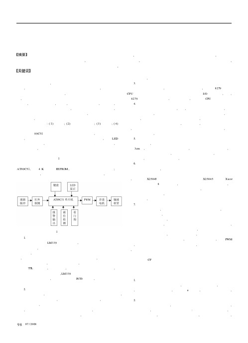
本文将89C51单片机用于对输液实验装置的设计,实现键盘设定输液速度,通过传感系统来确定点滴速度和对液位警戒线的检测,利用LED 数码显示屏实时显示,通过电机控制储液瓶的高度来达到控速的目的,整个系统结构简单,易于实现。
二、硬件设计系统硬件结构框图如图1所示。
主要包括单片机系统、液滴探测、液位检测、报警输出、步进电机控制、看门狗等电路。
单片机系统选用AT89C51,内含4K 字节的EEPRO M ,便于研制阶段反复调试和修改;为提高系统的可靠性,使得当系统掉电、上电后程序可以恢复正常,本文设计了看门狗硬件电路。
图1 系统的整体结构图1.点滴速度检测滴速检测是采用LM339过零比较电路,采用红外发射—接收对管作为液滴检测器件,根据接收到的光强的强弱判断是否有液滴滴下。
毕业设计(论文)-基于单片机的智能化液体点滴速度监测与控制装置设计模板
摘要目前大小医院中所使用的静脉输液器都是悬挂一定高度才能输液,输液速度难以准确限制,这对特护病人和对输液速度有较严格的病人是不方便的。
目前的输液监控报警器笨重、体积大、价格太高,增加医院和病人的费用。
所以如果有液体点滴速度监控装置,必将深受医务人员和病人的欢迎。
因为它有许多的优点,如:可以用按键准确控制速度,可以报警,设备结构简单,费用低等。
所以对液体点滴速度监控的研究十分有意义。
利用单片机设计并制作一个智能化的液体点滴速度监测与控制装置。
该装置由水滴速度测试系统、水速控制系统、显示装置、单片机系统、键盘和报警等系统组成。
应用水的压强随着高度差的变化而变化的原理,利用控制步进电动机的升降来控制点滴速度。
点滴速度可用键盘来设定,设定范围为20~150(滴/分),控制误差范围在10% 1滴左右。
从改变设定值起到点滴速度基本稳定整个过程的调整时间小于3分钟。
同时在水到达警戒线以下时能发出报警信号。
该系统是以单片机89C52为核心,采用了步进电机控制装置、红外光电传感滴速检测装置和通过单片机扫描测量、采用PID控制算法控制直流电机传动装置来实现一个点滴速度自动控制系统。
还扩充了掉点数据存储,实施远距离两线制多机通信、语音报警、系统开机自检、回血报警等功能,增强了系统的实用性。
而且由于采用红外光电传感和电容传感配合单片机及可编程逻辑器件,速递测量和控制精度高。
整体结构设计合理,运行稳定。
主机从机间采用自动检测多路访问协议,很好的解决了多机共用一根通讯线的比特流碰撞问题。
关键字:点滴速度,红外传感,步进电动机,52单片机目录1 单片机89C52概述 (1)1.1 AT89C52单片机 (1)1.1.1 89C52输入/输出引脚简介 (1)1.1.2 89C52的存储器配置 (3)1.1.3 电可擦除可编程只读存储器(E2PROM) (3)2 方案 (4)2.1 方案比较,设计与论证 (4)2.1.1控制方案比较 (4)2.1.2 液滴检测方案比较 (4)2.1.3 点滴速度控制方案 (5)2.1.4 储液液面检测方案 (7)2.1.5 通信方案比较 (7)2.1.6 主从机网络通讯构建方案 (8)3 理论分析 (9)3.1 PID控制算法 (9)4 系统设计 (10)4.1 主站部分 (10)4.1.1 主站键盘和显示部分 (10)4.1.2 电源设计 (12)4.1.3 主站软件流程 (12)4.2 从站部分 (13)4.2.1 点滴检测 (13)4.2.2 点滴速度控制模块 (14)4.2.3 步进电机的驱动 (15)4.2.4 警戒检测 (15)4.2.5 传感及测量电路 (16)4.2.6 数字滤波 (18)4.2.7 掉电数据存储 (18)4.2.8 从站软件流程 (18)4.3 通信部分 (19)4.3.1 主从机网络通讯方案 (20)4.3.2 通信方案的选择和硬件结构 (20)4.3.3 通信报文协议 (21)5 调试 (22)5.1 硬件调试 (22)5.2 软件调试 (22)5.3 软硬综合调试 (22)6 总结 (23)感谢 (24)附录一:参考文献 (25)附录二:程序清单 (26)1 单片机89C52概述本设计主要针对AT89C52单片机芯片来设计的。
液体点滴速度监控系统设计
液体点滴速度监控系统设计摘要:本设计研制了一种液体点滴速度监控系统。
该系统以单片机为核心,可以实现自动检测并显示液体点滴的速度、用键盘设定点滴速度和对异常情况进行声光报警等功能。
采用红外光电传感器检测液位信号,通过硬件滤波和保护装置消除杂散光干扰。
并能通过上位机与下位机之间的串行通信,实现对多台下位机进行远程监控与管理。
该系统工作稳定、操作简便,能有效的解决目前简易液体点滴装置和输液泵之间的空缺,在医疗卫生领域中具有广泛的应用前景。
关键词:点滴速度,单片机,串行通信,步进电机Abstract:The monitoring system for the transfusion was developed with microcontroller unit used as a core. The system realizes auto detection and display of the drip velocity. The drip velocity can be set by keyboard and the abnormal event alarm has achieved. The signal of the liquid level was detected by the infrared photoelectric sensor, and the interference of abnormal light was eliminated by the hardware filter and the protect device. In addition, the remote monitoring and managing of several lower computers was achieved by serial communication. The system is stable in performance and simple in operation. The system has bright application future in medical treatment field.Keywords:Dropping speed, Microcontroller unit, Serial communication, Stepping motor目录1前言 (1)1.1 设计背景 (1)1.2 设计目标 (1)1.3 技术路线 (1)1.4 实施计划 (2)1.5 必备条件 (2)2总体方案设计 (3)2.1 方案比较 (4)2.1.1 滴速检测方案 (4)2.1.2 液位检测方案 (4)2.1.3 滴速控制方案 (4)2.1.4 电机选择方案 (5)2.1.5 点滴速度计算方案 (5)3单元模块设计 (7)3.1 各单元模块功能介绍及电路设计 (7)3.1.1 滴速检测模块设计 (7)3.1.2 液位检测模块设计 (7)3.1.3 电机驱动模块设计 (8)3.1.4 声光报警模块设计 (10)3.1.5 键盘模块设计 (10)3.1.6 显示模块设计 (11)3.1.7 通信模块设计 (12)3.1.8 中央控制模块设计 (13)3.1.9 电源模块设计 (14)3.2 电路参数的计算及元器件的选择 (14)3.2.1 时钟电路 (15)3.2.2 复位电路 (15)3.3 功能器件的介绍 (15)3.3.1 AT89C51介绍 (16)3.3.2 8255A介绍 (18)4软件设计 (24)4.1 软件设计所用工具 (24)4.2 软件结构图 (24)4.3 软件流程框图 (25)4.3.1 上位机软件流程框图 (25)4.3.2 下位机软件流程框图 (26)4.3.3 上、下位机通信软件流程框图 (28)5系统调试 (31)6系统功能、指标参数 (38)6.1 系统能实现的功能 (38)6.2 系统指标参数测试 (38)6.2.1 点滴速度测试 (38)6.2.2 报警功能测试 (39)6.3 系统功能及指标参数分析 (39)7结论 (40)8总结与体会 (42)9谢辞 (43)10参考文献 (44)附1 系统的原理电路图 (45)附2 外文文献翻译-译文 (46)附3 外文文献翻译-原文 (56)1前言随着医院管理系统趋向于电子化、网络化,利用单片机与现代控制技术提高医疗器械的自动化程度成为目前主要应用方向之一。
液体点滴速度监控系统的设计
液体点滴速度监控系统的设计该系统主要由硬件和软件两部分组成。
硬件部分包括传感器、控制器、显示器和报警器;软件部分则负责数据处理和显示。
首先,我们需要选择适合的流速传感器。
传感器可以通过各种方式测量流体的速度,比如利用涡街传感器、超声波传感器或者压力传感器。
根据实际需要以及成本等因素,选择合适的传感器。
在液体点滴管路中添加一个流速传感器,传感器会通过传感器信号转换为电信号,并输入到控制器中进行处理。
控制器会对传感器获得的电信号进行放大、滤波等处理,得到准确的液体流速数据。
为了实现实时监测,监控系统需要进行数据处理和显示。
控制器会将处理好的流速数据传输到计算机或者显示器上,并显示在屏幕上。
同时,系统可以设置不同的报警阈值,当液体的流速超过或者低于设定的范围时,报警器可以发出声音或者进行其他形式的报警,提醒医护人员进行处理。
为了确保系统的准确性和稳定性,我们需要进行校准和稳定性测试。
校准可以通过将已知流速的溶液通过系统,与测量值进行比对来实现。
稳定性测试可以通过长时间的运行和监测,检测系统的稳定性和精度。
设计一个完善的液体点滴速度监控系统还需要考虑以下几个方面:1.系统的可靠性和稳定性:在设计和选择硬件设备时,应注意设备的质量和稳定性。
同时,要保证系统能够长时间稳定运行,以便实时监测液体的流速。
2.软件的易用性:设计一个用户友好的界面和操作系统,使医护人员能够方便地使用和操作该系统。
对于不同的用户,可以提供不同的操作模式和权限。
3.数据的存储和分析:系统应具备将数据存储和分析的功能,以便日后查看和分析。
可以将数据存储在本地或者云端,以便随时调取。
4.系统的可拓展性:系统应具备可拓展的功能,比如可以与其他设备进行数据交互、或者可以设置多个液体点滴的监控等。
综上所述,液体点滴速度监控系统是一种用于监测和保障患者安全的设备。
通过选择合适的硬件和软件,进行适当的校准和测试,可以设计出一个高度可靠和准确的液体点滴速度监控系统。
液体点滴速度监控装置设计报告
液体点滴速度监控装置设计报告一、引言液体点滴在医疗领域中广泛应用,用于输液、给药等目的。
监控液体点滴的速度对于保证患者的安全和治疗的有效性至关重要。
为了满足对液体点滴速度进行实时监控的需求,我们设计了一种液体点滴速度监控装置。
二、设计原理三、装置设计1.液位传感器:液位传感器是用于测量液体液位变化的关键组件。
传感器采用了浮球原理,即将一个浮球固定在导轨上,当液位升高时,浮球被抬升,随着液位降低,浮球被下压。
通过浮球的位置变化,可以得到液体的液位变化情况。
2.电子控制单元:电子控制单元包括微控制器、模数转换器和显示屏。
微控制器用于处理传感器的信号,并计算液体点滴的速度。
模数转换器用于将传感器的模拟信号转换为数字信号,供微控制器处理。
显示屏用于实时显示液体点滴的速度。
3.其他组件和接口:装置还需要其他一些组件和接口来支持工作,如电源、按键开关和数据输出接口。
电源用于为整个装置提供电力,按键开关用于启动和停止液体点滴速度监控功能,数据输出接口用于将监控结果输出给其他设备。
四、工作流程1.用户启动装置,并通过按键开关选择开始监控液体点滴速度。
2.液位传感器感知液位的变化,并将模拟信号传递给模数转换器。
3.模数转换器将模拟信号转换为数字信号,传递给微控制器。
4.微控制器根据液位的变化计算出液体点滴的速度,并将结果显示在显示屏上。
5.用户根据显示屏上的速度信息判断液体点滴是否正常,并根据需要进行调整。
五、性能评估1.准确性:液体点滴速度监控装置应具备高精度的液位测量和速度计算能力,以保证监控结果的准确性。
2.稳定性:装置应具备良好的稳定性,能够在各种环境条件下正常工作,不受外界干扰影响。
3.实时性:装置应能够实时监测液体点滴的速度,并将结果及时显示在显示屏上,以满足临床医疗的需求。
六、结论本设计报告介绍了一种液体点滴速度监控装置的设计原理和工作流程。
该装置通过液位传感器和电子控制单元实现对液体点滴速度的实时监控,并通过显示屏将监控结果显示出来。
- 1、下载文档前请自行甄别文档内容的完整性,平台不提供额外的编辑、内容补充、找答案等附加服务。
- 2、"仅部分预览"的文档,不可在线预览部分如存在完整性等问题,可反馈申请退款(可完整预览的文档不适用该条件!)。
- 3、如文档侵犯您的权益,请联系客服反馈,我们会尽快为您处理(人工客服工作时间:9:00-18:30)。
郑州航空工业管理学院英文翻译2011 届自动化专业 3 班级姓名李贵锋学号 67指导教师王威立二О一五年 4 月 3Design of Realizing the Function of Spot SpeedMonitoring and Control Based on SCM TechnologyCHEN Wu-lin1,YAN Jian-sheng1,HUANG Tian-c AN Ling-hui21Department of Electric Engineering, hen1,WANG Jian-qiang1,TI Ordnance Engineering College, Shijiazhuang 050003, China;Phone :+86 0311E-Mail2Shenzhong middle school , HeBei 053800, ChinaAbstract: With a single-chip microcopy (SCM) as its core and assists with some electrical wires, using the infrared technology and so on, this instrument have realized the function of spot speed monitoring and control. To make the system more useful, we add figure-keyboard to it, with which people can set the function of spot speed by ones wish. Now, based on the communication among the SCM(s), consists of a SCM-internet by which one major module can control several small modules. Monitoring and controlling the function of spot speed is the major utilize of the small modules. Besides, emergency-ring, speed setting up and figure displaying and those shall realize the rest. This system monitors the function of spot speed and setting up emergency-ring line by using the infrared transmission. Its resisting interference is so strong that the monitor-precision shall rise greatly. The advantage rich resources of SCM are exploring completely which make function of the system stronger Key words: SCM; the Infrared Transmission.I. IntroductionIn medical, it requests the speed of a bit of transfusion to control in certain scope. Traditional transfusion installation in transfusion course, accompanying the liquid unceasing decreasing in transfusion bottle and the transfusion’s speed of a bit unceasing reduction, cannot satisfy medical requirement. Thisdesign uses the infrared check installation testing speed of a bit, transformation it to digital signal and inputs SCM. SCM shows it using numberal pipe and at the same time SCM controls walking electrical machine according to design, to make the speed control of a bit in the scope that enactments in advance. To increase systematic practicality, from digital keyboard of SCM, user can communicate according to the network and enactment the drop speed o f set point by one’s need, can realize transfusion a bit of several wards from control system. It can replace transfusion with existing hospital by the liquid speed supervisory and control arrangement of a bit which have the characteristic with simple control and high precision. There is wide market prospect in the aspect of hospital and family tend, having higher society and economic benefits. It just follows as fig 1:II. Hardware designA. SCM brief introduction: SCM is more called as tiny controller definitely, is 20 century middle of 70 decade development getting up a kind of rule modular of integrated circuit that faces control , its characteristic is function strong , volume little ,reliability is high , price cheap. Once it came forth,it was convenient in industrial control, data collection and intelligence melt the fields such as appearance,electromechanical unifinication and home appliances and have gotten extensive application, also have raised automation level and the technical level of these fields maximally. Therefore application and the development of SCM have become high-tech with asignificant program of project field.B. Walk into generator: It is a kind of conductedelement of digital control system. It can change the digital quantitative change of input, is correspondingangular displacement or the displacement of straight line, make digital signals into pulse signals, give firstlypulse signals, motor turns a angle or ongoingone step. Sketch is :① THE speed inspection of a bit design: It ado pts the infrared sensor drop speed of measurement point, project with direct current, circuit is simple , has steady performance. Consideration uses a pair of pipe,lean droplet to fall take off reflection infrared ray will make accept pipe unknown and produce low level signals, but reflection signals is too weak , can not be monitored efficiently.② The speed control: It is fast to set an initial altitude first, and detection drips now. Then, regulate repeatedly, controlling step into the revolution of generator according to the relation between high and drop speed reaching suitable, make droplet satisfy to set drop speed highly.③The high detection of face of blade with alarm: Using infrared detection Technology, realize its warning function. Let infrared transmitting tube with take over pipe just for set up in bottle two side, and set up in the altitude of cordon, because of sensor when having water with sink water receive signals strength difference. Therefore but basis take over the strong weak difference of signals, with comparator handling,can get the greater telecommunications discrepancy that water level arouses in critical line , and judging from whether water level reaches cordon, SCM sends alarm signal’s.III. Software designSoftware design is systematic crucial link. If hardware is "skeleton", software is “muscle and nerve". Software design is mainly with signals and control signal `s outputting, the communication between main station and stations and showing with keyboard’s controlling program.(1) Keyboard with showing is complete modular and the frequency that shows are the things that we will consider, because of havingmeasured the speed of a bit, the frequency that shows can set according to needs completely.(2) The software about the communication between main station and stations: With relapse test and elaborate design, with the isolation technology of chief line us have realized standing for war all functions, can realize efficiently to stand for the control of station. Major stands to dispatch information are contained from station number and sign position, as well as the control data that it wants. Stations are in always to take over state , will want to return to main station information, state changes over to dispatch, data’s dispatching completely is still in to take over state, wait main station control and inquiry. Main station adopts to decide point with tour inspection two ways.(3) Software flow chart is as Fig 3:IV. Experiment Result(1) A bit speed control: Set a speed of a bit, the measure by every time with showing that. At the same time, regulate the high to control the speed of a bit, shows as follows: In table, the data analysis of test can be known ,this system has reached title requirement completely ,also, has highest precision under the condition in the mezzo speed, in the two ends of dropping rapid of controlling scope, the controlling error is also on the small side.(2) Liquid surface inspection to give an alarm test: Measure liquid surface’s altitude give an alarm,under the case of the fast rapid speed, have recordedsome groups of data, is respectively.(3) For system enter the time needed by steady state test, the longest time is 1 minute and 32 seconds, this time is from the lowest end to the highest end, and the regulation time of other condition is smaller than this number. By the time that this system enters steady state, is smaller than the index. It satisfies titlerequirement.V. ConclusionThe system have completed title requirement basically and have realized the control regulation of a bit, can compare accurate regulation to assume random setting value .In systematic design course, it is simple that we make great effort line in line with practical attitude, to make the hardware circuitry simpleness and bring into play the agile of program and let high limit to excavate SCM resource, in order to satisfy problem requirement to keep close to life reality. However, since time is hurriedly and the ability infinity. This system still has the place of many worthwhile improvements, with the expecting of the readers’ criticism and comment.REFERENCES[1] Zhang Hong-run Zhang Ya-fan. SCM principle and application Beijing: Tsinghua University pressed in 2005.[2] Kang Hua-guang technical basic digital partial (the edition of 4th) Beijing: It is higher to educate pressed in2000.[3] Blanco J, et al. Micromachined inertial sensor development at north. Proc. 49th Annual Meeting,Institute of Navigation, 1993;实现基于单片机技术的点速度监控和控制装置的设计陈吴林1,燕建生1,黄天成1,王建强1,田灵慧21电气工程工程部、军械工程学院,中国石家庄050003;电话:+ 86 0311电子邮件2、中国河北省中学053800摘要:以一个单片机(SCM)为核心,并协助一些电线,使用红外技术等做出一个器件,这种器件能够实现点速度的监控和控制。