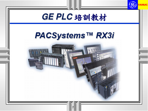
GEPLC第3讲 PACsystem RX3i指令系统1
PAC Systems RX3i介绍

前言在工业化大生产中,随着PLC技术的普及应用,社会上对PLC技术人才的需求明显增加。
可编程序控制器简称PLC,是以微处理器为核心的工业自动控制通用装置。
它具有控制功能强、可靠性高、使用灵活方便、易于扩展、通用性强等一系列优点。
尤其现代的可编程序控制器,其功能已经大大超过了逻辑控制的范围,还包括运动控制、闭环过程控制、数据处理、通信网络等。
它不仅可以取代传统的继电一接触器控制系统,进行复杂的生产过程控制,还可以应用于工厂自动化网络。
目前PLC与CAD/CAM、机器人技术一起并称为当代工业自动化的三大支柱。
因此,PLC应用技术已成为自动化类、机电一体化等专业学生就业时必须掌握的一项技能。
本书从应用的角度出发,以GE-FANUC公司RX3i系列PLC为样机,简单介绍了其指令系统、PLC程序设计的方法与技巧、PLC控制系统的设计和调试等。
本书主要以实例形式介绍了PLC模拟量的处理、人机界面的应用等。
本书在编写时力求由浅入深、通俗易懂、淡化理论、注重应用。
全书共分3章,内容包括:GE-FANUC公司RX3i系列PLC系统特性及硬件构成,RX3i系列系列PLC的编程语言及程序结构,RX3i系列PLC控制系统设计与调试实践和PLC 应用系统设计实例。
本书由南京工程学院郁汉琪担任主编。
参加编写的有南京工程学院许其清、陈巍、王刚、熊新娟、陈兴荣、苏醒、陈国军、陈凯荣、陆欣云、程启华、、史建俊、张志伟、严奎。
由于编者水平有限,书中难免有不足和错漏之处,恳请读者批评指正。
第一篇GE-FANUC简介及基本知识一、基本知识一)硬件介绍——PAC Systems RX3i的特点PAC Systems RX3i控制器是创新的可编程自动化控制器PAC Systems家族中最新增加的部件。
它是中、高端过程和离散控制应用的新一代控制器。
如同家族中的其它产品一样,PAC Systems RX3i的特点是具有单一的控制引擎和通用的编程环境,提供应用程序在多种硬件平台上的可移植性和真正的各种控制选择的交叉渗透。
通用GE PACSystems RX3i系列PLC配置教程

通用GE PACSystems RX3i系列PLC配置教程
PACSystems RX3i系列PLC的编程软件为“Proficy Machine Edition 7.5”。
目的是完成PLC新IP设置,通过网口完成程序下载。
一、已知PLC内设默认IP为192.168.0.100。
二、将编程电脑IP设为与PLC同网段IP,如图1。
图1
再点按钮,可见图2如下。
图2
点上面的按钮,添加100网段IP如图3,填写完毕点,结果如图4。
图3
图4
三、打开PLC程序,将Target内IP和CPU新IP设置如下图5。
图5
四、点击按钮,进行PLC连接,结果如下图6。
图6
五、PLC已连接上,为只读状态,点击变绿的手掌图案按钮,进入可编辑状态,如图7。
图7
六、点击下载按钮,设置如下图8。
图8
七、下载过程中出现如下图9提示,不用理会,点是。
图9
八、图10显示下载成功后的界面。
图10
九、以上下载完成后,PLC会试图与编程电脑连接,如下图11,但由于下载完成后,PLC的IP已经被修改为192.168.100.10,连接会不成功,这是正常的,点Cancel按钮,如下图12,点确定。
图11
图12
十、修改Target中IP如下图13。
图13
十一、重复第四至六步骤后,如下图14,点OK,即完成程序下载。
图14
全文完。
GE Fanuc 自动化 PAC Systems RX3i 系统手册

GE Fanuc 自动化可编程控制器产品PAC Systems RX3i系统手册GFK-2314June 2004杭州集益科技有限公司-您身边的GE PLC专家 0571-********目录第一章产品介绍 ............................................................................................................ 1-1 PACSystems RX3i............................................................................................. 1-2 PACSystems RX3i 性能 ...................................................................... 1-2编程和配置 ................................................................ 1-2从 Series 90-30移植到PACSystems RX3i..................................... 1-2 RX3i Systems模块................................................................................. 1-3 RX3i 模块 (IC695)................................................................................ 1-3RX3i 模块 (IC694)................................................................................ 1-4RX3i 模块 (IC694)................................................................................ 1-5用于 RX3i 系统中的系列90-30 (IC693) 模块 ....................................... 1-6用于 RX3i PAC Systems 的系列 90-30 (IC693) 模块 ................................ 1-7 不能用于R X3i系统中的系列90-30模块........................1-8背板和电源 ..................................................................... 1-10 RX3i Systems的背板........................................................... 1-11RX3i Systems的电源............................................................ 1-11 扩展系统 ......................................................................................... 1-12 使用多个扩展和远程背板.................................1-13 第二章安装 ....................................................................................................... 2-1预安前检测........................................................................................ 2-2系统布局指导 ................................................................................. 2-3 R X3i通用背板尺寸和间距.................................2-5R X3i串行扩展背板尺寸和间距......................2-6 系统配线 ................................................................................................... 2-7 常规配线信息........................................................................ 2-7色标线.................................................................................... 2-7布线安排.............................................................................................. 2-8 系统接地 ............................................................................................. 2-9 接地导体.................................................................................. 2-10背板安全和E M C参考接地...................................2-10电源接地 ......................................................................... 2-11编程器接地 ........................................................................... 2-11屏蔽接地 ..................................................................................... 2-11 系统安装 .......................................................................................... 2-12 通用背板 .............................................................................. 2-12扩展背板............................................................................. 2-14将背板安装在一个19-英寸的机架上 ................................................. 2-16模块 ................................................................................................... 2-18CPU ......................................................................................................... 2-34电源 ........................................................................................ 2-35 GFK-2314 iii杭州集益科技有限公司-您身边的GE PLC专家 0571-********目录串行总线传输模块................................................................. 2-39模块安装................................................................................... 2-39扩展电缆安装 .................................................................... 2-39 第三章背板 ...................................................................................................... 3-1背板种类 ............................................................................................... 3-1RX3i 通用背板: IC695CHS012, IC695CHS016 .............................. 3-2通用背板特性 ................................................................... 3-3通用背板T B1输入端子..................................................3-4Slot 0 ......................................................................................................... 3-4Slot 1到Slot 11 或者15 ................................................................................ 3-5扩展插槽 (Slot 12 或者 16).................................................................... 3-5通用背板上的模块位置...............................................3-6 串行扩展背板: IC694CHS392, IC694CHS398 ........................... 3-7 第四章电源................................................................................................ 4-1电源总览..................................................................................... 4-224 VDC 隔离电源.............................................................................. 4-3RX3i IC695 电源输出 ............................................................ 4-3扩展电源输出 ..............................................................4-4 模块负载要求............................................................................... 4-5电源负载示例 ................................................................ 4-7 用于中性点不接地系统的交流电源连接......................4-8电源, 120/240 VAC 或 125 VDC, 40 Watt: IC695PSA040.................... 4-9指标: IC695PSA040 .................................................................. 4-11发热额定值降级 ................................................................................... 4-12过电流保护 ............................................................................. 4-13现场接线: IC695PSA040 ..................................................................... 4-13 电源, 24 VDC, 40 Watt: IC695PSD040 ............................................. 4-14指标: IC695PSD040 .................................................................. 4-16发热额定值降级 ................................................................................... 4-17过电流保护............................................................................. 4-18现场接线: IC695PSD040 ..................................................................... 4-18 电源, 120/240 VAC或者125 VDC: IC694PWR321............................... 4-19指标: IC694PWR321 ................................................................. 4-20过电流保护............................................................................. 4-20现场接线: IC694PWR321 .................................................................... 4-21 电源, 120/240 VAC 或者 125 VDC 高容量: IC694PWR330........ 4-22指标: IC694PWR330 ................................................................. 4-23过电流保护............................................................................. 4-23现场接线: IC694PWR330 .................................................................... 4-24 电源, 24 VDC高容量: I C694PW R331 ................................... 4-25 iv PACSystems RX3i 系统手册– June 2004 GFK-2314杭州集益科技有限公司-您身边的GE PLC专家 0571-********目录指标: IC694PWR331 ................................................................. 4-26过热额定值降级 ..................................................................................... 4-26过电流保护 ............................................................................. 4-27计算输入功率要求:P W R331 .................................... 4-27现场接线: IC694PWR331 .................................................................... 4-28 第五章串行总线传输模块和扩展电缆....................................5-1串行总线传输模块: IC695LRE001................................................... 5-2 技术指标: LRE001 .............................................................................. 5-3扩展模块安装.................................................................... 5-4关闭独立的扩展背板或者远程背板的电源....................5-4 I/O 总线扩展电缆: IC693CBL300, 301, 302 ,312, 313, 314.................. 5-5 带两个接口的电缆: IC693CBL302 ............................................... 5-5带三个接口的电缆: IC693CBL300, 301, 312, 313, 314 ........... 5-6指标: IC693CBL300, 301, 302, 312, 313, 314 ............................. 5-7自制电缆 .......................................................................................... 5-8扩展或远程背板的端接要求....................5-10 第六章离散输入模块................................................................................... 6-1输入模块, 120 Volt AC, 8 点隔离: IC694MDL230 .............................. 6-2 指标: MDL230 ............................................................................. 6-2现场接线: MDL230 ............................................................................... 6-3 输入模块, 240 Volt AC, 8 点隔离: IC694MDL231 .............................. 6-4 指标: MDL231 ............................................................................. 6-4现场接线: MDL231 ................................................................................ 6-5 输入模块, 120 Volt AC, 16 点: IC694MDL240 ......................................... 6-6 指标: MDL240 ............................................................................. 6-7现场接线: MDL240 ................................................................................ 6-8 输入模块, 24 VAC/ VDC 16 点正/负逻辑: IC694MDL241................. 6-9 指标: MDL241 ............................................................................. 6-9现场接线: MDL241 .............................................................................. 6-10 输入模块, 125 Volt DC正/负, 8 点: IC694MDL632........................... 6-11 指标: MDL632 ........................................................................... 6-12现场接线: MDL632 .............................................................................. 6-13 输入模块, 24 Volt DC正/负, 8 点: IC694MDL634............................. 6-14 指标: MDL634 ........................................................................... 6-14现场接线: MDL634 .............................................................................. 6-15 输入模块, 24 Volt DC正/负, 16 点: IC694MDL645........................... 6-16 指标: MDL645 ........................................................................... 6-16现场接线: MDL645 .............................................................................. 6-17 输入模块: 24 Volt DC 16 点正/负逻辑: IC694MDL646 .................. 6-18 指标: MDL646 ........................................................................... 6-18GFK-2314 目录v杭州集益科技有限公司-您身边的GE PLC专家 0571-********目录现场接线: MDL646 .............................................................................. 6-19 输入模块, 5/12 VDC (TTL) 32 点正/负逻辑: IC694MDL654 .......... 6-20指标: MDL654 ........................................................................... 6-21现场接线: MDL654 .............................................................................. 6-22 输入模块, 24 VDC 正/负逻辑, 32 点: IC694MDL655 ...................... 6-23指标: MDL655 ........................................................................... 6-24现场接线: MDL655 .............................................................................. 6-25 输入模拟器, 8/16 点: IC694ACC300 ...................................................... 6-26指标: ACC300 ........................................................................... 6-26 第七章离散输出模块 ................................................................................ 7-1输出模块, 120 Volt AC, 0.5 Amp, 12 点: IC694MDL310 ....................... 7-2指标: MDL310 ............................................................................. 7-3现场接线: MDL310 ................................................................................ 7-4 输出模块, 120/240 Volt AC, 2 Amp, 8 点: IC694MDL330...................... 7-5指标: MDL330 ............................................................................. 7-6现场接线: MDL330 ................................................................................ 7-7 输出模块, 120 Volt AC, 0.5 Amp, 16 点: IC694MDL340 ....................... 7-8指标: MDL340 ............................................................................. 7-8现场接线: MDL340 ................................................................................ 7-9 输出模块, 120/240 Volt AC 隔离, 2 Amp, 5 点: IC694MDL390 ........... 7-10指标: MDL390 ........................................................................... 7-11现场接线: MDL390 .............................................................................. 7-12 输出模块, 12/24 Volt DC 正逻辑 0.5A 8 点, IC694MDL732 .......... 7-13指标: MDL732 ........................................................................... 7-13现场接线: MDL732 .............................................................................. 7-14 输出模块 125VDC 正/负, 1 Amp, 隔离 6 点: IC694MDL734.......... 7-15指标: MDL734 ........................................................................... 7-15现场接线: MDL734 .............................................................................. 7-16 输出模块, 12/24VDC 正逻辑, 0.5 Amp, 16 点: IC694MDL740 ........... 7-17指标: MDL740 ........................................................................... 7-17现场接线: MDL740 .............................................................................. 7-18 输出模块, 12/24VDC 负逻辑 0.5 Amp, 16 点: IC694MDL741 ............ 7-19指标: MDL741 ........................................................................... 7-19现场接线: MDL741 .............................................................................. 7-20 输出模块, 12/24VDC正逻辑 ESCP, 1A, 16 点: IC694MDL742 .... 7-21电子短路保护............................................................7-21指标: MDL742 ........................................................................... 7-22现场接线: MDL742 .............................................................................. 7-23 输出模块, 5/24 VDC (TTL) 负逻辑, 32 点: IC694MDL752 .......... 7-24指标: MDL752 ........................................................................... 7-25 vi PACSystems RX3i 系统手册– June 2004 GFK-2314杭州集益科技有限公司-您身边的GE PLC专家 0571-********目录现场接线: MDL752 .............................................................................. 7-26典型连接: MDL752 ................................................................. 7-27 输出模块, 12/24VDC, 0.5A 正逻辑, 32 点: IC694MDL753 ............ 7-28 指标: MDL753 ........................................................................... 7-29现场接线: MDL753 .............................................................................. 7-30 输出模块,隔离继电器, N.O., 4 Amp, 8 点: IC694MDL930.............. 7-31 指标: MDL930 ........................................................................... 7-32负载电流限制 .......................................................................... 7-33现场接线: MDL930 .............................................................................. 7-34 输出模块,隔离继电器, N.C. 和 Form C型, 8A , 8 点: IC694MDL931 .... 7-35 指标: MDL931 ........................................................................... 7-36现场接线: MDL931 .............................................................................. 7-37MDL931的负载电流限制....................................................... 7-38 输出模块, 继电器输出, N.O., 2 Amp, 16 点: IC694MDL940 ............. 7-39 指标: MDL940 ........................................................................... 7-40负载电流限制: MDL940........................................................... 7-41现场接线: MDL940 .............................................................................. 7-42 第八章离散混合模块 .................................................................................... 8-1高速计数器模块: IC694APU300 ..................................................... 8-2 指标: APU300.............................................................................. 8-3现场接线: APU300................................................................................. 8-4 第九章模拟量输入模块 ..................................................................................... 9-1模拟量输入处理...................................................................................... 9-2 差分输入 ....................................................................................... 9-2 模拟量输入模块,4通道差分电压:I C694A L G220................. 9-3 指标: ALG220.............................................................................. 9-4数据格式: ALG220 ................................................................................ 9-5现场接线: ALG220 ................................................................................. 9-6 模拟量输入模块,4通道差分电流:I C694A L G221 ................. 9-7 LEDs.......................................................................................................... 9-7指标: ALG221.............................................................................. 9-8数据格式: ALG221 ................................................................................ 9-9现场接线: ALG221 ............................................................................... 9-10 模拟量输入模块, 16 / 8 通道电压: IC694ALG222.......................... 9-11 LEDs........................................................................................................ 9-11指标: ALG222........................................................................... 9-12配置: ALG222 ............................................................................ 9-13数据格式: ALG222 .............................................................................. 9-14现场接线: ALG222 ............................................................................... 9-16 模拟量输入模块, 16 通道电流: IC694ALG223.............................. 9-17GFK-2314 目录vii杭州集益科技有限公司-您身边的GE PLC专家 0571-********目录模块电源 .......................................................................................... 9-17LEDs........................................................................................................ 9-17指标: ALG223............................................................................ 9-18配置: ALG223 ............................................................................ 9-19数据格式: ALG223 .............................................................................. 9-20现场接线: ALG223 ............................................................................... 9-22 第十章模拟量输出模块 ................................................................................ 10-1模拟量输出模块, 2 通道电压: IC694ALG390............................... 10-2LED.......................................................................................................... 10-2指标: ALG390............................................................................ 10-3数据格式: ALG390 .............................................................................. 10-4现场接线: ALG390 ............................................................................... 10-5 模拟量输出模块, 电流, 2 通道: IC694ALG391 ............................. 10-6LED.......................................................................................................... 10-6指标: ALG391............................................................................ 10-7负载电流降级 ............................................................................. 10-7数据格式: ALG391 .............................................................................. 10-8现场接线: ALG391 ............................................................................... 10-9 模拟量输出模块,电流/电压, 8 通道:I C694ALG392 .............. 10-11LEDs...................................................................................................... 10-11指标: ALG392.......................................................................... 10-12额定降低曲线: ALG392 ...................................................................... 10-13电流和电压范围和分辨率 .........................................10-15模块数据 .......................................................................................... 10-16现场接线: ALG392 ............................................................................. 10-17配置: ALG392 .......................................................................... 10-18 第十一章模拟量混合模块 .................................................................................... 11-1模拟量模块, 4 输入/2 输出, 电流/电压型: IC694ALG442............... 11-2模块特性 ...................................................................................... 11-2隔离的 +24 VDC 电源.......................................................................... 11-2LEDs........................................................................................................ 11-2指标: ALG442............................................................................ 11-3现场接线: ALG442 ............................................................................... 11-5输入缩放比例 ............................................................................................ 11-6I/O 数据: ALG442 .................................................................................... 11-8状态数据: ALG222 ............................................................................... 11-9配置: ALG442 .......................................................................... 11-10ALG442的斜坡模式处理....................................................... 11-11根据需求转换模块处理............................................11-13 viii PACSystems RX3i 系统手册 – June 2004 GFK-2314杭州集益科技有限公司-您身边的GE PLC专家 0571-********目录第十二章特殊模块 ............................................................................. 12-1以太网接口模块: IC695ETM001 ....................................................... 12-2 指标: IC695ETM001 .................................................................. 12-3以太网接口 ........................................................................... 12-3站管理器 ...................................................................................... 12-4固件升级 ................................................................................. 12-4以太网全局数据 (EGD) .................................................................... 12-4 以太网接口的控制和指示器....................................................... 12-5 LEDs........................................................................................................ 12-5以太网重启动按钮 .................................................................... 12-5连接器 .............................................................................................. 12-5 运动控制模块: IC694DSM314 ............................................................... 12-6 总览.................................................................................................. 12-7特性: DSM314 ................................................................................... 12-8屏蔽接地连接 ....................................................................... 12-8 附录 A 产品认证和遵循的安装指导.........A-1 RX3i 机构认证 .....................................................................................A-1UL Class 1 Division 2 危险区域必须条件 .................................A-2AT EX Cl a s s 1 Z o n e 2危险区域必须条件.................................A-2标准总揽..........................................................................................A-3 P A C S y s t e m s R X3i环境指标.......................................A-3附加的 RX3i 技术指标....................................................................A-3技术指标 Group 1 ...............................................................................A-4技术指标 Group 2 ...............................................................................A-5 政府规定...................................................................................A-6和标准一致的安装向导.......................................A-7 安装金属外壳的要求.....................................A-8 屏蔽电缆替代金属管道选择...............................................................A-9 通信电缆 ..............................................................................A-9I/O 电缆..................................................................................................A-9模拟/高速计数器电缆 ........................................................................A-9控制柜供电(I C694电源)..............................A-10屏蔽终端 ...................................................................................A-11专业的屏蔽电缆供货商 ...........................................................A-11 欧洲地区有关安全的安装指导....................A-12GFK-2314 目录ix杭州集益科技有限公司-您身边的GE PLC专家 0571-******** Contents附录 B 32-点模块的I/O电缆 .................................................................... B-1预制I/O电缆:I C693C B L327/328和IC693CBL329/330/331/332/333/334..................................................................B-2连接器深度........................................................................................B-3 32-点模块的接线端子块: IC693ACC337.........................................B-4自制长度的 24–针连接器电缆制作 ............................................B-5自制电缆的连接器深度..................................................B-6 附录 C 散热计算 .........................................................................C-1模块散热 ........................................................................... C-1电源散热 .................................................................C-1离散输出模块散热...........................................C-2离散输入模块散热..............................................C-3总散热 ............................................................................... C-4 附录 D 电缆屏蔽层箝位组件................................................................. D-1安装电缆夹子组件...............................................................D-2电缆直径 ......................................................................................... D-2剥去绝缘外壳 ................................................................. D-3典型安装.................................................................................... D-3 x PACSystems RX3i 系统手册– June 2004 GFK-2314产品介绍本章节将对 PACSystems™ RX3i 产品和其特性进行概括性的介绍。
GEPLCPACSystems培训教材
Multipurpose Power Supply
Multipurpose Power Supply Configured for Redundancy
18
Backplane Wattage Available
40 watts
80 Watts
120 Watts
160 watts
40 Watts and redundant supply
記憶體 (Word)
10M
I/O 本地 AI/O
I/O 遠程
2624 1312 32K DI 32K DO 32K AI 32K AO
掃描時間
0.23 ms/K
通訊
RS485 (內建) RS232 (內建) Ethernet Modbus Genius DeviceNet
可 Redundant
IC695CMU310
送電及內部處理
輸入掃描 程序掃描 輸出掃描
診斷及除錯處理
5
PLC 控制系統的基本工作原理(2)
程式掃描: CPU從第一條用 戶程式開始, 根據輸入映像 表, 及其他數據狀態來確定 對外部設備的控制, 將控制 訊息送到輸出映像表.
送電及內部處理
輸入掃描 程序掃描 輸出掃描
輸出掃描: 將輸出映像表的 狀態傳送到輸出模塊, 開設 下一個掃描週期.
Multipurpose Power Supply
Multipurpose Power Supply
Multipurpose Power Supply Configured for Redundancy
Multipurpose Power Supply Configured for Redundancy
GE智能平台PACSystemsRX3i系统在油库站控系统中的应用

GE智能平台PACSystemsRX3i系统在油库站控系统中的应用摘要:本文通过对大庆南三油库站控系统的介绍,向读者描述了GEIP智能平台PAC3i系统在油库站控系统中成功应用的一套完整解决方案。
关键字:GE智能平台 PACSystems RX3i 站控系统油库应用背景:位于黑龙江省大庆市林源的南三油库隶属于中国石油天然气集团公司,是大庆油田的原油储备库和中转枢纽。
同时,南三油库也是我国从陆路进口俄罗斯原油的重要战略储备库,2004年至今南三油库已累计接卸俄油3000余万吨。
坐落在南三油库的生产运行库是为提高油库原油集中输送与储运能力而修建的大型储运工程,主要发挥将南一油库和北油库的原油集中存储并择机向下游林源泵站外输,并最终外运的功能。
解决方案南三油库的主要作用是完成大庆油田原油和俄罗斯进口原油的收、发、输转和储存任务。
油库的站控系统则是使整个油库储运系统的各个环节有机结合起来,并保证各个环节正常运转,以达到及时、保质、保量、安全地完成原油的收、发、输转和储存任务。
为此,南三油库站控系统需要一套可靠性高、易于操作、维护方便、性价比高的一套自动化控制系统。
北京中佳荣盛科技有限公司结合多年以来石油化工领域应用经验,并结合GE智能平台的先进控制器产品,给出了一套适合于用户需求的自动化控制系统方案。
根据南三油库工艺流程和结构,油库站控系统主要由三个流程部分组成。
这三个流程具体是储运流程、冷凝水流程、给排水流程。
这三个流程由一套GE智能平台的PACSystems RX3i 高性能、先进控制系统来实现控制。
解决方案可大致分为以下三个部分。
• 高速以太通讯网络。
• PACSystems RX3i 高性能、先进控制控制器及其本地I/O系统。
• 上位机操作员站和工程师维护工作站。
系统结构图可以参见图1所示。
图1 系统结构图1、高速以太通讯网络以太网通讯快速地发展与广泛地普及,其无可比拟的高速与互联互通的优势,使以太网通讯成为目前世界上工业控制领域高速通讯的事实标准与未来通讯的发展趋势。
GE Fanuc RX3i PACSystem 919-535-3180 说明书
Rx3i PacSystem919-535-3180*******************GE Fanuc IC695NIU001/automation/ge-fanuc/rx3i-pacsystem/IC695NIU001RX3i NIU with two serial ports and 20K of local logic. IC695N IC695NIIC695NIUPACSystems* RX3iIC695NIU001 PLUSGFK-2598 Ethernet Network Interface UnitMarch 2011The PACSystems * RX3i Ethernet NIU PLUS,IC695NIU001, makes it possible to use PACSystems RX3i and Series 90-30 I/O remotely on an Ethernet network. Once set up by configuration, data exchange is completely automatic. System control can be provided by any master device capable of exchanging Ethernet Global Data (EGD). The Ethernet NIU automatically provides the controller with status information in each exchange. The application program logic in the controller can monitor this status data, and issue appropriate commands to the Ethernet NIU.▪ ▪ ▪ ▪ ▪ ▪ ▪see the Manual, GFK-2314.▪ ▪ storage.▪ ▪ ▪ RS-232 serial port.▪ based Ethernet Interface module (IC695ETM001) ▪ Data exchange using EGD▪ TCP/IP communication services using SRTP ▪Comprehensive station management/diagnostic tools*indicates a trademark of GE Intelligent Platforms, Inc. and/or its affiliates. All other trademarks are the property of their respective owners.▪ Supports operation with redundant controllers▪ PACSystems RX7i and RX3i controllers can sendselected COMMREQs to the RX3i ENIU via EGD. The ENIU executes the COMMREQs and returns the results to the controller.▪ During EGD configuration, RX3i Ethernet interfaces are identified by their Backplane/Slot locations.▪Supports display of module hardware revision, serial number and date code in Machine Edition Logic Developer software.GFK-2598Ethernet Global Data FeaturesThe Ethernet NIU communicates with its controller via EGD exchanges. One exchange is used to send outputs to the ENIU and another exchange is used to send inputs back to the controller. The ENIU supports receiving outputs from redundant controllers. By sending the EGD exchange to a group address both controllers can receive the inputs. Up to 1300 bytes of outputs can be sent to a set of ENIUs from a controller. Each ENIU can send up to 1300 bytes of inputs to the controller.A typical system might consist of a controller with five ENIUs. The controller sends 1300 bytes of outputs and each ENIU sends 100 bytes of inputs to the controller. This typical system would have its I/O updates occur in less than 25 milliseconds. If the controller scan time is greater than 25 milliseconds, the update occurs at the controller’s scan rate. This performance timing is a guideline, not a guarantee, and assumes that there is no other traffic on the Ethernet link to the I/O. Performance data for other system configurations can be found in the Ethernet NIU User’s Manual, GFK-2439. Ethernet NIU COMMREQ SupportThe Ethernet NIU supports COMMREQs that are sent to it by a C block application in a PACSystems RX7i or RX3i controller. This feature is not available with other types of controllers. Ladder code in the RX7i or RX3i CPU interfaces to the C block. The C block sends COMMREQ commands to the Ethernet NIU in an Ethernet Global Data Exchange. The Ethernet NIU executes the COMMREQ and sends the results back to the RX7i or RX3i using another EGD exchange. The following COMMREQs can be sent in this way:▪Modbus Master – function codes 1, 2, 3, 4, 5, 6, 7, 15, 16, 17▪Genius – enable/disable outputs, switch BSM, clear fault, clear all faults, assign monitor, read diagnostic▪PROFIBUS Master – COMMREQs 1, 2, 4, 5, 6▪Motion (DSM314/DSM324) – load parameters▪High Speed Counter – Data command▪DeviceNet Master – COMMREQs 1, 4, 5, 6, 7, 9▪Analog Module – HART Protocol COMMREQs.In addition, any COMMREQ supported by a module in the Ethernet NIU can be sent as a Generic COMMREQ, with the exception of DeviceNet Master Send Extended Explicit Message. For more information, see the PACSystems RX3i Ethernet NIU User’s Manual, GFK-2439.For environmental specifications and compliance to standards (for example, FCC or European Union Directives), refer to the PACSystems RX3i Hardware and Installation Manual, GFK-2314.GFK-2598Note: For Conformal Coat option, please consult the factory for price and availability.NIU Plus Battery and Switch LocationsFront View Rear ViewGFK-2598 SwitchesThe Ethernet NIU Plus has two switches. The Reset switch is not used. The three-position Run/Stop switch is located behind the protective door, as shown above.Unlike the Run/Stop switch on a CPU module, on an Ethernet NIU the use of this switch is disabled by default. If the switch is to be used to control the Run or Stop mode operation of the NIU, clear faults, and/or prevent writing to program memory or configuration, it must be enabled on the Settings Tab of the Ethernet NIU configuration in the folder, and stored to the ENIU.Stop, I/O DisabledStop, I/O EnabledReal Time Clock BatteryThe NIU Plus is shipped with a real time clock (RTC) battery (IC690ACC001) installed, with a pull-tab on the battery. The pull-tab should be removed before installing the module.The RTC battery has an estimated life 5 years. Battery must be replaced every 5 years on a regular maintenance schedule.GFK-2598Important Product Information for this ReleaseThe NIU001 Plus is a drop-in replacement for the NIU001 Classic module, with no changes to configuration, logic or wiring required. For new features and problems resolved, see page 6.UpgradesNIU001 Plus firmware upgrades are not compatible with NIU001 Classic hardware.GFK-2598NIU001+ Problems Resolved by Release 6.80SVC_REQ 57: Logic Driven Write to Nonvolatile Storage: In previous versions of the firmware, writing a partial block of word memory would result in incorrect data being written.For example:∙%R1 to %R10 are written to flash using SVC_REQ 57∙The values of %R3, %R4, %R6 changes∙%R1 to %R10 are again written to flash using SVC_REQ 57. The actual values written to flash will be incorrect.If all of the values, %R1 through %R10 have changed, the correct values would be written to flash.This issue has been fixed in firmware version 6.80New Features in Release 6.80∙This release enables support that is functionally identical to the IC695NIU001 on the new IC695NIU001+.∙The hardware revision, serial number and date code of the Ethernet NIU IC695NIU001+ can be displayed after upgrading to Proficy Machine Edition version 6.5 or later. To access this information, select Online Commands, Show Status and then click the Details button.GFK-2598GFK-2598GFK-2598GFK-2598GFK-2598GFK-2598User Manual UpdatesThe following information will be included in the next scheduled revision of the PACSystems CPU Reference Manual,GFK-2222.SVC_REQ 57: Logic Driven Write to Nonvolatile StorageThe following paragraphs will be added to the discussion of SVC_REQ 57 on page 9-59 of the CPU Reference Manual.This feature uses 65,536 bytes of nonvolatile storage. But not all of this memory is available for the actual data being written by the service request. Some of the memory is used internally by the PLC to maintain information about the data being stored.You can generally make the most efficient use of nonvolatile storage by transferring data in 56-byte increments, since this will actually write 64 bytes to the device. Given the bookkeeping overhead required by the PLC and possiblefragmentation, at least 54,912 bytes and no more than 64,000 bytes will be available for the reference data and the 8 bytes of command data for each invocation. For additional information on fragmentation see page 9-12.FragmentationDue to the nature of the media in PACSystems CPUs, writes may produce fragmentation of the memory. That is, small portions of the memory may become unavailable, depending upon the sequence of the writes and the size of each one.Data is stored on the device in 128 512-byte sections. Each section uses 12 bytes of bookkeeping information, leaving a maximum of 64,000 bytes devoted to the reference data and command data for each invocation. However, the data for a single invocation cannot be split across sections. So, if there is insufficient space in the currently used section to contain the new data, the unused portion of that section becomes lost. For example, suppose that the current operation is writing64 bytes of reference data and 8 bytes of command data (72 bytes total). If there are only 71 bytes remaining in the currentsection, the new data will be written to a new section and the unused 71 bytes in the old section become unavailable.RX3i I/O Module Sweep Impact TimesThe following table will be added to the RX3i sweep impact data on page A-22 of the CPU Reference Manual.DSM314 Scan Time Contribution in milliseconds.UL Class 1 Division 2 & ATEX Zone 2 Hazardous Area Warnings1. EQUIPMENT LABELED WITH REFERENCE TO CLASS I, GROUPS A, B, C, D, DIV. 2 HAZARDOUS AREAS ISSUITABLE FOR USE IN CLASS I, DIVISION 2, GROUPS A, B, C, D OR NON–HAZARDOUS LOCATIONS ONLY.2. WARNING – EXPLOSION HAZARD – SUBSTITUTION OF COMPONENTS MAY IMPAIR SUITABILITY FORCLASS I, DIVISION 2 & ATEX ZONE 2.3. WARNING – EXPLOSION HAZARD – DO NOT DISCONNECT EQUIPMENT UNLESS POWER HAS BEENSWITCHED OFF OR THE AREA IS KNOWN TO BE NON–HAZARDOUS.ATEX Zone 2 Hazardous Area RequirementsIn order to maintain compliance with the ATEX Directive, a RX3i system located in a Zone 2 area (Category 3) must be installed within a protective enclosure meeting the criteria detailed below:∙IP54 or greater, and∙Mechanical strength to withstand an impact energy of 3.5 Joules。
GE Fanuc RX3i PACSystem IC694APU300高速计数器模块说明说明书

Rx3i PacSystem919-535-3180*******************GE Fanuc IC694APU300/automation/ge-fanuc/rx3i-pacsystem/IC694APU300High speed counter module 200KHZ A B and C type. IC694A IC694APIC694APU8-2 PACSystems* RX3i – August 2011 GFK-2314DHigh-speed Counter Module: IC694APU300The High-speed Counter module, IC694APU300, provides direct processing of rapid pulse signals up to 80 kHz. The module senses inputs, processes the input count information, and controls the outputs without needing to communicate with a CPU.The High Speed Counter uses 16 bits of discrete input memory (%I), 15 words of analog input memory (%AI), and 16 bits of discrete outputmemory (%Q) in the CPU. The High-speed Counter can be configured to have:▪ 4 identical, independent simple counters ▪ 2 identical, independent more complex counters ▪ 1 complex counterTwo green LEDs indicate the operating status of the module and the status of configuration parameters. Additional module features include:▪ 12 positive logic (source) inputs with input voltage range selection of either 5 VDC or 10 to 30 VDC ▪ 4 positive logic (source) outputs▪ Counts per timebase register for each counter ▪ Internal module diagnostics▪A removable terminal board for field wiringInputs can be used as count signals, direction, disable, edge-sensitive strobe, and preload inputs depending on the counter type selected by the user. Outputs can be used to drive indicating lights, solenoids, relays, and other devices. Power for the module is drawn from the backplane’s 5VDC bus. Power sources for input and output devices must be supplied by the user or by the +24 VDC Isolated output of the power supply. The module also provides a selectable threshold voltage to allow the inputs to respond to either 5VDC signal levels or 10 to 30VDC signal levels.The blue bands on the label show that APU300 is a low-voltage module. This module can be installed in any I/O slot in an RX3i system.Refer to Appendix A for product standards and general specifications.Input ImpedanceGFK-2314D Chapter 8 Discrete Mixed Modules 8-3Field Wiring: APU300Wiring information for APU300 is shown below.Shielded cable must be used for connecting to the High Speed Counter module. The shield for the cable must have a high frequency ground within 6 inches (15.24 cm) of the module to meet the IEC 1000-4-4 levels specified in Appendix A. The cable’s length is limited to 30 meters.Terminals Field WiringAll 12 High Speed Counter inputs are single-ended positive logic (source) type inputs. Transducers with CMOS buffer outputs (74HC04 equivalent) can directly drive the High-speed Counter inputs using the 5V input range. Transducers using TTL totem pole or open-collector outputs must include a 470 ohm pull-up resistor (to 5V) to guarantee compatibility with the High-speed Counter inputs. Transducers using high voltage open collector (sink) type outputs must have a 1K pull-up resistor to + 12V for compatibility with the High-speed Counter 10 to 30 volt input range.The 5VDC threshold is selected by connecting a jumper between two terminals on the detachable terminal board connector. Leaving the threshold selection terminals unconnected places the inputs in the default 10 to 30 VDC voltage range.Do not connect 10 to 30 VDC to the module inputs when the 5 VDC inputrange (pins 13 to 15 jumpered) is selected. Doing so will damage themodule.8-4 PACSystems* RX3i – August 2011 GFK-2314DTerminal Assignments for Each Counter TypeThe following table shows which terminals to use for the type of counter selected during module configuration.(1). Type B counter:A1, B1 are the A and B inputs for counter 1.A2, B2 are the A and B inputs for counter 2.(2) Type C Counter:A1, B1 are the A and B count inputs for (+) loopA2, B2 are the A and B count inputs for (–) loop(3) OUTPWR does not source power for user loads. Output power must be supplied from an external supply.* Inputs and outputs identified by two numbers separated by a decimal point indicate the counter number to the left of the decimal point and the element number on the right. For example, STRB1.2 indicates Counter 1, Strobe 2 input.GFK-2314D Chapter 8 Discrete Mixed Modules 8-5。
GE Fanuc RX3i PACSystem 高速计数器模块说明书

Rx3i PacSystem919-535-3180*******************GE Fanuc IC695HSC304/automation/ge-fanuc/rx3i-pacsystem/IC695HSC304RX3i High Speed Counter, 4 channels. 8 configurable inputs and 7 con-figurable IC695H IC695HS IC695HSCPACSystems* RX3iIC695HSC304 and IC695HSC308 GFK-2458C High-Speed Counter ModulesMarch 2012provide direct processing of rapid pulse signals up to 1.5MHz for industrial control applications such as:▪Turbine flowmeter▪Meter proving▪Velocity measurement▪Material handling▪Motion control▪Process controlThese modules can sense inputs, process input countinformation, and control outputs without CPUintervention.High-speed Counter module IC695HSC304 provides: 8high-speed inputs, 7 high-speed outputs, and 1 to 4counters.High-speed Counter module IC695HSC308 provides: 16high-speed inputs, 14 high-speed outputs, and 1 to 8counters.Standard counter types A, B, C, D, E , Z, and a user-defined type can be combined on a module.Module features include:▪Hot insertion/extraction▪Terminal Block insertion or removal detection▪Meets CE, UL/CUL 508 and 1604, and ATEXrequirements▪Flash memory for future upgrades▪Module fault reporting▪Configurable I/O InterruptsSelect module parameters easily changed without re-configuration.These modules must be located in an RX3i Universal Backplane.High-Speed Counter modules can be used with a Box-style (IC694TBB032), Extended Box-style (IC694TBB132), Spring-style (IC694TBS032), or Extended Spring-style (IC694TBS132)) Terminal Block. Extended terminal blocks provide the extra shroud depth needed for shielded wiring. See the PACSystems RX3i System Manual,GFK-2314 revision B or later for more information about Terminal Blocks. Terminal Blocks are ordered separately. RX3i High-speed Counter Modules can be hot-inserted and removed following the instructions in the PACSystems RX3i System Manual, GFK-2314. When the module is removed from the backplane or power-cycled, it stops counting and accumulated counts are lost.*indicates a trademark of GE Intelligent Platforms, Inc. and/or its affiliates. All other trademarks are the property of their respective owners. All rights reserved.GFK-2458CSpecifications: IC695HSC304 and IC695HSC308For product standards and general specifications, refer to the PACSystems RX3i System Manual, GFK-2314.For detailed information on High Speed Counter module installation, configuration, operation, and diagnostics, refer to PACSystems RX3i High-speed Counter Modules User’s Manual, GFK-2441.GFK-2458COutput Points versus TemperatureThe charts below show thermal deratings for modules IC695HSC304 and IC695HSC308 with maximum loads of 0.75A on each output.For example, if five outputs are used on module IC695HSC304, at 60C the total current of all outputs would be 3.75 Amps. If smaller loads are used on the outputs, then more output channels can be used at a given temperature.IC695HSC304 with 0.75A Output Loads454647484950515253545556575859601234567Output ChannelsA m b i e n t (D e g r e e s C )For module IC695HSC308, more output channels can be used at the same time at a given ambient temperature when outputs are evenly distributed into two groups. If outputs are either set up as one output group or unevenly distributed between two output groups, fewer output channels can be used for a given ambient temperature. For example, if eight outputs are used on module IC695HSC308, and they are equally distributed between two output groups, the total current of all outputs at 60C can be up to 6 Amps. At a given ambient temperature, if smaller loads are used on the outputs, more output channels can be used.IC695HSC308 with 0.75A Output LoadsOutput Channels354045505560A m b i e n t (D e g r e e s C )Combined Groups, with outputs evenly distributed into two output groupsSingle Group of outputs1234567891011121314GFK-2458CInstallation in Hazardous Areas∙EQUIPMENT LABELED WITH REFERENCE TO CLASS I, GROUPS A, B, C & D, DIV. 2 HAZARDOUS AREAS IS SUITABLE FOR USE IN CLASS I, DIVISION 2, GROUPS A, B, C, D OR NON-HAZARDOUS AREAS ONLY ∙WARNING - EXPLOSION HAZARD - SUBSTITUTION OF COMPONENTS MAY IMPAIR SUITABILITY FOR CLASS I, DIVISION 2;∙WARNING - EXPLOSION HAZARD - WHEN IN HAZARDOUS AREAS, TURN OFF POWER BEFORE REPLACING OR WIRING MODULES; AND∙WARNING - EXPLOSION HAZARD - DO NOT CONNECT OR DISCONNECT EQUIPMENT UNLESS POWER HAS BEEN SWITCHED OFF OR THE AREA IS KNOWN TO BE NONHAZARDOUS.Diagnostic and Status DataFor additional information, refer to “Module Data” in the PACSystems RX3i High-speed Counter Modules User’s Manual, GFK-2441. Manuals and other user documentation are available for download on the Support website:/supportCounter Status Data Format for Each CounterFor each Counter, the Counter Status data has the format shown below. Unused bits are set to 0. Status bits for Preloads (and others) are set if a source triggers an event.GFK-2458CI/O Status Data FormatThe I/O Status Data has the format shown below. Reserved bits are always 0.* The Output Status bits are set regardless of the source (Module Control data or Setpoints).Module Status DataThe Module Status data provides the CPU with basic diagnostic information about module operation. For both RX3iHigh-Speed Counter modules the length of this data is 32 bits. During module configuration, it can be assigned to any available references in %I, %M, or %T memory, or to discrete I/O variables.GFK-2458CLEDsIndividual green LEDs indicate the ON/OFF status of the module’s extern al input and output points. These LEDs are green when the corresponding points are on. They are off when the corresponding points are off. LED positions are illustrated below.External Input PointsThe Module Status (S1) LED indicates the status of the module. Solid green indicates that the module has been configured. Blinking green indicates no configuration. Blinking amber/yellow indicates a fatal module failure.The Field Status (S2) LED is off if field power is not present. For module IC695HSC308, this LED is off unless power is present on BOTH V A and V B. Solid green indicates that field power is present and that no output circuit faults have been detected on circuits for which fault detection has been enabled in the configuration. If S2 is amber/yellow, field power is present but circuit faults exist for one or more outputs.The module’s red/green Terminal Block LED is green when the module’s removable terminal block is locked in place. It is red when the terminal block is not locked. The module also sends an Addition of Terminal Block or Loss of Terminal Block message to the RX3i CPU to report the Terminal Block status.During a firmware update, the S1, S2, and TB LEDs blink in a green/off pattern.GFK-2458CField Wiring: IC695HSC304Field wiring connections to the module are made to the removable terminal assembly, as described in the RX3i System Manual, GFK-2314. For this module, each row of terminals (eg: 1-18, 19-36) is internally connected. The dual connection points are for wiring convenience; the module cannot be wired for differential inputs. For installations that must meet radiated emissions requirements as in EN 55022, this module’s high-speed connections must be made with double-shielded cable. The outside braided shield should be terminated at the entrance to the enclosure and not continue within the enclosure. Both ends of the shielded cable should be grounded. If low-frequency (power line) ground loops are an issue with the application, directly ground one end of the shielded cable and capacitively tie the other end of the shielded cable to ground with approximately 0.01µf capacitance.All outputs on module IC695HSC304 form a single output group.Field Wiring Terminals Field WiringGFK-2458CField Wiring: IC965HSC308Field wiring connections to the module are made to the removable terminal assembly, as described in the RX3i System Manual, GFK-2314. All 16 High-Speed Counter inputs on this module are positive logic (source) type. For installations that must meet radiated emissions requirement s as in EN 55022, this module’s high-speed connections must be made with double-shielded cable. The outside braided shield should be terminated at the entrance to the enclosure and not continue within the enclosure. Both ends of the shielded cable should be grounded. If low-frequency (power line) ground loops are an issue with the application, directly ground one end of the shielded cable and capacitively tie the other end of the shielded cable to ground with approximately 0.01µf capacitance.Field Wiring Terminals Field Wiring Inputs 1 to 16 form one isolated inputgroup. Outputs 1 to 7 and 8 to 14form two isolated output groups, eachwith its own voltage connections.Outputs should be evenly distributedbetween the two output groups, asdiscussed under “Output Pointsversus Temperature”.GFK-2458C Release HistoryThese modules must be located in an RX3i Universal Backplane. An RX3i CPU with firmware version 3.81 or later is required. Machine Edition 5.50 with Service Pack 2 SIM 3 or later is required for configuration.Important Product Information for this ReleaseRestrictions and Open Issues in this ReleaseDescription: In applications that include Timed Interrupts or I/O Interrupts, some IC693****** and IC694****** modules in a PACSystems RX3i main or expansion backplane may occasionally be lost during interrupt processing. A fault is logged in the fault table.Recommendations: Minimize the time of individual interrupts and the elapsed time of overlapping interrupt blocks. Cycle power to a lost module to restore operation. If the module supports hot-swapping, that will also restore operation.。
- 1、下载文档前请自行甄别文档内容的完整性,平台不提供额外的编辑、内容补充、找答案等附加服务。
- 2、"仅部分预览"的文档,不可在线预览部分如存在完整性等问题,可反馈申请退款(可完整预览的文档不适用该条件!)。
- 3、如文档侵犯您的权益,请联系客服反馈,我们会尽快为您处理(人工客服工作时间:9:00-18:30)。
4种定时结点的周期一定,ON与OFF的时间相等,即 其占空比为1:1。
常用系统状态变量
其它重要系统状态变量:
#FST_SCN(%S00001), 第一个扫描周期ON。常用于初始化。
#LST_SCN(%S00002), CPU执行最后一个扫描周期清除。
#ALW_ON, %S00007, always ON。 #ALW_OFF , %S00008, always OFF。
记忆型置 位线圈
非记忆型 置位线圈
记忆型复 位线圈
非记忆型 复位线圈
线圈类型
线圈 表示符号 助记符 描述 如果: 变量的跳变位当前值是 OFF; 变量的状 态位当前值是 OFF; 输入到线圈的能流当 前值是 ON。 正跳变线圈把关联变量的状态位转为 ON ,其他任何情况下,都转为 OFF。所有的 情况下,变量的跳变位都被置为能流的输入 值。 如果: 变量的跳变位当前值是 ON;变量的状态 位当前值是 OFF;输入到线圈的能流当前 值是 OFF。 负跳变线圈把关联变量的状态位转为 ON ,其他任何情况下,都转为 OFF。所有的 情况下,变量的跳变位都被置为能流的输入 值。
SHFR (BIT)
IN, ST and Q
字变量中的位的使用限制
字变量中的位不能用于状态转换结点 和状态转换线圈 位号(索引)必须为常数,不能为变量;
不支持常数位地址;
非直接变量不能用作16位存储器的位地址;
不能在16位存储器中强制一位。
举例
① %R2.X [0] 表示 %R2 的第1 位 (最低位)。
二、存储器及其寻址方式
CPU 以位存储器和字存储器的方式存储程序 数据。以不同的特性将两种类型的存储器分解成 不同的类型。每一种类型的存储器一般用于特定 类型的数据。 存储定位以文字标识符(变量)作为索引。变量 的字符前缀确定存储区。变量的字符前缀确定存 储区域。数字值是存储器区域的偏移量,例如 %AQ0056。
故障触 点
无故障 触点 高位报 警触点 低位报 警触点
FAULT
NOFLT
在%I, %Q, %AI, 和 %AQ 存储器中的变量,以及预 先确定的故障定位基准地 址。
HIALR
在AI和AQ存储器中的变 量
LOALR
二、线圈
线圈常用于控制分配给它们的离散点 (BOOL型点)条件逻辑必须用来控制到线圈的 能流。线圈直接驱动控制对象。线圈不传递能 流。如果在程序中执行另外的逻辑作为线圈条 件的结果,可以给线圈或顺延线圈/触点组合用 一个内部点。
%I
%Q %M
%T
%S %SA %SB %SC %G
代表系统状态变量。这些变量用于访问特殊的CPU 数据,比如说 定时器,扫描信息和故障信息。%SC0012 位用于检查CPU 故障表状 态。一旦这一位被一个错误设为ON,在本次扫描完成 之前,不会将 其复位。 ■ %S, %SA, %SB 和%SC 可以用于任何结点。 ■ %SA, %SB 和%SC 可以用于保持型线圈 -(M)-.
② %R2.X [1] 表示 %R2 的第2 位。 例子中[0] 和[1]是位索引。不同类型变量 的位索引范围分别为: BYTE 变量 [0]~ [7]
WORD, INT 或者 UINT 变量
DWORD 或者DINT 变量
[0]~[15]
[0]~ [31]
2、位(离散)变量
类 型 描 代表输入变量。 %I 寄存器是保持型的。 代表自身的输出变量。 %Q 变量可能是保持型的,也可能是非保持型的。 代表内部变量。 %M 变量可能是保持型的,也可能是非保持型的。 代表临时变量。 因为这个存储器倾向于临时使用,所以在停止-运行转换时会将 %T 数据清除掉,所以%T 变量不能用作保持型线圈。 述
二、数据类型及其格式
类型 BOOL BYTE WORD DWORD 名称 布尔 字节 字 双字 描述 存储器的最小单位。由两种状态,1或者0 8 位二进制数据。范围0~255。 16 个连续数据位。字的值的范围是16 进制的0000~FFFF. 32 位连续数据位,与单字类型书具有同样的特性
UINT
两种方式进行变量的创建: 自主创建:编写梯形图时创建,在变量表中创建并随时使用。 自动创建:有时变量由某些部分自动创建变量类型和地址等 (如在梯形图逻辑中增加定时器指令时,就会自动添加定时 器变量)
变量类型
1.映射变量 映射变量(手动定位)有一个确定的变 量地址。 2.符号变量 符号变量是没有分配确定地址的变量 (与典型高级语言的变量类似,由系统自 动分配地址) 。 映射变量与符号变量之间可互相转换: 地址的确定和删除。
符号变量
%P %L
程序 本地
可以从任何程序块访问,不可以从其他程 序访问
只允许在程序块内访问(可使用主机访问)
5、常用系统状态变量
CPU 的系统状态变量为%S, %SA, %SB 和 %SC 变量。 其中:%S为只读变量,不能被写入。 4 种定时结点包括: #T_10MS(%S00003), #T_100MS (%S00004), #T_SEC (%S00005) , #T_MIN (%S00006)。
代表全局数据变量。这些变量用于几个系统之间的共享数据的访问。
3. 保持型变量
下列项目是保持型的:
• 程序逻辑 • 故障表和自诊断信息 • 程序逻辑的检查信息 • 覆盖和输出强制 • 字数据(%R, %W, %L, %P, %AI, %AQ) • 位数据(%I, %G, 故障位置变量和保留位) • 配置为保持型的%Q 和 %M 变量(%T 是非保持型的,所以在停 止-运行转换过程中不会被保存) • 非布尔型的符号变量 • 配置为保持型的符号变量 • 以电池为后备电源的CPU 掉电上电过程中会将保持型的数据预先 保存起来。但是故障位置变量和多数的%S, %SA, %SB 和%SC 变量 不会保存。不过电池状态如何,CPU 会在上电时将这些值置0。将 %Q 和 %M 变量配置为保持型的时候,这些变量的值会在掉电或运行 -停止-运行过程 中保持下来。
一个顺延线圈不使用内部点。它的后面是一 个顺延触点,该触点在顺延线圈后面任一梯级 的开始。
输出线圈总是在逻辑行的最右边。
线圈类型
线圈 记忆型线 圈 非记忆型 线圈 记忆型取 反线圈 非记忆型 取反线圈 顺延线圈 NCCOIL 表示符号 助记符 描述
当一个线圈接收到能流时,置相关 BOOL型变量 为ON,没有接收到能流时,置相关BOOL型变量 为 OFF。并在掉电时保持状态,直至下一次启动 运行的第一个扫描周期。 COIL 同上,但掉电不保持。
INT
无符号整 占用16 位存储器位置。正确范围0~65535(16 进制FFFF) 型 带符号整 占用16 位存储器位置。补码表示法。带符号整型数正确范围 型 为–32768~ +32767 双精度整 占用32 位存储器位置。用最高位表示数值的正负。带符号双 型 整型数 (DINT)正确范围为-2147483648~ +2147483647 浮点 4 位BCD 占用32 位存储器位置。这种格式存储的数据范围为± 1.401298E-45 ~ ±3.402823E+38。 占用16位存储器位置。4 位的BCD 码表示范围为0~9999
NEGCON (负跳变触点)
NTCON (负跳变触点)
跳变 触点
POSCON (正跳变触点) PTCON (正跳变触点)
在 I, Q, M, T, S, SA, SB, SC, 和 G存储器中的变 量、符号离散变量 。
触点类型
触点 顺延触 点 表示符号 助记符 CONTCON 向右传递能流 如果前面的顺延线圈 置为ON。 如果与之相连的 BOOL型或WORD变 量有一个点有故障。 如果与之相连的 BOOL型或WORD变 量没有一个点有故障。 如果与之相连的模拟 (WORD)输入的高 位报警位置为ON。 如果与之相连的模拟 (WORD)输入的低 位报警位置为ON。 可用操作数 无
字变量中的位可在以下情况时使用
• 保持型16位存储器(AI, AQ, R, W, P, and L) • 除了状态转换结点( 线圈( )和状态转换 )外的所有结点和线圈。
• 使用函数对字存储器中的位进行操作
接受非捆绑离散变量的函数 ARRAY MOVE (BIT) ARRAY RANGE (BIT) MOVE (BIT) 参数 SR and DS Q IN and Q
第三讲 PACsystem资源及基本逻 辑指令
PACSystems 资源
一、变量的类型
变量是已命名的存储数据值的存储空间。它代表了目标PAC CPU内的存储位置。 可分为:映射变量和符号变量。 GE 的变量空间分配是动态的,即可根据具体使用情况 为各类存储空间分配具体的空间大小。
变量能存储的值依赖于他的数据类型。 例如,符号整数,无符号整数、浮点数等。
状态与记忆型线圈相反。并在掉电时保持状态。 同上,但掉电不保持。
CONTCO 使 PLC在下一级的顺延触点上延续本级梯形图逻 IL 辑能流值。顺延线圈的能流状态传递给顺延触点。
线圈类型
线圈 表示符号 助记符 描述 当置位线圈接收到能流时,置离散型点 为 ON 。当置位线圈接受不到能流时, 不改变散型点的值。所以,不管线圈本 身是否连续接收能流,点一直保持ON, 直到点被其他逻辑控制复位,如复位线 圈等。 SETCOIL 同上,但掉电不保持。 当复位线圈接收到能流时,置离散型点 为 OFF。当复位线圈接受不到能流时, 不改变散型点的值。所以,点一直保持 OFF,直到点被其他逻辑控制置位,如 置位线圈等。 RESETCOIL 同上,但掉电不保持。
1. 字(寄存器)变量
类型 %AI 描述 前缀%AI 代表模拟量输入寄存器。模拟量输入寄存器保存模拟量 输入值或者其他的非离散值。 前缀%AQ 代表模拟量输出寄存器。模拟量输出寄存器保存模拟量 输出值或者其他的非离散值。 前缀%R 代表系统寄存器变量。系统寄存器保存程序数据,比如计 算结果。 保持型的海量存储区域,变量为%W (字存储器)类型 前缀%P 代表程序寄存器变量。在_MAIN 块中存储程序数据。这些 数据可以从所有程序块中访问。%P 数据块的大小取决于所有块的最 高的%P 变量值。%P 地址只在LD程序中可用,包括LD 块中调用的C 块,P 变量不是整个系统范围内可用的。